1
SERVICE MANUAL
Order No.AC1012S001V0
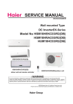
Wall mounted Type
DC InverterEK-Series
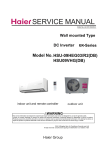
Model No. HSM18HEKC03/R2(DB)
HSM18HRAC03/R2(DB)
HUM18HC03/R2(DB)
HSM18HEKC03/R2(DB)
HSM18HRAC03/R2(DB)
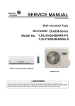
HUM18HC03/R2(DB)outdoor unit
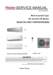
indoor unit and remote controller
2010
HSM18HEKC/HRAC03/R2(DB) HUM18HC03/R2(DB) -SM
Table of Contents
1. Introduction
1
2. List of Functions
6
3. Specifications
7
4. Printed Circuit Board Connector Wiring Diagram
9
5. Functions and Control
14
5.1 Main functions and control specifications of indoor unit
14
5.2 Main functions and control specifications of outdoor unit
22
5.3 Value of Thermistor
30
6. System Configuration
40
6.1 System Configuration
40
6.2 Instruction
40
7. Error Codes and Descirption
49
8. Installations
64
9. Removal Procedure
72
9.1 Removal of Indoor Unit(HSM18HEKC03/R2(DB)
72
9.2 Removal of Indoor Unit(HSM18HRAC03/R2(DB)
84
9.3 The removal procedure of outdoor
94
10. Wiring Diagrams
107
10.1 Indoor Unit ............................................................................................... 107
10.2 Outdoor Unit ............................................................................................ 108
11. Circuit Diagrams
109
12 .Description of Coding rules of Unit Model................................................112
HSM18HEKC/HRAC03/R2(DB) HUM18HC03/R2(DB) -SM
Introduction
1. Introduction
1.1 Safety Cautions
Be sure to read the following safety cautions before conducting repair work.
The caution items are classified into “Warning” and “Caution”. The “Warning” items are especially important
since they can lead to death or serious injury if they are not followed closely. The “Caution” items can also lead
to serious accidents under some conditions if they are not followed. Therefore, be sure to observe all the safety
caution items described below.
About the pictograms
This symbol indicates an item for which caution must be exercised.
The pictogram shows the item to which attention must be paid.
This symbol indicates a prohibited action.
The prohibited item or action is shown inside or near the symbol.
This symbol indicates an action that must be taken, or an instruction.
The instruction is shown inside or near the symbol.
After the repair work is complete, be sure to conduct a test operation to ensure that the equipment operates
normally, and explain the cautions for operating the product to the customer.
1.1.1 Caution in Repair
Warning
Be sure to disconnect the power cable plug from the plug socket before disassembling the equipment for
a repair.
Working on the equipment that is connected to a power supply can cause an electrical shook.
If it is necessary to supply power to the equipment to conduct the repair or inspecting the circuits, do not
touch any electrically charged sections of the equipment.
If the refrigerant gas discharges during the repair work, do not touch the discharging refrigerant gas.The
refrigerant gas can cause frostbite.
When disconnecting the suction or discharge pipe of the compressor at the welded section, release the
refrigerant gas completely at a well-ventilated place first.
If there is a gas remaining inside the compressor, the refrigerant gas or refrigerating machine oil
discharges when the pipe is disconnected, and it can cause injury.
If the refrigerant gas leaks during the repair work, ventilate the area. The refrigerant gas can generate
toxic gases when it contacts flames.
The step-up capacitor supplies high-voltage electricity to the electrical components of the outdoor unit.
Be sure to discharge the capacitor completely before conducting repair work.A charged capacitor can
cause an electrical shock.
Do not start or stop the air conditioner operation by plugging or unplugging the power cable plug.
Plugging or unplugging the power cable plug to operate the equipment can cause an electrical shock or
fire.
1
Domestic Air Conditioner
HSM18HEKC/HRAC03/R2(DB) HUM18HC03/R2(DB) -SM
Introduction
Warning
Do not repair the electrical components with wet hands. Working on the equipment with wet hands can
cause an electrical shock.
Do not clean the air conditioner by splashing water. Washing the unit with water can cause an electrical
shock.
Be sure to provide the grounding when repairing the equipment in a humid or wet place, to avoid electrical
shocks.
Be sure to turn off the power switch and unplug the power cable when cleaning the equipment. The
internal fan rotates at a high speed, and cause injury.
Do not tilt the unit when removing it. The water inside the unit can spill and wet the furniture and floor.
Be sure to check that the refrigerating cycle section has cooled down sufficiently before conducting repair
work. Working on the unit when the refrigerating cycle section is hot can cause burns.
Use the welder in a well-ventilated place. Using the welder in an enclosed room can cause oxygen
deficiency.
1.1.2 Cautions Regarding Products after Repair
Warning
Be sure to use parts listed in the service parts list of the applicable model and appropriate tools to
conduct repair work. Never attempt to modify the equipment. The use of inappropriate parts or tools can
cause an electrical shock, excessive heat generation or fire.
When relocating the equipment, make sure that the new installation site has sufficient strength to
withstand the weight of the equipment.
If the installation site does not have sufficient strength and if the installation work is not conducted
securely, the equipment can fall and cause injury.
Be sure to install the product correctly by using the provided standard installation frame.
For
Incorrect use of the installation frame and improper installation can cause the equipment to fall, resulting
in injury.
integral
units only
Be sure to install the product securely in the installation frame mounted on a window frame.
If the unit is not securely mounted, it can fall and cause injury.
For
integral
units only
2
Domestic Air Conditioner
HSM18HEKC/HRAC03/R2(DB) HUM18HC03/R2(DB) -SM
Introduction
Warning
Be sure to use an exclusive power circuit for the equipment, and follow the technical standards related to
the electrical equipment, the internal wiring regulations and the instruction manual for installation when
conducting electrical work.
Insufficient power circuit capacity and improper electrical work can cause an electrical shock or fire.
Be sure to use the specified cable to connect between the indoor and outdoor units. Make the
connections securely and route the cable properly so that there is no force pulling the cable at the
connection terminals.
Improper connections can cause excessive heat generation or fire.
When connecting the cable between the indoor and outdoor units, make sure that the terminal cover does
not lift off or dismount because of the cable.
If the cover is not mounted properly, the terminal connection section can cause an electrical shock,
excessive heat generation or fire.
Do not damage or modify the power cable.
Damaged or modified power cable can cause an electrical shock or fire. Placing heavy items on the
power cable, and heating or pulling the power cable can damage the cable.
Do not mix air or gas other than the specified refrigerant (R-410A / R22) in the refrigerant system.
If air enters the refrigerating system, an excessively high pressure results, causing equipment damage
and injury.
If the refrigerant gas leaks, be sure to locate the leak and repair it before charging the refrigerant. After
charging refrigerant, make sure that there is no refrigerant leak.
If the leak cannot be located and the repair work must be stopped, be sure to perform pump-down and
close the service valve, to prevent the refrigerant gas from leaking into the room. The refrigerant gas itself
is harmless, but it can generate toxic gases when it contacts flames, such as fan and other heaters,
stoves and ranges.
When replacing the coin battery in the remote controller, be sure to disposed of the old battery to prevent
children from swallowing it.
If a child swallows the coin battery, see a doctor immediately.
3
Domestic Air Conditioner
Introduction
HSM18HEKC/HRAC03/R2(DB) HUM18HC03/R2(DB) -SM
Caution
Installation of a leakage breaker is necessary in some cases depending on the conditions of the
installation site, to prevent electrical shocks.
Do not install the equipment in a place where there is a possibility of combustible gas leaks.
If a combustible gas leaks and remains around the unit, it can cause a fire.
Be sure to install the packing and seal on the installation frame properly. If the packing and seal are not
installed properly, water can enter the room and wet the furniture and floor.
For
integral
units only
1.1.3 Inspection after Repair
Warning
Check to make sure that the power cable plug is not dirty or loose, then insert the plug into a power outlet
all the way.
If the plug has dust or loose connection, it can cause an electrical shock or fire.
If the power cable and lead wires have scratches or deteriorated, be sure to replace them.
Damaged cable and wires can cause an electrical shock, excessive heat generation or fire.
Warning
Do not use a joined power cable or extension cable, or share the same power outlet with other electrical
appliances, since it can cause an electrical shock, excessive heat generation or fire.
4
Domestic Air Conditioner
HSM18HEKC/HRAC03/R2(DB) HUM18HC03/R2(DB) -SM
Introduction
Caution
Check to see if the parts and wires are mounted and connected properly, and if the connections at the
soldered or crimped terminals are secure. Improper installation and connections can cause excessive
heat generation, fire or an electrical shock.
If the installation platform or frame has corroded, replace it. Corroded installation platform or frame can
cause the unit to fall, resulting in injury.
Check the grounding, and repair it if the equipment is not properly grounded. Improper grounding can
cause an electrical shock.
Be sure to measure the insulation resistance after the repair, and make sure that the resistance is 1 M
ohm or higher.
Faulty insulation can cause an electrical shock.
Be sure to check the drainage of the indoor unit after the repair.
Faulty drainage can cause the water to enter the room and wet the furniture and floor.
5
Domestic Air Conditioner
HSM18HEKC/HRAC03/R2(DB) HUM18HC03/R2(DB) -SM
Functions
Category
Healthy negative ion make your room full of an abundance natural negative ions.
HSM18HEK/HRACC03/R2(DB)
HUM18HC03/R2(DB)
N
Child lock
Avoid the child's wrong operation on the remote controller
Y
3D air flow
The 3D airflow is able to deliver the airflow horizontally and vertically.
N
24Hour timer
Use the timer function to set on,or off,or from on to off,or from off to on
Y
Easy clean design The panel is easy to wash and the airflow vents can be detached easily
Y
With twin-blade technology ,the airflow can be adjusted not to blow directly
Y
Catches most small particles and remove unpleasant odors effectively.
Y
Sleep mode
The setting temprature and the indoor noise can be adjusted to a more comfortable
level when you set the "sleep mode"during night sleep
Y
4 Fan setting
Slect the fan speed LO,MED,HI,AUTO
Y
adjust the last fixed operation mode automatically.
Y
Quick cooling or heating
Y
lower noise operation condition
Y
Intelligent air
Anti-mold filter
Auto mode
Power mode
Soft mode
Constant temperature
Make dehumidifying in the room while keeping the constant temperature inside
dehumidification
Note: Y: Holding Functions
N : No Functions
N
HSM18HEKC/HRAC03/R2(DB) HUM18HC03/R2(DB) -SM
HSM18HEKC03/R2(DB)
1.5~4.9~5.5
1.6~5.35~5.8
HSM18HRAC03/R2(DB)
1.5~4.9~5.5
1.6~5.35~5.8
5100~16700~18700 5400~18200~19800 5100~16700~18700 5400~18200~19800
1290~4214~4730
1376~4601~4988
1290~4214~4730
1376~4601~4988
2.0
2.0
6.9
6.6
400~1530~1950
405~1480~2000
6.9
6.6
400~1530~1950
405~1480~2000
96
97
96
97
3.20
3.61
3.20
3.61
6.35
6.35
12.7
12.7
16.0
16.0
25
25
15
15
7
10
20
20
14.2
15.0
14.2
15.0
12.7
13.5
12.7
13.5
11.2
13.0
11.2
13.0
-
-
-
-
4
4
0.15
0.15
0.15
0.15
33
33
33
33
938X187X265
938X187X265
1016X304X360
1016X304X360
10.5
10.5
12.5
12.5
42/39/36
42/39/36
52
52
HSM18HEKC/HRAC03/R2(DB) HUM18HC03/R2(DB) -SM
HUM18HC03/R2(DB)
SNB130FGYM2
900
FV50S
0.5
R410a
1.2
35
35
1235.5
1235.5
40
6.9
6.6
1530
1480
98
98
15
820X310X682
919X106X715
43
46.5
51
61
5
8
HSM18HEKC/HRAC03/R2(DB) HUM18HC03/R2(DB) -SM
Connector Wring Diagram
4.Printed Circuit Board Connector Wiring Diagram
4.1˖Indoor unit Connectors
Connectors
PCB(1) (Control PCB) For HUM18HC03/R2(DB)
1) CN26 Connector for fan motor
2) CN1 Connector for heat exchanger thermistor and Room temperature thermistor
3) CN11 Connector for UP&DOWN STEP motor
4) CON2 Connector for power N wire
5) CON1 Connector for power L
6) CN32 Connector for display board
7) C0N6,C0N8 Connector for ions generator
8) CON7 Connector for communicate between the indoor board and the outdoor
board
9) CON9 Connector for new airflow wire
10) CN34 Connector for long-range control
11) CN20 Connector for room card
Note: Other designations
PCB(1) (INdoor Control PCB)
1) SW1 Connector for Forced operation ON / OFF switch
2) SW2 1 Select remote code A or B,2 Select 25 or 35 ,3 Select room card able or
disable
3) SW4 Select 20 or other,if select 20,SW2 must select 25(Select ON)
4) RV1 Varistor
5) FUSE1 Fuse 3.15A/250VAC
9
Domestic Air Conditioner
HSM18HEKC/HRAC03/R2(DB) HUM18HC03/R2(DB) -SM
Connector Wring Diagram
PCB(1)
CN26
CN1
SW1
CN11
CN32
CN20
CON6
CON1
CON9
CON2
CON6
CON7
CN34
10
Domestic Air Conditioner
HSM18HEKC/HRAC03/R2(DB) HUM18HC03/R2(DB) -SM
Connector Wring Diagram
4.2: outdoor unit
Connectors
PCB(1) (Control PCB)
1) CN1,CN2 Connector for power N and L
2) CN3 Connector for ground
3) CN6 CN7 Connector for terminal to indoor unit
4) CN25 Connector for DC POWER 15Vand 5V to the module board
5) CN9,CN10 Connector for CN2,CN1 on the module board
6) CN12 Connector for AC fan motor
7) CN11 Connector for four way valve coil
8) CN17,CN18,CN19, CN47 Connector for thermistors
9) CN24 Connector for communicate between the control board and the module board
10) CN25 CN28 Connector to P and N of the module board
11) CN36 Connector for communicate between indoor and outdoor unit
12) CN15 Connector for electric expansion valves
13) CN45 Connector for terminal socket protect
14) CN22 Connector for DC fan motor
PCB(2) (module PCB)
CN10 Connector for the DC power 5V and 15V form the control PCB
CN11 Connector for communicate between the control board and the module board
P( CN8), N(CN9) Connector for capacitance board
LI (CN3),LO(CN4) Connector for reactor
CN5ˈCN6ˈCN7 Connector for the U, V, W wire of the compressor
Note: Other Designations
PCB(1) (Control PCB)
1) FUSE 1, (25A,250VAC) FUSE 2(1A,250VAC)
2)LED 1 keep light representative normal ,if keep flash interval representative trouble Alarm
3)RV1,RV2,RV3 Varistor
11
Domestic Air Conditioner
HSM18HEKC/HRAC03/R2(DB) HUM18HC03/R2(DB) -SM
Connector Wring Diagram
PCB(1)
CN28 CN25
CN22 CN23
CN22
CN21
CN20
CN19
CN18
CN17
CN47
CN16
CN15
CN45
CN12
CN1
CN2
CN11
CN36
CN10
CN8
CN4
CN7
CN6
12
Domestic Air Conditioner
HSM18HEKC/HRAC03/R2(DB) HUM18HC03/R2(DB) -SM
Connector Wring Diagram
PCB(2)
CN4
CN2
CN1
CN3
CN10
CN9
CN8
CN7
CN5
CN6
CN11
13
Domestic Air Conditioner
Function and control
HSM18HEKC/HRAC03/R2(DB)HUM18HC03/R2(DB)-SM
5.Funcitions and Control
5.1 Main functions and control specification of indoor unit
5.1.1 Automatic operation
When the running mode is turned to automation after starting the system, the system will first
determine the running mode according to the current room temperature and then will run according to
the determined mode. Tr in the following selection conditions means room temperature, Ts means
setting temperature, Tp means temperature of indoor coil pipe
Tr≥23ć
Choose Cooling Mode
Tr˘23ć
Choose Heating Mode
After turning to the automation mode, the running mode can be switched between cooling mode, fan
mode and heating mode according to the change of the indoor ambient temperature. But the
automatic conversion between cooling mode and heating mode must be conducted after 15 minutes.
5.1.2
Cooling operation mode
Temperature control range: 16ć---30ć
Temperature difference: ±1ć
* Control features: When Tr˄input airflow˅>Ts˄set temperature˅ć, the compressor will be opened,the
indoor fan will operate at the set speed and the mode signal will be sent to the outdoor system. When
Tr˄input airflow˅< Ts˄set temperature˅ć, the compressor will be opened,the indoor fan will operate
at the set speed and the mode signal will be sent to the outdoor system. The system will keep the
original status if Tr= Ts.
Airflow speed control: (temperature difference 1ć)
Automatic: When Tr>=Ts+3ć, high speed.
When Ts+1ć=<Tr<Ts+3ć, medium speed
When Tr<Ts+1ć, low speed
When the sensor is off, low speed
When the airflow speed has no delay from the high to low switching, the speed should be delayed for
3 minutes (remain at high speed for 3 minutes.) before the next switch.
Manus: When the system is operating, you can set the high, medium or low speed manually. ( When
the sensor is on or off, the system will change the speed 2 seconds after receiving the signal.)
*Airgate location control: the location for the airgate can be set according to your needs.
*Defrosting function: preventing the frosting on the indoor heat exchanger (when cooling or
demoisture). When the compressor works continuously for 1/6 minutes (adaptable in EEPROM) and
the temperature of the indoor coils has been below zero centigrade for 10 seconds, the compressor
will be stopped and the malfunction will be recorded in the malfunction list. The indoor system will
continue to run. When the temperature of the indoor coil is raised to 7ć, the compressor will be
restarted again (the prerequirement of 3 minutes’ delay should be satisfied.)
* timing system on/off function.
* Dormant control function.
14
Domestic Air Conditioner
HSM18HEKC/HRAC03/R2(DB)HUM18HC03/R2(DB)-SM
5.1.3
Function and control
Demoisture mode.
* temperature control range:
16---30ć
* temperature difference: ±1ć
Control feature: send the demoisture signal to the outdoor system.
When Tr>Ts+2ć, the compressor will be turned on, the indoor fan will operate at the set speed.
When Tr is between the Ts and Ts+2ć, the outdoor system will operate at the high demoisture
frequency for 10 minutes and then at the low demoisture mode for six minutes. The indoor fan
will operate at low speed.
When Tr< Ts, the outsystem will be stopped, the indoor fan will be stopped for 3 minutes and
then turned to the low speed option.
All the frequency converses have a ±1ć difference.
* Wind speed control: Automatic:
When Tr >= Ts+ 5ć, high speed.
When Ts+3ć≤Tr< Ts+5ć, medium speed.
When Ts+2ć≤Tr< Ts+3ć, low speed.
When Tr<Ts+2ć, light speed.
If the outdoor fan stopped, the indoor fan will be paused for 3 minutes.
If the outdoor fan stopped for more than 3 minutes and the outdoor system still operates, the
system will be changed into light speed mode.
When the airflow speed has no delay from the high to low switching, the speed should be
delayed for 3 minutes (remain at high speed for 3 minutes.) before the next switch.
Manual: When the sensor is off or Tr< Ts+3ć, the manual operation can not be made. (obligatory
automatic operation.)
*Airgate location control: the location for the airgate can be set according to your needs.
*Defrosting function: preventing the frosting on the indoor heat exchanger (when cooling or
demoisture). When the compressor works continuously for 1/6 minutes (adaptable in EEPROM)
and the temperature of the indoor coils has been below zero centigrade for 10 seconds, the
compressor will be stopped and the malfunction will be recorded in the malfunction list. The
indoor system will continue to run. When the temperature of the indoor coil is raised to 7ć, the
compressor will be restarted again (the prerequirement of 3 minutes’ delay should be satisfied.)
* coil protection (synchronic overheating protection) are installed for the four directions latch
malfunctions when demoisturing.
* timing system on/off function.
* Dormant control function.
5.1.4
Heating operation mode.
* temperature control range: 16---30ć
* temperature difference:
±1ć
* control feature: the temperature compensation is automatically added and the system will send the
heating signals to the outdoor system.
If Tr≤Ts, the outdoor compressor is turned on, the indoor fan will be at the cold air proof mode.
If Tr>Ts+3, the outdoor system is turned off, the indoor fan will be at the heat residue sending mode.
If Tr<Ts+3ˈthe outdoor system will be turned on again, the indoor fan will be at the cold air proof
mode.
15
Domestic Air Conditioner
Function and control
HSM18HEKC/HRAC03/R2(DB)HUM18HC03/R2(DB)-SM
*Indoor fan control
manual control: You can choose high, medium, low and automatic speed control.
Automatic: When Tr<Ts, high speed.
When Ts=<Tr=<Ts+2ć, medium speed.
When Tr> Ts+2ć, low speed.
When the airflow speed has no delay from the high to low switching, the speed should be delayed for
3 minutes (remain at high speed for 3 minutes.) before the next switch.
*Airgate location control: the location for the airgate can be set according to your needs.
Coldair proof operation
1. The indoor operation within 4 minutes after the start up is as the following diagram, the air speed
can be raised only after the speed has reached a certain level.
Set speed
Heat start temp 1
Low speed
Keep
the
high speed.
The
fan
doesn’t stop
Heat start temp 2
Light speed
Heat start temp 3
Fan/off
Heat start temp 4
Fan/off
2. 4 minutes after the start up of the indoor fan, the light airflow and the low airflow will be turned to the
set speed airflow.
3. In the cold air proof operation, the fan won’t stop after the start up.
4. During the cold air proof operation, the indoor system will continuously send ‘indoor high speed’
signals to the outdoor system.
* Residue heat sending. The indoor fan will send the residue heat at a low speed for 20 seconds.
If other conditions are satisified, when the compressor stops, the indoor system will operate at a light
speed. The indoor fan will stop when the coil temperature is below the ‘heat start temp 4’.
* Defrosting. When the system receives the defrosting signal from outdoors, the indoor fan will stop
and the indoor temperature display won’t change. At the time, any indoor coil malfunctions will be
neglected. When the outdoor defrosting finishes, the coil malfunction will still be neglected until the
compressor has been started up for 30 seconds. The indoor temperature display will not change and
the system operates at the cold air proof mode.
* Automatic heating temperature compensation: when the system enters the heating mode, the
temperature compensation (4) will be added. When the status is switched off, the compensation will
be erased.
5.1.5
strength operation
a. the system enters the mode after receiving the ‘strength signal’.
Send strength operation signal to the outdoor system.
Strength operation quit if you change the fan mode or operation mode .
The mode change finishes the strength operation.
Entering ‘mute’, you can have normal operation or signal control such as timing to finish the strength
16
Domestic Air Conditioner
Function and control
HSM18HEKC/HRAC03/R2(DB)HUM18HC03/R2(DB)-SM
operation.
When the system is at the automatic option ,There is no strength/ mute function,.
5.1.6
Mute operation
the system enters the mode after receiving the ‘mute signal’.
a. Mute heating: the airflow speed is slight, the system sends the mute signal to the outdoor system.
b. mute cooling: the airflow speed is slight, the system sends the mute signal to the outdoor system.
When the compressor operates, the airflow speed is mute speed. EEPROM is adaptable.
Mute operation can not work under the demoisturing and airflow-sending operation.
5.1.7
Air refreshing
After receiving the signal from the remote control,(HV series: the background light of the ‘health’ logo
is green. HS series: the ‘health’indicator will be lighted). If the fan operates, the negative ion generator
operates to realize the negative sending function.
If the indoor fan stops, the negative ion generator is turned off.
When the negative ion generator is turned off, if the air refreshing system is turned on, the negative
ion generator will be turned on when the fan operates.
5.1.8
Timing.
You can set 24 hours’ on/off timing accordingly. After the setting, the timing indicator will be lightened.
Also, the light will be turning off after the timing is finished. The followings are several timing methods.
1.system /on timing: The timing indicator will be lightened and the indoor system is under the waiting
mode. The light will be turned off when the timing is finished and the rest of the system will operate
under a normal condition. The timing starts since the last reception of the timing singal. You can have
the dormacy setting under the timing mode, the order of your settings will be operated according to
the timing settings.
2.system /off timing: When the system is turned on, the timing indicator is lightened, the rest of the
system will operated under a normal condition. When set time comes, the indicator light will be turned
off and the system will be turned off. If you have set the dormant functions, the order of your settings
will be operated according to the timing settings.
3.system /on and off timing: The settings will be completed according to the orders.
5.1.9
Dormant operation
The dormant timing is an eight hours unadaptable one. The timing signs are shown on the E series
board. (RC series show the dormant signal, the timing light is lighted on the 6 lights board).
2.1 Under the cooling/ demoisture operation, after the setting of the dormant operation, the set
temperature will be raised for 1 centigrade after 1 hour’s operation and will be raised for 1 centigrade
1 hour later. The system will keep this status for 6 hours and then close.
2.2 Under the heating mode, after the setting of the dormant operation, the et temperature will fall 2
17
Domestic Air Conditioner
HSM18HEKC/HRAC03/R2(DB)HUM18HC03/R2(DB)-SM
Function and control
centigrades after 1 hour’s operation and will fall 2 centigrades 1 hours later. 3 hours after the
preceding operations, the set temperature will be raised for 1 centigrade and the system will keep this
status for 3 hours and then close down.
2.3 During the dormant time, except the change of the system mode or a new press on the dormant
setting keys, the timing of the 8 hours dormancy will take the first timing as the start time, any presses
on other keys will not affect the original timing.
2.4 Indoor fan control under the dormant operation.
If the indoor fan is at the high speed before the dormant operation setting, the speed will be turned to
medium after the setting. If the fan is at the medium speed before the dormant setting, the speed will
be turned to low after the setting. If the fan is at the low speed before the dormant setting, the speed
will not change.
5.1.10 Urgent on/off input
Press the urgency button the buzzer will ring. The system will enter the automatic mode if you don’t
press the button for more than 5 seconds.
Under the system off mode, if you press the urgency key for 5 to 10 seconds, the system will start the
test operation.
Under the system off mode, If you press the urgency key for 10 to 15 seconds, the display screen will
show the resume of the last malfunction.
If the system is under operation, the press on the urgency key will stop it.
Under the system off mode, the display screen will show no sign.
Urgency operation: If you press the urgency key for less than 5 seconds, the buzzer will ring when you
press the on/off key. The system will enter the urgency operation when the urgency key is loosened.
The urgency operation is fully automatic.
Test operation.
The inlet temperature sensor doesn’t work, the indoor fan and the indoor air direction board motor
works synchronically. High speed airflow, cooling, outdoor system on, etc, will send the ambient
temperature 30 centigrade and coil temperature 16 centigrade information to the outdoor system.
Test operation
The defrost protection of the evaporator doesn’t work.
The temperature control doesn’t work.
The test operation will be finished in 30 minutes.
The test operation can be stopped by the relative commands from the remote control.
5.1.11 Low load protection control
In order to prevent the frosting of the indoor heat interaction device, the outdoor system will be
stopped if the indoor heat interaction temperature is below zero centigrade for 5 minutes, but the fan
will continue to operate. The outdoor system will be started again when the heat interaction
temperature is above 7 centigrade and the system has been stopped for 3 minutes. The malfunction
will be stored in the malfunction resume and will not be revealed.
18
Domestic Air Conditioner
Function and control
HSM18HEKC/HRAC03/R2(DB)HUM18HC03/R2(DB)-SM
5.1.12 High load protection control
The outdoor system will be stopped if the coil temperature is above 65ć for 2 minutes. The indoor fan
will be controlled by the thermostat. The outdoor system can be restarted when the coil temperature is
below 42ć and the system has been stopped for 3 minutes. The malfunction will be stored in the
malfunction resume and will not be revealed.
5.1.13 Abnormal operation of indoor system
When the outdoor system operates, if the indoor system operation differs from the outdoor system,
the abnormal operation malfunction will be reported. 10s after the report, the indoor system will be
closed.
Outdoor system mode
Indoor system mode
conflicts
cooling
heating
yes
cooling
cooling
no
cooling
airflow
no
heating
heating
no
heating
airflow
yes
heating
cooling
yes
5.1.14 Malfunction list resume.
Nothing is presented if there is no code list.
The malfunction display will automatically finish in 10 seconds.
The remote control only receives the sigals for stop. According to the signals, the malfunction resume
presentation finishes.
The resume restores after the power supply restores.
5.1.15 Abnormality confirmation approaches.
1.indoor temperature sensor abnormality:
under the operation, the normal temperature ranges from 120 degree to -30 degree. When the
temperature goes beyond this range, the abnormality can be confirmed. If the temperature goes back
into the range, the system will automatically resume.
2.indoor heat interaction sensor abnormality:
under the operation, the normal temperature ranges from 120 degree to -30 degree. When the
temperature goes beyond this range, the abnormality can be confirmed. If the temperature goes back
into the range, the system will automatically resume.
3.indoor malfunction:
Out door malfunction: When the indoor system receives the outdoor malfunction codes, it will store
the code into E2 for the malfunction list resume. The indoor system will continue to operate according
to the original status, the malfunction code will not be revealed or processed.
4.transmission abnormality:
If the indoor system can’t receive the outdoor system for 8 minutes, the communication abnormality
19
Domestic Air Conditioner
Function and control
HSM18HEKC/HRAC03/R2(DB)HUM18HC03/R2(DB)-SM
can be confirmed and reported and the outdoor system will be stopped.
5.1.16 Single indoor system operation
* Enter condition: First, Heating operation mode, set the high speed airflow and 30 centigrade set
temperature, then press the dormant keys for 6 times within 7 seconds, the system will feedback with
6 rings.
* After the system enters the separate indoor system operation mode, the indoor system will operate
according to the set mode and neglect the communication signals of the outdoor system. However, it
has to send signals to the outdoor system.
* Quitting condition: This mode can be quitted after receiving the quitting signal from the remote
control or urgency system. The indoor system thus can quit the single operation mode.
5.1.17 Power cut compensation.
* Entering condition: Press dormant button 10 times within 7 second, the buzzer will ring 4 times and
the present system status will be stored into the EEPROM of the indoor system.
* After entering the power cut compensation mode, the processing of the indoor system should be as
the followings:
Remote control urgency singal: operate according to the remote control and the urgent conditions,
the present status will be stored into the EEPROM of the indoor system.
* Quitting conditions: Press dormant button 10 times within 7 seconds and the buzzer will ring twice.
5.1.18 Fixed frequency operation.
1. Fixed cooling: a. under G code condition: high speed cooling, set 16ć, press temperature ‘-‘ key
and the set key at the same time. The system will enter the fixed frequency operation after the buzzer
rings twice.
b. The proceeding programs are as the follows:
Entering the fixed frequency operation, you can set the fixed strength location 1 and send the coolng
signal to the outdoor system. Meanwhile, you can fix the indoor system at high speed mode, the
location of the airflow directin board can be switched to the maximal position.
c. Quitting condition: The fixed frequency cooling can be quitted after receiving the remote signal, and
the system will enter the remote setting status.
2. Fixed heating: a. under G code condition: high speed heating, set 30ć, press temperature ‘+‘ key
and the set key at the same time. The system will enter the fixed frequency operation after the buzzer
rings twice.
b. The proceeding programs are as the follows:
Entering the fixed frequency operation, you can set the fixed strength location 1 and send the heating
signal to the outdoor system. Meanwhile, you can fix the indoor system at high speed mode, the
location of the airflow directin board can be switched to the maximal position.
c. Quitting condition: The fixed frequency heating can be quitted after receiving the remote signal, and
the system will enter the remote setting status.
20
Domestic Air Conditioner
Function and control
HSM18HEKC/HRAC03/R2(DB)HUM18HC03/R2(DB)-SM
5.1.19 Time cutting function:
connect the test program terminal on the mainboard after connecting the system to the power circuit.
The CPU of the main control will be 60 times faster.
5.1.20 Display function
When the system starts up or power on, the background and the LED will be fully lighted for 3
seconds. Then the LED displays the mode you have set.
5.1.20.1 Three-color background
The multi-color indicator is not lighted when the system is off. The mode-switching will change the
indicator colors. Red color is for heating mode, blue for cooling, water color for demoisturing, white for
automatic mode, pink for airflow sending, green for health mode and yellow green for air refreshing.
The colors health, refreshing colors are preferred to the mode colors. If different status exist at the
same time, then the last set color will be shown. The lighting key of the control board can turn on or off
the display.
5.1.20.2 LED display
*Set timing to display timing signs, set dormant mode to display dormant sign.(The dormant signs will
be shown on the G series panels.), set health mode to display health sign, set new airflow mode to
display new airflow sign and set violet disinfection to display health sign.
*Set auto, heating, demoisturing, heating to display the relative signs. When you use a remote control
to switch cooling, demoisturing and heating modes, the set temperature will be shown and the screen
board will return to the room temperature 5 seconds later. If you choose the airflow sending mode, the
screen board will show the room temperature directly.
*If the system is under malfunction status, the display will show the malfunction code. Please refer to
the malfunction list.
5.2 The control system of outdoor unit
5.2.1˖The operation frequency of outdoor unit and its control
5.2.1.1˖The operation frequency control of compressor
The operation frequency scope of compressor˖
Mode
Minimun operation frequency
Maximun operation frequency
Heating
20Hz
100Hz
Refrigeration
20 Hz
9 0 Hz
5.2.1.2˖The starting of compressor
When the compressor is started for the first time, it must be kept under the conditions of 58Hz,88Hz
for one minute (the overheating protection of the outdoor unit air-blowing temperature, immediately
decrease the frequency when the compressor is overflowing and releasing the pressure)ˈthen it can
be operated towards the target frequency. When the machine runs normally, there’s no such process.
After starting the compressor for operation, the compressor should run according to the calculated
frequency, and every determined frequency for protection should be prior to the calculated frequency.
5.2.1.3˖The speeds of increasing or decreasing the frequency of the compressor
21
Domestic Air Conditioner
Function and control
HSM18HEKC/HRAC03/R2(DB)HUM18HC03/R2(DB)-SM
The speed of increasing or decreasing the frequency rapidly 1 -----------1HZ/second
The speed of increasing or decreasing the frequency slowly 2 -----------1HZ/10seconds
5.2.1.4˖The calculation of the compressor’s frequency
1˅ǃThe minimum/maximum frequency limitation
AˊWhile refrigerating: ˢˉ˩˝˴ˉ̎ is the maximum operation frequency of the compressor;
ˢˉ˩INˉ̎ is the minimum operation frequency of the compressor.
BˊWhile heating: ˢˉ˩˝˴ˉ̀ is the maximum operation frequency of the compressor; ˢˉ
˩INˉ̀is the minimum operation frequency of the compressor.
1˅ǃThe frequency limitation which is affected by the environment temperature.
Heating mode:
Serial No.
Temperature scope
Frequency limitation
1
Wh_c<-12
Max_hz8 100 HZ
2
Wh_c<-8
Max_hz7 100HZ
3
Wh_c<-2
Max_h z4 100HZ
4
Wh_c<5
Max_hz5
90 HZ
5
Wh_c<10
Max_hz1
80 HZ
6
Wh_c<17
Max_hz2
70 HZ
7
Wh_c<20
Max_hz6
60HZ
8
Wh_c>˙20
Max_hz3
48HZ
Remarks: the above are the maximum frequency limitations of the complete appliance which are
affected by the environment, and they have nothing to do with the ability of the indoor unit.
Refrigeration/dehumidification mode:
Serial No.
Temperature scope
Frequency limitation
1
Wh_c<28
Max_hz1 45HZ
2
Wh_c<32
Max_hz2 70 HZ
3
Wh_c<40
Max_hz3 90 HZ
4
Wh_c<48
Max_hz4 70 HZ
5
Wh_c>˙48
Max_hz5 48 HZ
Remarks: the above are not only the maximum frequency limitations of the complete appliance which
are affected by the environment, but also the maximum ability limitation of the system. When the
starting ability is not the maximum, its maximum frequency limitation is calculated by the following
equations:
The frequency limitation which is affected by the temperature and under the condition of actual ability
˙the actural running system ability*the maximum frequency which is limited by the temperature and
under the condition of maximum ability/the maximum designing ability of the system
ΔT=∑˄ΔTi*Pi˅/∑Pi (ΔTi=|Tst_i-Tnh_i the indoor environment temperature| ;Pi˙i the ability of the
indoor unit)
Refrigeration/dehumidification:
<1
˙1
˙2
˙3
>=4
50%
70%
100%
120%
140%
ΔT
<1
˙1
˙2
˙3
>=4
The percentage of the
50%
70%
100%
140%
140%
ΔT
The percentage of the
rated frequency P
Heating mode˖
rated frequency P
22
Domestic Air Conditioner
HSM18HEKC/HRAC03/R2(DB)HUM18HC03/R2(DB)-SM
Function and control
K=∑Ki/the number of running machines
The indoor set
Breeze
Low
Medium
High
Strong
Quiet
airflow speed
The percentage
of
the
Healthy
airflow
70ˁ
70%
90%
100%
120%
70%
70%
rated
frequency Ki
The calculation of the actual output frequency: when there is no healthy airflow: F =F-ED-*×P×K
When the healthy airflow has been set: F =F-ED-*×P×K˄airflow speed˅×K˄healthy airflow˅
When refrigerating, it is needed to satisfy ˢˉ˩INˉ̀< F<ˢˉ˩˝˴ˉ̀
When heating, it is needed to satisfy ˢˉ˩INˉr< F<ˢˉ˩˝˴ˉr
5.2.2: The outdoor fan control (exchange fan)
When the fan is changed among every airflow speed (including stop blowing), in order to avoid the
airflow speed from skipping frequently, it must be kept under each mode for over 30 seconds, and
then it can be changed to another mode (when refrigerating, the time is changed to 15 seconds).
5.2.2.1:The outdoor fan control when refrigerating or dehumidifying
After the compressor is started for 5 seconds, the outdoor fan is started at the medium speed at first,
after 30 seconds,it begins to control the airflow speed according to the temperature conditions of the
outdoor environment.
The temperature of the
The temperature of the outdoor
outdoor air ˄Ta˅
coil˄Te˅
Airflow speed
Ta? 30?
——
High
26?? Ta<30
?
——
K e e p in g t h e s p e e d
24?? Ta<26
?
——
M e di u m
23?? Ta<24
?
——
K e e p in g t h e s p e e d
5?? Ta<23
?
——
Low
Ta<5?
15?? Te
Low
15? >Te
Stop
5.2.2.2:The outdoor fan control when heating
The temperature of the outdoor
Airflow speed
air ˄Ta˅
Ta? 22?
Low
19?? Ta<22
?
Ke e p i ng t h e s p e e d
16?? Ta<22
?
Me diu m
14?? Ta<16
?
Ke e p i ng t h e s p e e d
Ta<14?
High
23
Domestic Air Conditioner
Function and control
HSM18HEKC/HRAC03/R2(DB)HUM18HC03/R2(DB)-SM
5.2.3˖The control of the outdoor electronic expansion valve
When starting the compressor: the opening size of the valve must be guaranteed to have entered into
the standard opening size, and then the compressor can be started.
When refrigeration is in vain (the machine is shut down or is in the state of retrograde operation), the
opening size of the expansion valve of the indoor unit is 5 steps;
When heating is in vain, the opening size of the expansion valve of the indoor unit is 55 steps;
When the outdoor unit is shut down, the valve is opened completely for 2 minutes, and then begin
initialization.
The scope of refrigerationg valve
60-----480 steps
The scope of heating valve
90-----480 steps
The valves are adjusted according to the degree of superheat —SHaˈƸSHa.
5.2.4˖Four way control
For the details of defrosting four-way valve control, see the defrosting process.
Four way working in other ways:
Under the mode of heating, open the four-way valve, when the compressor is not started or changed
to non-heating mode, make sure the compressor is stoped for 2 minutes, and then close the four-way
valve.
5.2.5˖The outdoor defrosting control
A.The conditions for entering into defrosting mode
When starting running heating, the compressor continuously runs for over 10 minutes, after running
for 45 minutes in all (defrosting is ended or when entering into refrigeration mode, clear the
compressor’s cumulative run time), through detecting the defrosting sensor TCS˄detect the defrosting
situation of the heat exchanger of the outdoor unit˅and the outdoor environment temperature sensor
TA, and meeting the following conditions continuously for 2 minutes, the machine enters into the
defrosting operation:
TCS≤C×TAˉα
α is determined as the following according to the data of EEPROM:
C selcet˖if Tao˘0ćˈC=0.8;if Tao≥0ćˈC=0.6 ˈαis read from EEPROMˈNormal State: α=6
The temperature limitation for entering into defrosting mode -15ć≤C×TAˉα≤-5ć
B.Defrosting time interval
When the result of C×TAˉα is in the scope of -15ć≤C×TAˉα, the interval between two defrostings is
45 minutes (the time interval which is in 57 digits in EEPROM can be adjusted˅
When the result of C×TAˉα is in the scope of C×TAˉα<-15ć, the time interval between two
defrostings is 65 minutes.
C.Defrosting operation
When starting defrosting, the compressor stops for 1 minute at first, and the outdoor fan is running,
after 55 seconds, the four-way valve is off.
When the compressor is started, the outdoor fan is stoped, the compressor stops for 30 seconds at
the conditions of 58HZ, and then runs towards the target frequency—88HZ.
During defrosting period, the protections, such as current of the compressor, compressor’s blowing
24
Domestic Air Conditioner
HSM18HEKC/HRAC03/R2(DB)HUM18HC03/R2(DB)-SM
Function and control
and so on, are in effect. During defrosting period, the compressor which is stoped because of
protection or malfunction will reinstate after stoping for 3 minutes, and don’t clear the cumulated run
time. When it is satisfied with the continuously running time, it will enter into the defrosting mode.
After entering into defrosting mode, make sure the compressor runs for at least for 2 minutes, and
then it can withdraw from defrosting.
If a single machine causes defrosting, the other machines all involve in defrosting.
D.The conditions of withdrawing from defrosting
The defrosting operation will change to heating operation, if any of the following conditions is satisfied:
˄1˅
˖The temperature of the outdoor heat exchanger is continuously over 7ć for 80 seconds.
˄2˅
˖The temperature of the outdoor heat exchanger is continuously over 12ć for 5 seconds.
˄3˅
˖Continuously run defrosting for 11 minutes˄56 digits in EEPROM can be adjusted˅.
EˊWhen satisfying the conditions of withdrawing from defrosting, the machine works as the
followings:
The compressor stops, the outdoor fan is started, and the four-way valve is closed, after 60 seconds
the compressor runs according to the starting process.
5.2.6 Protection function
5.2.6.1˖TTC high temperature-preventing protection
Once the machine is started, it can run TTC overheating protection of air-blowing, but air-blowing
sensor malfunction must alarm after 4 minutes during which the compressor is started (during the
course of self-detection, there’s no such limitation)
Sensor detection methods: 100 times (one cycle of procedure run is one time, and about 5ms,
detection method for each time: continuously sampling for 8 times, then order them and take the
mean value of the middle 2 values), take the mean value.
TTC˄ć˅
117
Abnormal stop
Decreasing the frequency rapidly˄1HZ/second˅
112
Decreasing the frequency slowly (1HZ/10seconds)
108
105
The frequency doesn’t change.
Increasing the frequency (1HZ/10second)
98
Increasing the frequency˄1HZ/1second˅
TTC>=110ć lasts for 20 seconds. Overheating protection of air-blowing, alarm malfunction to the
indoor, others don’t last.
5.2.6.2˖TC high temperature-preventing control of the indoor heating unit˖
Tpg_indoor is the highest value of the effective indoor unit (start it and it is in accord with the running
25
Domestic Air Conditioner
Function and control
HSM18HEKC/HRAC03/R2(DB)HUM18HC03/R2(DB)-SM
state).
The indoor heat exchanger sensor tests the temperature of the indoor heat exchanger. If the
temperature is higher than 55ć, decrease the rotate speed of the compressor and do the high
temperature-preventing protection of the indoor heat exchanger; if the temperature of the indoor heat
exchanger is lower than 47ć, recover to the normal control.
TC
Fgh_t1ˉ2
Fgh_t2ˉ2
N
P
Fgh_t3ˉ2
Q
Fgh_t4—2
Fgh_t5—2
Normal
R
The compressor stops
Fgh_t1 65ć
Decreasing the frequency rapidly Fgh_t2 63ć
Decreasing the frequency slowly
Fgh_t3
55ć
Prohibiting increasing the frequency
Fgh_t4
52ć
Increasing slowly
Fgh_t5
48ć
N˖Decreasing at the speed of 1HZ/1 second
P˖Decreasing at the speed of 1Hz/10 seconds
Q˖Continue to keep the last-time instruction cycle
R˖Increasing at the speed of 1Hz/10seconds
Remarks: the outdoor unit
5.2.6.3 The control of preventing the overcurrent of the compressor˖
●During the starting process of the compressor, if the curren of the compressor is greater than 12A for
3 seconds, stop the compressor and alarm, after 3 minutes, start it again, if such state appears 3
times in 20 minutes, stop the compressor and alarm, and confirm the malfunction. Then continue to
run it only after the the power is off.
●During the starting process of the compressor, if the AC current is greater than 11A, the frequency of
the compressor decreases at the speed of 1HZ/second.
●During the starting process of the compressor, if the AC current is greater than 10A, the frequency of
the compressor decreases at the speed of 0.1HZ/second.
●During the starting process of the compressor, if the AC current is greater than 9.5A, the frequency
of the compressor increases at the prohibited speed.
●During the starting process of the compressor, if the AC current is greater than 9A, the frequency of
the compressor increases at the speed of no faster than 0.1HZ/second.
5.2.6.4 The protection function of AC current:
During the starting process of the compressor, if the AC current is greater than 10.5A, the frequency
of the compressor decreases at the speed of 1HZ/second.
During the starting process of the compressor, if the AC current is greater than 9.5A, the frequency of
the compressor decreases at the speed of 0.1HZ/second.
During the starting process of the compressor, if the AC current is greater than 9.0A, the frequency of
the compressor increases at the prohibited speed.
During the starting process of the compressor, if the AC current is greater than 8A, the frequency of
the compressor increases at the speed of no faster than 0.1HZ/second.
26
Domestic Air Conditioner
Function and control
HSM18HEKC/HRAC03/R2(DB)HUM18HC03/R2(DB)-SM
Remarks: when the outdoor temperature is high, there’s compensation for AC current protection.
ŁWhen the outdoor environment temperature is higher than 40ć, AC current protection value
decreases by 1.5A
łWhen the outdoor environment temperature is higher than 50ć,AC current protection value
decreases by 2.5A
5.2.6.5
Antifreezing protection of the indoor heat exchanger
When refrigerating/heating, prevent freezing.
Tpg_indoor Ў is the minimum value of the effective indoor unit (start it and it is in accord with the
running state).
12ć//ice_temp_4+2
ice_temp_4
10ć
Increasing slowly
8ć//ice_temp_3+2
Keeping the frequency
ice_temp_3
6ć
ice_temp_2
5ć
ice_temp_1
3ć
Decreasing slowly
Decreasing rapidly
0ć
ice_temp_1
Stop
When Tpg_indoorLJ ice_temp_1ć, the frequency of the compressor decreases at the speed of
1HZ/1second.
When Tpg_indoorLJ ice_temp_2ć, the frequency of the compressor decreases at the speed of
1HZ/10seconds.
When Tpg_indoor begins to rise again, and ice_temp_2LJ=Tpg_indoorLJ= ice_temp_3ć, the frequency
of thecompressor doesn’t change.
When ice_temp_3LJTpg_indoorLJice_temp_3+3ć, the frequency of the compressor increases at the
speed of 1HZ/10seconds.
For example, Tpg_indoor<= 0ćˈlast for 2 minutes, and then the outdoor unit will stop, and report
underload malfunction, but don’t send malfunction report to the indoor.
The compressor stops for more than 3 minutes, Tpg_indoor> ice_temp_3+2ć, the compressor
recovers.
5.2.6.6
The frequency limitation of modification rate
In the field which is controlled by high frequency, if the modification rate is not high enough, the
control-driven on chip will enter into weak magnetic control, this will help to relieve the problem of
modification rate. If during the course of weak magnetic control, the modification rate is still not high
enough, enter into the control of decreasing frequency until the alarm of modification rate is relieved.
5.2.6.8
Temperature protection of the outdoor refrigerating coil
When the defrosting temperature and the sensor’s temperature are higher than 65ć, the frequency of
the compressor decreases 1hz/10seconds. Keep the frequency until it decreases to the lowest
frequency. When the temperatures are lower than 65ć and higher than 60ć, keep the frequency of
the compressor. When the temperatures are lower than 60ć, relieve the defrosting temperature
protection.
27
Domestic Air Conditioner
HSM18HEKC/HRAC03/R2(DB)HUM18HC03/R2(DB)-SM
Function and control
5.2.6.9˖Malfunction display and malfunction handling
a)ǃFor the complete appliance’s malfunctions˖Annex 2
If there’s malfunction with the outdoor unit, the light of the outdoor unit will flash and its frequency is
1HZ, the number of times is according to the table, when a round of flashing is finished, the light
shoud be off for 5 seconds.
b)ǃFor the units’ malfunctins˖Annex 1
If there’s malfunction with the units, this will not affect the run of the complete appliance, but this can
be displayed by the malfunction light, the light flashing frequency is 0.5HZ, the number of times is
according to the malfunction table of the indoor units. When a round of flashing is finished, the light
shoud be off for 10 seconds. Then report according to the order : unit A→unit B→unit C→unit D, that
is, if there’s malfunction with several units, then just report the indoor unit with the highest priority level.
Among the unit malfunctions, the priority level of the communication malfunction is the highest, for
others, that appears first will have the priority.
Remarks: in 3 minutes when the compressor stops, the units’ malfunctions are not displayed; the
complete appliance’s malfunctions are prior to the units’ malfunctions.
Annex 1˖Malfunction codes of the whole unit
Remarks: under the mode of refrigeration, the malfunctions of each unit’s thin pipe temperature
sensor are not reported, under the mode of heating, the malfunctions of each unit’s thick pipe
temperature sensor are not reported.
28
Domestic Air Conditioner
HSM18HEKC/HRAC03/R2(DB)HUM18HC03/R2(DB)-SM
Function and control
5.3 Value of Thermistor
5.3.1 intdoor Unit
Room sensor and Pipe Sensor
R25ć=10KΩ±3%
B25ć/50ć=3700K±3%
Temp.((ć))
Max.(KΩ)
Normal(KΩ)
Min.(KΩ)
Tolerance(ć)
-30
165.2170
147.9497
132.3678
-1.94
1.75
-29
155.5754
139.5600
125.0806
-1.93
1.74
-28
146.5609
131.7022
118.2434
-1.91
1.73
-27
138.1285
124.3392
111.8256
-1.89
1.71
-26
130.2371
117.4366
105.7989
-1.87
1.70
-25
122.8484
110.9627
100.1367
-1.85
1.69
-24
115.9272
104.8882
94.8149
-1.83
1.67
-23
109.4410
99.1858
89.8106
-1.81
1.66
-22
103.3598
93.8305
85.1031
-1.80
1.64
-21
97.6556
88.7989
80.6728
-1.78
1.63
-20
92.3028
84.0695
76.5017
-1.76
1.62
-19
87.2775
79.6222
72.5729
-1.74
1.60
-18
82.5577
75.4384
68.8710
-1.72
1.59
-17
78.1230
71.5010
65.3815
-1.70
1.57
-16
73.9543
67.7939
62.0907
-1.68
1.55
-15
70.0342
64.3023
58.9863
-1.66
1.54
-14
66.3463
61.0123
56.0565
-1.64
1.52
-13
62.8755
57.9110
53.2905
-1.62
1.51
-12
59.6076
54.9866
50.6781
-1.60
1.49
-11
56.5296
52.2278
48.2099
-1.58
1.47
-10
53.6294
49.6244
45.8771
-1.56
1.46
-9
50.8956
47.1666
43.6714
-1.54
1.44
-8
48.3178
44.8454
41.5851
-1.51
1.42
-7
45.8860
42.6525
39.6112
-1.49
1.40
-6
43.5912
40.5800
37.7429
-1.47
1.39
-5
41.4249
38.6207
35.9739
-1.45
1.37
-4
39.3792
36.7676
34.2983
-1.43
1.35
-3
37.4465
35.0144
32.7108
-1.41
1.33
-2
35.6202
33.3552
31.2062
-1.38
1.31
-1
33.8936
31.7844
29.7796
-1.36
1.29
0
32.2608
30.2968
28.4267
-1.34
1.28
1
30.7162
28.8875
27.1431
-1.32
1.26
2
29.2545
27.5519
25.9250
-1.29
1.24
3
27.8708
26.2858
24.7686
-1.27
1.22
4
26.5605
25.0851
23.6704
-1.25
1.20
5
25.3193
23.9462
22.6273
-1.23
1.18
6
24.1432
22.8656
21.6361
-1.20
1.16
7
23.0284
21.8398
20.6939
-1.18
1.14
29
Domestic Air Conditioner
HSM18HEKC/HRAC03/R2(DB)HUM18HC03/R2(DB)-SM
Function and control
8
21.9714
20.8659
19.7982
-1.15
1.12
9
20.9688
19.9409
18.9463
-1.13
1.09
10
20.0176
19.0621
18.1358
-1.11
1.07
11
19.1149
18.2270
17.3646
-1.08
1.05
12
18.2580
17.4331
16.6305
-1.06
1.03
13
17.4442
16.6782
15.9315
-1.03
1.01
14
16.6711
15.9601
15.2657
-1.01
0.99
15
15.9366
15.2770
14.6315
-0.98
0.96
16
15.2385
14.6268
14.0271
-0.96
0.94
17
14.5748
14.0079
13.4510
-0.93
0.92
18
13.9436
13.4185
12.9017
-0.91
0.90
19
13.3431
12.8572
12.3778
-0.88
0.87
20
12.7718
12.3223
11.8780
-0.86
0.85
21
12.2280
11.8126
11.4011
-0.83
0.83
22
11.7102
11.3267
10.9459
-0.81
0.80
23
11.2172
10.8634
10.5114
-0.78
0.78
24
10.7475
10.4216
10.0964
-0.75
0.75
25
10.3000
10.0000
9.7000
-0.75
0.75
26
9.8975
9.5974
9.2980
-0.76
0.76
27
9.5129
9.2132
8.9148
-0.80
0.80
28
9.1454
8.8465
8.5496
-0.84
0.83
29
8.7942
8.4964
8.2013
-0.87
0.86
30
8.4583
8.1621
7.8691
-0.91
0.90
31
8.1371
7.8428
7.5522
-0.95
0.93
32
7.8299
7.5377
7.2498
-0.98
0.97
33
7.5359
7.2461
6.9611
-1.02
1.00
34
7.2546
6.9673
6.6854
-1.06
1.04
35
6.9852
6.7008
6.4222
-1.10
1.07
36
6.7273
6.4459
6.1707
-1.13
1.11
37
6.4803
6.2021
5.9304
-1.17
1.14
38
6.2437
5.9687
5.7007
-1.21
1.18
39
6.0170
5.7454
5.4812
-1.25
1.22
40
5.7997
5.5316
5.2712
-1.29
1.25
41
5.5914
5.3269
5.0704
-1.33
1.29
42
5.3916
5.1308
4.8783
-1.37
1.33
43
5.2001
4.9430
4.6944
-1.41
1.36
44
5.0163
4.7630
4.5185
-1.45
1.40
45
4.8400
4.5905
4.3500
-1.49
1.44
46
4.6708
4.4252
4.1887
-1.53
1.47
47
4.5083
4.2666
4.0342
-1.57
1.51
48
4.3524
4.1145
3.8862
-1.61
1.55
49
4.2026
3.9686
3.7443
-1.65
1.59
50
4.0588
3.8287
3.6084
-1.70
1.62
51
3.9206
3.6943
3.4780
-1.74
1.66
52
3.7878
3.5654
3.3531
-1.78
1.70
30
Domestic Air Conditioner
HSM18HEKC/HRAC03/R2(DB)HUM18HC03/R2(DB)-SM
Function and control
53
3.6601
3.4416
3.2332
-1.82
1.74
54
3.5374
3.3227
3.1183
-1.87
1.78
55
3.4195
3.2085
3.0079
-1.91
1.82
56
3.3060
3.0989
2.9021
-1.95
1.85
57
3.1969
2.9935
2.8005
-2.00
1.89
58
3.0919
2.8922
2.7029
-2.04
1.93
59
2.9909
2.7948
2.6092
-2.08
1.97
60
2.8936
2.7012
2.5193
-2.13
2.01
61
2.8000
2.6112
2.4328
-2.17
2.05
62
2.7099
2.5246
2.3498
-2.22
2.09
63
2.6232
2.4413
2.2700
-2.26
2.13
64
2.5396
2.3611
2.1932
-2.31
2.17
65
2.4591
2.2840
2.1195
-2.36
2.21
66
2.3815
2.2098
2.0486
-2.40
2.25
67
2.3068
2.1383
1.9803
-2.45
2.29
68
2.2347
2.0695
1.9147
-2.49
2.34
69
2.1652
2.0032
1.8516
-2.54
2.38
70
2.0983
1.9393
1.7908
-2.59
2.42
71
2.0337
1.8778
1.7324
-2.63
2.46
72
1.9714
1.8186
1.6761
-2.68
2.50
73
1.9113
1.7614
1.6219
-2.73
2.54
74
1.8533
1.7064
1.5697
-2.78
2.58
75
1.7974
1.6533
1.5194
-2.83
2.63
76
1.7434
1.6021
1.4710
-2.88
2.67
77
1.6913
1.5528
1.4243
-2.92
2.71
78
1.6409
1.5051
1.3794
-2.97
2.75
79
1.5923
1.4592
1.3360
-3.02
2.80
80
1.5454
1.4149
1.2942
-3.07
2.84
81
1.5000
1.3721
1.2540
-3.12
2.88
82
1.4562
1.3308
1.2151
-3.17
2.93
83
1.4139
1.2910
1.1776
-3.22
2.97
84
1.3730
1.2525
1.1415
-3.27
3.01
85
1.3335
1.2153
1.1066
-3.32
3.06
86
1.2953
1.1794
1.0730
-3.38
3.10
87
1.2583
1.1448
1.0405
-3.43
3.15
88
1.2226
1.1113
1.0092
-3.48
3.19
89
1.1880
1.0789
0.9789
-3.53
3.24
90
1.1546
1.0476
0.9497
-3.58
3.28
91
1.1223
1.0174
0.9215
-3.64
3.33
92
1.0910
0.9882
0.8942
-3.69
3.37
93
1.0607
0.9599
0.8679
-3.74
3.42
94
1.0314
0.9326
0.8424
-3.80
3.46
95
1.0030
0.9061
0.8179
-3.85
3.51
96
0.9756
0.8806
0.7941
-3.90
3.55
97
0.9490
0.8558
0.7711
-3.96
3.60
31
Domestic Air Conditioner
HSM18HEKC/HRAC03/R2(DB)HUM18HC03/R2(DB)-SM
Function and control
98
0.9232
0.8319
0.7489
-4.01
3.64
99
0.8983
0.8088
0.7275
-4.07
3.69
100
0.8741
0.7863
0.7067
-4.12
3.74
101
0.8507
0.7646
0.6867
-4.18
3.78
102
0.8281
0.7436
0.6672
-4.23
3.83
103
0.8061
0.7233
0.6484
-4.29
3.88
104
0.7848
0.7036
0.6303
-4.34
3.92
105
0.7641
0.6845
0.6127
-4.40
3.97
106
0.7441
0.6661
0.5957
-4.46
4.02
107
0.7247
0.6482
0.5792
-4.51
4.07
108
0.7059
0.6308
0.5632
-4.57
4.12
109
0.6877
0.6140
0.5478
-4.63
4.16
110
0.6700
0.5977
0.5328
-4.69
4.21
111
0.6528
0.5820
0.5183
-4.74
4.26
112
0.6361
0.5667
0.5043
-4.80
4.31
113
0.6200
0.5518
0.4907
-4.86
4.36
114
0.6043
0.5374
0.4775
-4.92
4.41
115
0.5891
0.5235
0.4648
-4.98
4.45
116
0.5743
0.5100
0.4524
-5.04
4.50
117
0.5600
0.4968
0.4404
-5.10
4.55
118
0.5460
0.4841
0.4288
-5.16
4.60
119
0.5325
0.4717
0.4175
-5.22
4.65
120
0.5194
0.4597
0.4066
-5.28
4.70
5.3.2 Outdoor Unit
Ambient Sensor, Defrosting Sensor, Pipe sensor
R25ć=10KΩ±3% B25ć/50ć=3700K±3%
Temp.(ć)
Max.(KΩ)
Normal(KΩ)
Min.(KΩ)
Tolerance(ć)
-30
165.2170
147.9497
132.3678
-1.94
1.75
-29
155.5754
139.5600
125.0806
-1.93
1.74
-28
146.5609
131.7022
118.2434
-1.91
1.73
-27
138.1285
124.3392
111.8256
-1.89
1.71
-26
130.2371
117.4366
105.7989
-1.87
1.70
-25
122.8484
110.9627
100.1367
-1.85
1.69
-24
115.9272
104.8882
94.8149
-1.83
1.67
-23
109.4410
99.1858
89.8106
-1.81
1.66
-22
103.3598
93.8305
85.1031
-1.80
1.64
-21
97.6556
88.7989
80.6728
-1.78
1.63
-20
92.3028
84.0695
76.5017
-1.76
1.62
-19
87.2775
79.6222
72.5729
-1.74
1.60
-18
82.5577
75.4384
68.8710
-1.72
1.59
-17
78.1230
71.5010
65.3815
-1.70
1.57
-16
73.9543
67.7939
62.0907
-1.68
1.55
-15
70.0342
64.3023
58.9863
-1.66
1.54
-14
66.3463
61.0123
56.0565
-1.64
1.52
-13
62.8755
57.9110
53.2905
-1.62
1.51
32
Domestic Air Conditioner
HSM18HEKC/HRAC03/R2(DB)HUM18HC03/R2(DB)-SM
Function and control
-12
59.6076
54.9866
50.6781
-1.60
1.49
-11
56.5296
52.2278
48.2099
-1.58
1.47
-10
53.6294
49.6244
45.8771
-1.56
1.46
-9
50.8956
47.1666
43.6714
-1.54
1.44
-8
48.3178
44.8454
41.5851
-1.51
1.42
-7
45.8860
42.6525
39.6112
-1.49
1.40
-6
43.5912
40.5800
37.7429
-1.47
1.39
-5
41.4249
38.6207
35.9739
-1.45
1.37
-4
39.3792
36.7676
34.2983
-1.43
1.35
-3
37.4465
35.0144
32.7108
-1.41
1.33
-2
35.6202
33.3552
31.2062
-1.38
1.31
-1
33.8936
31.7844
29.7796
-1.36
1.29
0
32.2608
30.2968
28.4267
-1.34
1.28
1
30.7162
28.8875
27.1431
-1.32
1.26
2
29.2545
27.5519
25.9250
-1.29
1.24
3
27.8708
26.2858
24.7686
-1.27
1.22
4
26.5605
25.0851
23.6704
-1.25
1.20
5
25.3193
23.9462
22.6273
-1.23
1.18
6
24.1432
22.8656
21.6361
-1.20
1.16
7
23.0284
21.8398
20.6939
-1.18
1.14
8
21.9714
20.8659
19.7982
-1.15
1.12
9
20.9688
19.9409
18.9463
-1.13
1.09
10
20.0176
19.0621
18.1358
-1.11
1.07
11
19.1149
18.2270
17.3646
-1.08
1.05
12
18.2580
17.4331
16.6305
-1.06
1.03
13
17.4442
16.6782
15.9315
-1.03
1.01
14
16.6711
15.9601
15.2657
-1.01
0.99
15
15.9366
15.2770
14.6315
-0.98
0.96
16
15.2385
14.6268
14.0271
-0.96
0.94
17
14.5748
14.0079
13.4510
-0.93
0.92
18
13.9436
13.4185
12.9017
-0.91
0.90
19
13.3431
12.8572
12.3778
-0.88
0.87
20
12.7718
12.3223
11.8780
-0.86
0.85
21
12.2280
11.8126
11.4011
-0.83
0.83
22
11.7102
11.3267
10.9459
-0.81
0.80
23
11.2172
10.8634
10.5114
-0.78
0.78
24
10.7475
10.4216
10.0964
-0.75
0.75
25
10.3000
10.0000
9.7000
-0.75
0.75
26
9.8975
9.5974
9.2980
-0.76
0.76
27
9.5129
9.2132
8.9148
-0.80
0.80
28
9.1454
8.8465
8.5496
-0.84
0.83
29
8.7942
8.4964
8.2013
-0.87
0.86
30
8.4583
8.1621
7.8691
-0.91
0.90
31
8.1371
7.8428
7.5522
-0.95
0.93
32
7.8299
7.5377
7.2498
-0.98
0.97
33
Domestic Air Conditioner
HSM18HEKC/HRAC03/R2(DB)HUM18HC03/R2(DB)-SM
Function and control
33
7.5359
7.2461
6.9611
-1.02
1.00
34
7.2546
6.9673
6.6854
-1.06
1.04
35
6.9852
6.7008
6.4222
-1.10
1.07
36
6.7273
6.4459
6.1707
-1.13
1.11
37
6.4803
6.2021
5.9304
-1.17
1.14
38
6.2437
5.9687
5.7007
-1.21
1.18
39
6.0170
5.7454
5.4812
-1.25
1.22
40
5.7997
5.5316
5.2712
-1.29
1.25
41
5.5914
5.3269
5.0704
-1.33
1.29
42
5.3916
5.1308
4.8783
-1.37
1.33
43
5.2001
4.9430
4.6944
-1.41
1.36
44
5.0163
4.7630
4.5185
-1.45
1.40
45
4.8400
4.5905
4.3500
-1.49
1.44
46
4.6708
4.4252
4.1887
-1.53
1.47
47
4.5083
4.2666
4.0342
-1.57
1.51
48
4.3524
4.1145
3.8862
-1.61
1.55
49
4.2026
3.9686
3.7443
-1.65
1.59
50
4.0588
3.8287
3.6084
-1.70
1.62
51
3.9206
3.6943
3.4780
-1.74
1.66
52
3.7878
3.5654
3.3531
-1.78
1.70
53
3.6601
3.4416
3.2332
-1.82
1.74
54
3.5374
3.3227
3.1183
-1.87
1.78
55
3.4195
3.2085
3.0079
-1.91
1.82
56
3.3060
3.0989
2.9021
-1.95
1.85
57
3.1969
2.9935
2.8005
-2.00
1.89
58
3.0919
2.8922
2.7029
-2.04
1.93
59
2.9909
2.7948
2.6092
-2.08
1.97
60
2.8936
2.7012
2.5193
-2.13
2.01
61
2.8000
2.6112
2.4328
-2.17
2.05
62
2.7099
2.5246
2.3498
-2.22
2.09
63
2.6232
2.4413
2.2700
-2.26
2.13
64
2.5396
2.3611
2.1932
-2.31
2.17
65
2.4591
2.2840
2.1195
-2.36
2.21
66
2.3815
2.2098
2.0486
-2.40
2.25
67
2.3068
2.1383
1.9803
-2.45
2.29
68
2.2347
2.0695
1.9147
-2.49
2.34
69
2.1652
2.0032
1.8516
-2.54
2.38
70
2.0983
1.9393
1.7908
-2.59
2.42
71
2.0337
1.8778
1.7324
-2.63
2.46
72
1.9714
1.8186
1.6761
-2.68
2.50
73
1.9113
1.7614
1.6219
-2.73
2.54
74
1.8533
1.7064
1.5697
-2.78
2.58
75
1.7974
1.6533
1.5194
-2.83
2.63
76
1.7434
1.6021
1.4710
-2.88
2.67
77
1.6913
1.5528
1.4243
-2.92
2.71
34
Domestic Air Conditioner
HSM18HEKC/HRAC03/R2(DB)HUM18HC03/R2(DB)-SM
Function and control
78
1.6409
1.5051
1.3794
-2.97
2.75
79
1.5923
1.4592
1.3360
-3.02
2.80
80
1.5454
1.4149
1.2942
-3.07
2.84
81
1.5000
1.3721
1.2540
-3.12
2.88
82
1.4562
1.3308
1.2151
-3.17
2.93
83
1.4139
1.2910
1.1776
-3.22
2.97
84
1.3730
1.2525
1.1415
-3.27
3.01
85
1.3335
1.2153
1.1066
-3.32
3.06
86
1.2953
1.1794
1.0730
-3.38
3.10
87
1.2583
1.1448
1.0405
-3.43
3.15
88
1.2226
1.1113
1.0092
-3.48
3.19
89
1.1880
1.0789
0.9789
-3.53
3.24
90
1.1546
1.0476
0.9497
-3.58
3.28
91
1.1223
1.0174
0.9215
-3.64
3.33
92
1.0910
0.9882
0.8942
-3.69
3.37
93
1.0607
0.9599
0.8679
-3.74
3.42
94
1.0314
0.9326
0.8424
-3.80
3.46
95
1.0030
0.9061
0.8179
-3.85
3.51
96
0.9756
0.8806
0.7941
-3.90
3.55
97
0.9490
0.8558
0.7711
-3.96
3.60
98
0.9232
0.8319
0.7489
-4.01
3.64
99
0.8983
0.8088
0.7275
-4.07
3.69
100
0.8741
0.7863
0.7067
-4.12
3.74
101
0.8507
0.7646
0.6867
-4.18
3.78
102
0.8281
0.7436
0.6672
-4.23
3.83
103
0.8061
0.7233
0.6484
-4.29
3.88
104
0.7848
0.7036
0.6303
-4.34
3.92
105
0.7641
0.6845
0.6127
-4.40
3.97
106
0.7441
0.6661
0.5957
-4.46
4.02
107
0.7247
0.6482
0.5792
-4.51
4.07
108
0.7059
0.6308
0.5632
-4.57
4.12
109
0.6877
0.6140
0.5478
-4.63
4.16
110
0.6700
0.5977
0.5328
-4.69
4.21
111
0.6528
0.5820
0.5183
-4.74
4.26
112
0.6361
0.5667
0.5043
-4.80
4.31
113
0.6200
0.5518
0.4907
-4.86
4.36
114
0.6043
0.5374
0.4775
-4.92
4.41
115
0.5891
0.5235
0.4648
-4.98
4.45
116
0.5743
0.5100
0.4524
-5.04
4.50
117
0.5600
0.4968
0.4404
-5.10
4.55
118
0.5460
0.4841
0.4288
-5.16
4.60
119
0.5325
0.4717
0.4175
-5.22
4.65
120
0.5194
0.4597
0.4066
-5.28
4.70
Discharging Sensor
R80ć=50KΩ±3%
35
Domestic Air Conditioner
HSM18HEKC/HRAC03/R2(DB)HUM18HC03/R2(DB)-SM
Function and control
B25/80ć=4450K±3%
Tolerance(ć)
Temp.((ć))
Max.(KΩ)
Normal(KΩ)
Min.(KΩ)
-30
14646.0505
12061.7438
9924.4999
-2.96
2.45
-29
13654.1707
11267.8730
9290.2526
-2.95
2.44
-28
12735.8378
10531.3695
8700.6388
-2.93
2.44
-27
11885.1336
9847.7240
8152.2338
-2.92
2.43
-26
11096.6531
9212.8101
7641.8972
-2.91
2.42
-25
10365.4565
8622.8491
7166.7474
-2.90
2.42
-24
9687.0270
8074.3787
6724.1389
-2.88
2.41
-23
9057.2314
7564.2244
6311.6413
-2.87
2.41
-22
8472.2852
7089.4741
5927.0206
-2.86
2.40
-21
7928.7217
6647.4547
5568.2222
-2.84
2.39
-20
7423.3626
6235.7109
5233.3554
-2.83
2.39
-19
6953.2930
5851.9864
4920.6791
-2.82
2.38
-18
6515.8375
5494.2064
4628.5894
-2.80
2.37
-17
6108.5393
5160.4621
4355.6078
-2.79
2.37
-16
5729.1413
4848.9963
4100.3708
-2.77
2.36
-15
5375.5683
4558.1906
3861.6201
-2.76
2.35
-14
5045.9114
4286.5535
3638.1938
-2.75
2.34
-13
4738.4141
4032.7098
3429.0191
-2.73
2.34
-12
4451.4586
3795.3910
3233.1039
-2.72
2.33
-11
4183.5548
3573.4260
3049.5312
-2.70
2.32
-10
3933.3289
3365.7336
2877.4527
-2.69
2.31
-9
3699.5139
3171.3148
2716.0828
-2.67
2.30
-8
3480.9407
2989.2460
2564.6945
-2.66
2.29
-7
3276.5302
2818.6731
2422.6139
-2.64
2.28
-6
3085.2854
2658.8058
2289.2164
-2.63
2.28
-5
2906.2851
2508.9126
2163.9230
-2.61
2.27
-4
2738.6777
2368.3158
2046.1961
-2.60
2.26
-3
2581.6752
2236.3876
1935.5371
-2.58
2.25
-2
2434.5487
2112.5459
1831.4826
-2.56
2.24
-1
2296.6230
1996.2509
1733.6024
-2.55
2.23
0
2167.2730
1887.0018
1641.4966
-2.53
2.22
1
2045.9191
1784.3336
1554.7931
-2.52
2.21
2
1932.0242
1687.8144
1473.1460
-2.50
2.20
3
1825.0899
1597.0431
1396.2333
-2.48
2.19
4
1724.6540
1511.6468
1323.7551
-2.47
2.17
5
1630.2870
1431.2787
1255.4324
-2.45
2.16
6
1541.5904
1355.6163
1191.0048
-2.43
2.15
7
1458.1938
1284.3593
1130.2298
-2.41
2.14
8
1379.7528
1217.2282
1072.8813
-2.40
2.13
9
1305.9472
1153.9626
1018.7481
-2.38
2.12
10
1236.4792
1094.3200
967.6334
-2.36
2.11
11
1171.0715
1038.0743
919.3533
-2.35
2.09
12
1109.4661
985.0146
873.7359
-2.33
2.08
36
Domestic Air Conditioner
HSM18HEKC/HRAC03/R2(DB)HUM18HC03/R2(DB)-SM
Function and control
13
1051.4226
934.9440
830.6210
-2.31
2.07
14
996.7169
887.6792
789.8583
-2.29
2.06
15
945.1404
843.0486
751.3077
-2.27
2.04
16
896.4981
800.8922
714.8380
-2.26
2.03
17
850.6086
761.0603
680.3265
-2.24
2.02
18
807.3024
723.4134
647.6580
-2.22
2.00
19
766.4212
687.8205
616.7252
-2.20
1.99
20
727.8172
654.1596
587.4271
-2.18
1.98
21
691.3524
622.3161
559.6694
-2.16
1.96
22
656.8979
592.1831
533.3634
-2.14
1.95
23
624.3328
563.6604
508.4261
-2.12
1.93
24
593.5446
536.6540
484.7796
-2.10
1.92
25
564.4275
511.0760
462.3510
-2.09
1.90
26
536.9865
486.9352
441.1516
-2.07
1.89
27
511.0105
464.0500
421.0258
-2.05
1.87
28
486.4151
442.3499
401.9146
-2.03
1.86
29
463.1208
421.7683
383.7626
-2.01
1.84
30
441.0535
402.2430
366.5175
-1.99
1.83
31
420.1431
383.7151
350.1301
-1.97
1.81
32
400.3242
366.1295
334.5542
-1.95
1.80
33
381.5350
349.4341
319.7460
-1.93
1.78
34
363.7176
333.5801
305.6645
-1.90
1.76
35
346.8176
318.5216
292.2709
-1.88
1.75
36
330.7839
304.2151
279.5286
-1.86
1.73
37
315.5682
290.6199
267.4031
-1.84
1.71
38
301.1254
277.6976
255.8620
-1.82
1.70
39
287.4128
265.4119
244.8745
-1.80
1.68
40
274.3905
253.7288
234.4118
-1.78
1.66
41
262.0206
242.6161
224.4465
-1.76
1.64
42
250.2676
232.0436
214.9529
-1.74
1.63
43
239.0983
221.9825
205.9065
-1.71
1.61
44
228.4809
212.4060
197.2844
-1.69
1.59
45
218.3860
203.2887
189.0648
-1.67
1.57
46
208.7855
194.6066
181.2273
-1.65
1.55
47
199.6531
186.3369
173.7524
-1.63
1.54
48
190.9639
178.4584
166.6217
-1.60
1.52
49
182.6945
170.9508
159.8181
-1.58
1.50
50
174.8228
163.7951
153.3249
-1.56
1.48
51
167.3280
156.9733
147.1268
-1.53
1.46
52
160.1904
150.4683
141.2090
-1.51
1.44
53
153.3914
144.2641
135.5577
-1.49
1.42
54
146.9136
138.3454
130.1598
-1.47
1.40
55
140.7403
132.6980
125.0027
-1.44
1.38
56
134.8559
127.3081
120.0746
-1.42
1.36
57
129.2457
122.1630
115.3645
-1.40
1.34
37
Domestic Air Conditioner
HSM18HEKC/HRAC03/R2(DB)HUM18HC03/R2(DB)-SM
Function and control
58
123.8956
117.2504
110.8618
-1.37
1.32
59
118.7926
112.5589
106.5564
-1.35
1.30
60
113.9241
108.0776
102.4388
-1.32
1.28
61
109.2784
103.7961
98.5000
-1.30
1.26
62
104.8443
99.7046
94.7315
-1.28
1.23
63
100.6112
95.7939
91.1253
-1.25
1.21
64
96.5692
92.0553
87.6735
-1.23
1.19
65
92.7088
88.4805
84.3690
-1.20
1.17
66
89.0211
85.0614
81.2048
-1.18
1.15
67
85.4976
81.7908
78.1744
-1.15
1.12
68
82.1303
78.6615
75.2715
-1.13
1.10
69
78.9116
75.6668
72.4902
-1.10
1.08
70
75.8343
72.8004
69.8249
-1.08
1.06
71
72.8916
70.0561
67.2703
-1.05
1.03
72
70.0770
67.4283
64.8213
-1.03
1.01
73
67.3844
64.9115
62.4731
-1.00
0.99
74
64.8080
62.5006
60.2211
-0.98
0.96
75
62.3423
60.1906
58.0609
-0.95
0.94
76
59.9821
57.9770
55.9885
-0.92
0.92
77
57.7223
55.8552
53.9998
-0.90
0.89
78
55.5583
53.8210
52.0912
-0.87
0.87
79
53.4856
51.8706
50.2591
-0.85
0.84
80
51.5000
50.0000
48.5000
-0.85
0.84
81
49.7063
48.2057
46.7083
-0.85
0.85
82
47.9835
46.4842
44.9911
-0.89
0.89
83
46.3286
44.8323
43.3452
-0.93
0.92
84
44.7385
43.2468
41.7672
-0.96
0.95
85
43.2105
41.7248
40.2540
-1.00
0.99
86
41.7386
40.2604
38.7996
-1.03
1.02
87
40.3241
38.8545
37.4048
-1.07
1.06
88
38.9643
37.5045
36.0668
-1.11
1.09
89
37.6569
36.2078
34.7831
-1.14
1.13
90
36.3996
34.9622
33.5513
-1.18
1.16
91
35.1903
33.7653
32.3689
-1.22
1.19
92
34.0269
32.6151
31.2338
-1.26
1.23
93
32.9075
31.5096
30.1438
-1.30
1.27
94
31.8302
30.4467
29.0970
-1.33
1.30
95
30.7933
29.4246
28.0915
-1.37
1.34
96
29.7950
28.4417
27.1254
-1.41
1.37
97
28.8337
27.4961
26.1970
-1.45
1.41
98
27.9078
26.5864
25.3048
-1.49
1.44
99
27.0160
25.7110
24.4470
-1.53
1.48
100
26.1569
24.8685
23.6222
-1.57
1.52
101
25.3290
24.0574
22.8291
-1.61
1.55
102
24.5311
23.2765
22.0662
-1.65
1.59
38
Domestic Air Conditioner
HSM18HEKC/HRAC03/R2(DB)HUM18HC03/R2(DB)-SM
Function and control
103
23.7620
22.5245
21.3323
-1.69
1.63
104
23.0205
21.8002
20.6261
-1.73
1.66
105
22.3055
21.1025
19.9465
-1.77
1.70
106
21.6159
20.4303
19.2924
-1.81
1.74
107
20.9508
19.7825
18.6626
-1.85
1.77
108
20.3091
19.1582
18.0563
-1.89
1.81
109
19.6899
18.5564
17.4723
-1.93
1.85
110
19.0924
17.9761
16.9098
-1.98
1.89
111
18.5157
17.4166
16.3680
-2.02
1.93
112
17.9590
16.8769
15.8458
-2.06
1.96
113
17.4214
16.3564
15.3427
-2.10
2.00
114
16.9023
15.8542
14.8577
-2.15
2.04
115
16.4010
15.3696
14.3902
-2.19
2.08
116
15.9167
14.9020
13.9394
-2.23
2.12
117
15.4489
14.4506
13.5047
-2.27
2.16
118
14.9968
14.0149
13.0855
-2.32
2.19
119
14.5599
13.5942
12.6811
-2.36
2.23
120
14.1376
13.1879
12.2909
-2.41
2.27
121
13.7294
12.7955
11.9144
-2.45
2.31
122
13.3347
12.4165
11.5510
-2.50
2.35
123
12.9531
12.0503
11.2003
-2.54
2.39
124
12.5840
11.6965
10.8617
-2.58
2.43
125
12.2270
11.3545
10.5348
-2.63
2.47
126
11.8817
11.0240
10.2191
-2.68
2.51
127
11.5475
10.7046
9.9142
-2.72
2.55
128
11.2242
10.3957
9.6197
-2.77
2.59
129
10.9112
10.0970
9.3352
-2.81
2.63
130
10.6084
9.8082
9.0602
-2.86
2.67
131
10.3151
9.5288
8.7945
-2.91
2.71
132
10.0312
9.2586
8.5378
-2.95
2.75
133
9.7563
8.9971
8.2895
-3.00
2.80
134
9.4901
8.7441
8.0495
-3.05
2.84
135
9.2322
8.4993
7.8175
-3.09
2.88
136
8.9824
8.2623
7.5931
-3.14
2.92
137
8.7404
8.0329
7.3760
-3.19
2.96
138
8.5059
7.8108
7.1660
-3.24
3.00
139
8.2787
7.5958
6.9629
-3.29
3.04
140
8.0584
7.3875
6.7664
-3.33
3.09
39
Domestic Air Conditioner
HSM18HEKC/HRAC03/R2(DB) HUM18HC03/R2(DB) -SM
6.2.1 The Instruction of HSM18HEKC03/R2(DB)HUM18HC03/R2(DB)
40
HSM18HEKC/HRAC03/R2(DB) HUM18HC03/R2(DB) -SM
Parts and Functions
Indoor Unit
Remote controller
Inlet
Air Purifying Filter
1
6
(inside)
2
7
Inlet grille
3
Outlet
4
8
5
9
10
Vertical blade
Horizontal flap
Emergency
Switch
(adjust left and
right air fl ow)
20
12
21
Display board
(adjust up and down air flow
Don't adjust it manually)
19
11
13
22
14
Please be subject to the actual produce purchased the
above picture is just from your reference
23
15
24
16
25
Display board
1
2
17
3
4
5
26
18
1. Mode display
Operation mode SMART AUTO COOL DRY
HEAT
Remote controller
4 TIMER ON\OFF display
1 Signal receiver hole
TIMER ON-OFF display
2 ON/OFF display
SLEEP display
3 Ambient temp.display Note to the power failure resume:
When receiving the remote
control signal, display the set
temperature and in the rest
time the room temperature is
displayed and this room
temperature is only for reference.
LO
MED
HI
5. LOCK display
6. TIMER OFF display
TIMER ON display
5 COOL\HEAT\Dry\AUTO display
Outdoor Unit
Control the lightening and
extinguishing of the indoor
LED display board.
19. POWER ON/OFF button
20. DRY button
21. TEMP button
22. SWING button
23. HOUR button
24. EXTRA FUNCTION button
Used to confirm timer and
clock settings.
26. RESET button
When the remote controller
appears abnormal, use a sharp
pointed article to press this
button to reset the remote
1 Remove the battery cover;
2 Load the batteries as illustrated.
4
INLET
18. LIGHT button
Loading of the battery
OUTLET
Used to lock buttons and LCD
display.
25.CANCEL/CONFIRM button
2. Signal sending display
3. SWING display
4. FAN SPEED display
press the sleep button ten times in five seconds
and enter function after hearing four sounds.And
press the sleep button ten times within five
seconds and leave this function after hearing
two sounds.
FAN
7.TEMP display
8.POWER/SOFT display
9.HEALTH display
10. QUIET button
11. HEAT button
12. COOL button
13. AUTO button
14. FAN button
15. TIMER button
16. HEALTH button
17. LOCK button
CONNECTING PIPING AND ELECTRICAL WIRING
DRAIN HOSE
Please be subject to the actual produce purchased the
above picture is just from your reference
4
2 R-03 batteries, resetting key
(cylinder);
3 Be sure that the loading
is in line with the" + "/"-";
Load the battery,then put on the cover again.
Note:
The distance between the signal transmission head and the receiver hole should be within 7m without any obstacle as well.
When electronic-sta rted type fluorescent lamp or change- over
type fluorescent lamp or wireless telephone is installed in the
room, the recei ver is apt to be disturbed in receiving the signals,
so the distance to the indoor unit should be shorter.
Full display or unclear display during operation indicates the
batteries have been used up. Please change batteries.
If the remote controller can't run normally during operation, please
remove the batteries and reload several minutes later.
Hint:
Remove the batteries in case won't be in use for a long period. If
there is any display after taking-out, just press reset key.
41
HSM18HEKC/HRAC03/R2(DB) HUM18HC03/R2(DB) -SM
Operation
Base Operation
Emergency operation and test operation
Emergency Operation:
Use this operation only when the remote controller is defective
or lost, and with function of emergency running, air conditoner
can run automatically for a while.
When the emergency operation switch is pressed, the " Pi "
sound is heard once, which means the start of this operation.
When power switch is turning on for the first time and
emergency operation starts, the unit will run automatically in
the following modes:
Remote controller
Room
Designated Timer Fan Operation
temperature temperature mode speed mode
23 C
Below 23 C
o
o
No
AUTO
COOL
No
AUTO
HEAT
i
26 C
P
o
o
Above 23 C
emergency
operation switch
It is impossible to change the settings of temp. and fan speed,It
is also not possible to operate in timer or dry mode.
1. Unit start
Test operation:
Press ON/OFF on the remote controller, unit starts.
Test operation switch is the same as emergency switch.
2.Select temp.setting
Use this switch in the test operation when the room
o
Press
temperature is below 16 C, do not use it in the
normal operation.
button
Every time the button is pressed, temp.setting
increase 1oC,if kept depressed, it will increase
rapidly
Every time the button is pressed, temp.setting
decrease 1oC,if kept depressed, it will
decrease rapidly
Select a desired temperature.
Pi
Under this operation mode,the fan motor of indoor
unit will run in high speed.
Air Flow Direction Adjustment
Press FAN button. For each press, fan speed
changes as follows:
Remote controller:
MED
Pi
operation starts with the air flow speed "Hi".
3.Fan speed selection
LOW
test operation
switch
Continue to press the test operation
switch for more than 5 seconds . After
you hear the "Pi" sound twice, release
your finger from the switch: the cooling
1.Status display of air flow
COOL/DRY:
HI
HEAT:
Air conditioner is running under displayed fan speed.
When FAN is set to AUTO, the air conditioner
automatically adjusts the fan speed according to room
temperature.
Initial state
2.Left and right air flow adjustment(manual)
Move the vertical blade by a knob on air conditioner
to adjust left and right direction referring to Fig.
Operation
Mode
AUTO
Remote
Controller
Note
Under the mode of auto operation, air conditioner
will automatically select Cool or Heat operation
according to room temperature When FAN is set
to AUTO the air conditioner automatically adjusts
the fan speed according to room temperature.
Cautions:
COOL
DRY
HEAT
FAN
'
When adjusting the flap by hand,turn off the unit.
When humidity is high,condensate water might occur
at air outlet if all vertical louvers are adjusted to left or
right.
It is advisable not to keep horizontal flap at downward
position for a long time in COOLor DRY mode ,
otherwise, condensate water might occur.
Note:
When restart after remote turning off, the remote
controller will automatically memorize the previous
set swing position.
In DRY mode , when room temperature becomes
lower than temp.setting+2 o C, unit will run
intermittently at LOW speed regardless of FAN
setting.
In HEAT mode, warm air will blow out after a short
period of the time due to cold-draft prevention function.
When FAN is set to AUTO, the air conditioner automatically
adjusts the fan speed according to room temperature.
In FAN operation mode , the unit will not operate in
COOL or HEAT mode but only in FAN mode ,
AUTO is not available in FAN mode. And temp.
setting is disabled. In FAN mode, sleep operation
is not available.
42
HSM18HEKC/HRAC03/R2(DB) HUM18HC03/R2(DB) -SM
Operation
Sleep Operation
Before going to bed,you can simply press the SLEEP
button and unit will operate in SLEEP mode and bring
you a sound sleep.
4. In FAN mode
It has no SLEEP function.
5.Set the wind speed change when sleeping
If the wind speed is high or middle before setting for the
sleep, set for lowing the wind speed after sleeping.
If it is low wind, no change.
Note
When TIMER function is set, the sleeping function can’t be
set up .After the sleeping function is set up , if user resets
TIMER function, the sleeping function will be cancelled; the
machine will be in the state of timing-on.
Use of SLEEP function
After the unit starts,set the operation status,then press
SLEEP button before which the clock must be adjudted
and time being set.
1 hours after SLEEP mode starts,temp.will become 1OC
higher than temp.setting.After another 1 hours,temp.rises
by 1OC futher.The unit will run for further 6 hours then stops
Temp. is higher than temp.setting so that room temperature
won’t be too low for your sleep.
SLEEP operation starts
SLEEP operation stops
Rises 1OC
Rises 1OC
Temp.setting
high speed of AUTO fan mode. In HEAT mode, fan speed
automatically takes medial speed of AUTO fan mode.
(2) SOFT Operation
You can use this function when silence is needed for rest or reading.
In SOFT operation mode, fan speed automatically takes low speed
of AUTO fan mode.
Note ˖
During POWER operation, in rapid HEAT or COOL
mode , the room will show inhomogeneous temperature
distribution. Long period SOFT operation will cause
effect of not too cool or not too warm.
Approx.6hrs
1 hr
(1) POWER Operation
When you need rapid heating or cooling, you can use this
function. In COOL mode, fan speed automatically takes
Operation Mode
1. In COOL,DRY mode
1 hr
POWER/SOFT Operation
Unit stop
In COOL, DRY mode
To cancel POWER or SOFT operation
Press POWER/SOFT button again ,POWER or SOFT
disappears.
HEALTH< Operation
2. In HEAT mode
1 hours after SLEEP mode starts,temp will become 2OC
lower than temp.setting.After another 1 hours,temp
decrease by 2 OC futher.After more another 3 hours,temp.
rises by 1OC futher.The unit will run for further 3 hours then
stops.Temp.is lower than temp. setting so that room
temperature won’t be too high for your sleep.
Temp.setting
1 hr
Unit stop
Healthy Negative ions
Decreases 2OC
1 hr
Decreases 2OC
3 hrs
3 hrs
Rises 1OC
SLEEP
operation stops
SLEEP
operation starts
In HEAT mode
3. In AUTO mode
The unit operaters in corresponding sleep mode
adapted to the automatically selected operation mode.
The anion generator in the airconditioner can generate a lot
of anion effectively balance the quantity of position and anion
in the air and also to kill bacteria and speed up the dust
sediment in the room and finally clean the air in the room.
About UV light degerming function
UV light emitted by the UV light device of the indoor unit
catalytically activates the nano TiO2 on the multi-lights
touching intermediary, and the degerming effect is highly
efficient and lasting.
Note: when the function is running, don't open the inlet grille.
43
HSM18HEKC/HRAC03/R2(DB) HUM18HC03/R2(DB) -SM
EUROPEAN REGULATIONS
CONFORMITY FOR THE MODELS
Operation
CE
Timer On/Off On-Off Operation
All the products are in conformity with the following
European provision:
- Low Voltage Directive 73/23/EEC
- Low Voltage Directive 2006/95/EC
-Electomagnetic CompatibilitY 89/336/EEC
-Electomagnetic CompatibilitY 2004/108/EC
Set clock correctly before starting TIMER operation.
1.After unit starts, select your desired operation mode.
2.Press TIMER button to change TIMER mode. Every
time the button is pressed, display changes as follows:
Remote controller:
ROHS
The products are fulfilled with the requirements in the
directive 2002/95/EEC of the European parliament and of
council on the Restriction of the use of Certain Hazardous
Substances in Electrical and Electronic Equipment (EU
RoHS Directive)
BLANK
TIMER ON
TIMER OFF
TIMER ON-OFF
TIMER OFF-ON
Then select your desired TIMER mode (TIMER ON or
TIMER OFF or TIMER ON-OFF). "
"or "
"will flash.
3.Press TIME+ /TIME- button to set time.
It can be adjusted within 24 hours.
4.After setting correct time, press SET button to confirm
"
"or"
" on the remote controller stops flashing.
5.Cancel TIMER mode
Just press TIMER button several times until TIMER mode
disappears.
Hints:
After replacing batteries or a power failure happens, time
setting should be reset.
Remote controller possesses memory function,when use
TIMER mode next time, just press SET button after mode
selecting if time setting is the same as previous one.
According to the Time setting sequence of TIMER ON or
TIMER OFF, either Start-Stop or Stop-Start can be
achieved.
WEEE
In accordance with the directive 2002/96/CE of the European
parliament, herewith we inform the consumer about the disposal requirements of the electrical and electronic products.
DISPOSAL REQUIREMENTS:
Your air conditioning product is marked with this
symbol.This means that electrical and electronic
products shall not be mixed with unsorted
household waste. Do not try to dismantle the
system yourself : the dismantling of the air
conditioning system,treatment of the refrigerant, of oil and of
other part must be done by a qualified installer in accordance
with relevant local and national legislation. Air conditioners
must be treated at a specialized treatment facility for reuse,
recycling and recovery. By ensuring this product is disposed
of correctly, you will help to prevent potential negative consequences for the environment and humen health. Please
contact the installer or local authority for more information.
Battery must be removed from the remote controller and disposed of separately in accordance with relevant local and
nationl legislation.
Healthy airflow Operation
1.Press ON/OFF to starting
IMPORTANT INFORMATION REGARDING THE REFRIGERANT USED
Setting the comfort work conditions.
2.The setting of healthy airflow function
appears on the
1).Press the button of healthy airflow ,
display. Horizontal airflow sending. Avoid the airflow
blows direct to the body.
2).Press the button of healthy airflow again,
appears on
Avoid
the
airflow
Downward
airflow
sending.
the display.
blows direct to the body.
3.The cancel of the healthy airflow function
Press the button of healthy airflow again, the unit goes on
working under the condition before the setting of healthy
airflow function.
Notice: Do not direct the flap by hand. Otherwise, the
grille will run incorrectly. If the grille is not run correctly, stop
Contains fluorinated greenhouse gases
covered by the Kyoto Protocol
R410A
1=
kg
2
2=
kg
1+2=
kg
1
F
A
B
C
D
E
This product contains fluorinated greenhouse gases covered by
the Kyoto Protocol. Do not vent into the atmosphere.
Refrigerant type:R410A
GWP* value:1975
GWP=global warming potential
Please fill in with indelible ink,
•1
the factory refrigerant charge of the product
•2
the additional refrigerant amount charged in the field and
• 1+2 the total refrigerant charge
on the refrigerant charge label supplied with the product.
The filled out label must be adhered in the proximity of the product
charging port (e.g. onto the inside of the stop value cover).
A contains fluorinated greenhouse gases covered by the Kyoto
Protocol
B factory refrigerant charge of the product: see unit name plate
C additional refrigerant amount charged in the field
D total refrigerant charge
E outdoor unit
F refrigerant cylinder and manifold for charging
for a minute and then start, adjusting by remote
controller.
Note:
1.After setting the healthy airflow function, the position
grill is fixed.
2.In heating, it is better to select the
mode.
3.In cooling, it is better to select the
mode.
4.In cooling and dry, using the air conditioner for a long
time under the high air humidity, condensate water may
occur at the grille .
44
HSM18HEKC/HRAC03/R2(DB) HUM18HC03/R2(DB) -SM
Maintenance
For Smart Use of The Air Conditioner
Setting of proper room
temperature
Remote Controller
Do not block the air inlet
or outlet
Indoor Body
Proper
temperature
wipe the air conditioner by using a
soft and dry cloth.For serious stains,
use a neutral detergent diluted with
water.Wring the water out of the
cloth before wiping,then wipe off the
detergent completely.
Do not usewater,wipe the controller
with a dry cloth.Do not use glass
cleaner or chemical cloth.
Do not use the following for cleaning
Use the timer effectively
Close doors and windows
during operation
Gasoline,benzine, thinner or cleanser
may damage the coating of the unit.
Hot water over 40 O C(104O F) may
cause discoloring or deformation.
Air Filter cleaning
During cooling operation
prevent the penetration
of direct sunlight with
curtain or blind
Open the inlet grille by pulling it upward.
Remove the filter.
Push up the filter's center tab slightly until it is
released from the stopper, and remove the filter downward.
If the unit is not to be used
for a long time, turn off the
power supply main switch.
Clean the filter.
Use the louvers effectively
Use a vacuum cleaner to remove dust, or wash the filter with
water.After washing, dry the filter completely in the shade.
Attach the filter.
Attach the filter correctly so that the "FRONT" indication
is facing to the front.Make sure that the filter is
completely fixed behind the stopper.If the right
and left filters are not attached correctly, that
may cause defects.
OFF
Once every
two weeks
Close the inlet grille.
Replacement of Air Purifying Filter
1.Open the lnlet Grille
4.Attach the standard air filter
Prop up the inlet grille by using a
small device named grille-support
which located in the right side of
the indoor unit.
(Necessary installation)
ATTENTION:
The white side of the photocatalyst air purifying filter
face outside,and the black side face the unit The green
side of the bacteria-killing medium air purifying filter face
outside,and the white side face the unit.
2.Detach the standard air filter
Slide the knob slightly upward to
release the filter, then withdraw it.
5.Close the Inlet Grille
Close the Grille surely
NOTE:
Detach old Air Purifying Filter
The photocatalyst air purifying filter will be solarized in fixed
time. In normal family, it will be solarized every 6 months.
The bacteria-killing medium air purifying filter will be used
for a long time,no need for replacement. But in the period
of using them ,you should remove the dust frequently by
using vacuum cleaner or flaping them lightly,otherwise ,
its performance will be affected.
3.Attach Air Purifying Filter
Put air purifying filter appliances into the
right and left filter frames.
Please keep the bacteria-killing medium air purifying filter in
the cool and dry conditions avoid long time directly sunshine
when you stop using it,or its ability of sterilization will be
reduced.
45
HSM18HEKC/HRAC03/R2(DB) HUM18HC03/R2(DB) -SM
Cautions
WARNING
Please call Sales/Service Shop for the Installation.
Do not attempt to install the air conditioner by yourself because improper works
may cause electric shock, fire, water leakage.
WARNING
When abnormality such as burnt-small found,
immediately stop the operation button and
contact sales shop.
Check proper
installation of the
drainage securely
Use an exclusive
power source
with a circuit
breaker
STRICT
ENFORCEMENT
OFF
Connect power supply cord
to the outlet completely
STRICT
ENFORCEMENT
Use the proper voltage
STRICT
STRICT
ENFORCEMENT
ENFORCEMENT
Take care not to damage
Do not use power supply
the power supply cord.
cord in a bundle.
PROHIBITION
PROHIBITION
PROHIBITION
Do not start or stop the
operation by disconnecting
the power supply cord
and so on.
1.Do not use power supply cord extended
or connected in halfway
2.Do not install in the place where there is any
possibility of inflammable gas leakage around the unit.
3.Do not get the unit exposed
to vapor or oil steam.
PROHIBITION
Do not insert objects into the air
inlet or outlet.
Do not channel the air flow directly
at people, especially at infants or
the aged.
PROHIBITION
Do not try to repair or
reconstruct by yourself.
Connect the earth
cable.
earthing
PROHIBITION
CAUTION
Do not use for the purpose of storage of
food, art work, precise equipment,
breeding, or cultivation.
PROHIBITION
Do not install the unit near a fireplace
or other heating apparatus.
Take fresh air occasionally especially
when gas appliance is running at the
same time.
STRICT
ENFORCEMENT
Check good condition of the
installation stand
PROHIBITION
Do not place animals or plants in
the direct path of the air flow
Do not operate the switch with
wet hand.
PROHIBITION
Do not pour water onto the unit
for cleaning
PROHIBITION
PROHIBITION
Do not place any objects on or
climb on the unit.
PROHIBITION
PROHIBITION
46
Do not place flower vase or water
containers on the top of the unit.
PROHIBITION
HSM18HEKC/HRAC03/R2(DB) HUM18HC03/R2(DB) -SM
Trouble shooting
Cautions
Before asking for service, check the following
first.
Phenomenon
The system
does not restart
immediately.
Noise is heard
Normal
Performance
inspection
Smells are
generated.
Mist or steam are
blown out.
Cause or check points
When unit is stopped, it won't restart
immediately until 3 minutes have
elapsed to protect the system.
When the electric plug is pulled out
and reinserted, the protection circuit
will work for 3 minutes to protect the
air conditioner.
During unit operation or at stop,
a swishing or gurgling noise may
be heard.At first 2-3 minutes after
unit start, this noise is more noticeable.
(This noise is generated by
refrigerant flowing in the system.)
During unit operation, a cracking
noise may be heard.This noise is
generated by the casing expanding
or shrinking because of
temperature changes.
Should there be a big noise from
air flow in unit operation, air
filter may be too dirty.
This is because the system
circulates smells from the interior
air such as the smell of furniture,
paint, cigarettes.
Do not obstruct or cover the ventilation grille of the air
conditoner.Do not put fingers or any other things into the
inlet/outlet and swing louver.
Do not allow children to play with the air conditioner.In no
case should children be allowed to sit on the outdoor unit.
Specifications
The refrigerating circuit is leak-proof.
The machine is adaptive in following situation
1.Applicable ambient temperature range:
Indoor
Cooling
Maximum:D.B/W.B 32oC/23oC
Minimum:D.B/W.B 21oC/15oC
Maximum:D.B/W.B 43oC/26oC
18oC
Maximum:D.B
27oC
Minimum: D.B
0 oC
Outdoor Minimum: D.B
Indoor
Heating
Outdoor
Maximum:D.B/W.B 24oC/18oC
Minimum:D.B/W.B - 7 oC/-8oC
o
o
Outdoor Maximum:D.B/W.B 24 C/18 C
(INVERTER)
Minimum:D.B
-15oC
2. If the power supply cord is damaged, it must be replaced by the
manufacturer or its service agent or a similar qualified person.
3.If the fuse of indoor unit on PC board is broken,please change
it with the type of T. 3.15A/ 250V. If the fuse of outdoor unit is
broken,change it with the type of T.25A/250V
During COOL or DRY operation,
indoor unit may blow out mist.
This is due to the sudden cooling
of indoor air.
4. The wiring method should be in line with the local wiring standard.
5. After installation, the power plug should be easily reached.
In dry mode, fan
speed can’t be
changed.
In DRY mode, when room temperature
becomes lower than temp.
setting+2 oC,unit will run
intermittently at LOW speed
regardless of FAN setting.
Poor cooling
7. The appliance is not intended for use by young children or infirm
persons without supervision.
8. Young children should be supervised to ensure that they do not play
with the appliance.
Is power plug inserted?
Is there a power failure?
Is fuse blownout?
Multiple
check
6. The waste battery should be disposed properly.
9. Please employ the proper power plug, which fit into the power supply
cord.
Is the air filter dirty?
Normally it should be cleaned
every 15 days.
Are there any obstacles before
inlet and outlet?
Is temperature set correctly?
Are there some doors or
windows left open?
Is there any direct sunlight
through the window during the
cooling operation?(Use curtain)
Are there too much heat sources
or too many people in the room
during cooling operation?
10. The power plug and connecting cable must have acquired the local
attestation.
11.In order to protect the units,please turn off the A/C first, and at least
30 seconds later, cutting off the power.
47
Introduction
HSM09/12HRAC03/R2(DB) HUM09/12HC03/R2(DB) -SM
6.2.2 The Instruction of HSM18HRAC03/R2(DB) HUM18HC03/R2(DB)
Parts and Functions
Indoor Unit
Remote controller
Inlet
Air Purifying Filter
16
(inside)
Inlet grille
17
15
9. ON/OFF button
10. TIMER ON display
11. FAN SPEED display
14
18
13
LOW
20
11
Outlet
21
22
Anion generator
Emergency
Switch
Vertical blade
(inside)
Horizontal flap
Display board
SiJQal receiver hole
COOL display
HEAT display
HEALTH display
TEMP display
23
Operation mode
24
Remote controller
AUTO COOL
DRY
FAN
HEAT
25
27
Actual indoor unit may vary from the one shown
in the manual, according to the product purchased.
AUTO
26
Display board
HI
12. LOCK display
13. SWING display
14. SLEEP display
15. HEALTH display
16. Operation mode display
17.Signal sending display
18. POWER/SOFT display
19. TEMP display
28
20. TIMER OFF display
29
2
21. CLOCK display
30
22. TEMP button
23. FAN button
24.SWING button
1.CODE
. HEALTH AIRFLOW button
Used to select CODE A or B 25.
FRESH button
26.
which will be displayed on
LCD.Please select A without 27. SET button
special explanation.
28. POWER/SOFT button
29. LOCK button
2.LIGHT button
If pressed, the other buttons
Control the lightening and
will be disabled.Press it once
extinguishing of the indoor
again,lock will be cancelled.
LED display board.
3. TIMER button
30. RESET button
4. CLOCK button
When the remote controller
5. SLEEP button
appears abnormal,use a
6. MODE button
sharp pointed article to press
7. HOUR button
this button to reset the remote
controller normal.
8. HEALTH button
(adjust left and
right air fl ow)
(adjust up and down air flow
Don't adjust it manually)
MED
19
12
(If the unit which you purchased
has healthy function,follow it.
If not,please ignore.)
Dry display
TIMER OFF display
TIMER ON display
SLEEP display
The following functions and related displays are not available:
LIGHT button is not available for HSU-09HRA103/R2 and
HSU-12HRA103/R2.
Outdoor Unit
1
26
Loading of the battery
1 Remove the battery cover;
2 Load the batteries as illustrated.
OUTLET
INLET
CONNECTING PIPING AND ELECTRICAL WIRING
DRAIN HOSE
2 R-03 batteries, resetting key
(cylinder);
3 Be sure that the loading
is in line with the " + "/"-";
4 Load the battery,then put on the cover again.
Clock set
Note:
The distance between the signal transmission head and the receiver hole should be within 7m without any obstacle as well.
When electronic-started type fluorescent lamp or change-over
type fluorescent lamp or wireless telephone is installed in the
room, the receiver is apt to be disturbed in receiving the signals,
so the distance to the indoor unit should be shorter.
Full display or unclear display during operation indicates the
batteries have been used up. Please change batteries.
If the remote controller can't run normally during operation, please
remove the batteries and reload several minutes later.
Press CLOCK button, "AM" or "PM" flashes.
Press or to set correct time. Each press will increase
or decrease 1min. If the button is kept pressed,time will
change quickly. After time setting is confirmed,press SET,
"AM "and "PM" stop flashing,while clock starts working.
Hint:
Remove the batteries in case unit won't be in usage for a long period.
If there are any display after taking-out, just need to press reset key.
48
Domestic air conditioner
Introduction
HSM09/12HRAC03/R2(DB) HUM09/12HC03/R2(DB) -SM
EUROPEAN REGULATIONS
CONFORMITY FOR THE MODELS
Operation
CE
Timer On/Off On-Off Operation
All the products are in conformity with the following
European provision:
- Low Voltage Directive 73/23/EEC
- Low Voltage Directive 2006/95/EC
-Electomagnetic CompatibilitY 89/336/EEC
-Electomagnetic CompatibilitY 2004/108/EC
Set clock correctly before starting TIMER operation.
1.After unit starts, select your desired operation mode.
2.Press TIMER button to change TIMER mode. Every
time the button is pressed, display changes as follows:
Remote controller:
ROHS
The products are fulfilled with the requirements in the
directive 2002/95/EEC of the European parliament and of
council on the Restriction of the use of Certain Hazardous
Substances in Electrical and Electronic Equipment (EU
RoHS Directive)
BLANK
TIMER ON
TIMER OFF
TIMER ON-OFF
Then select your desired TIMER mode (TIMER ON or
TIMER OFF or TIMER ON-OFF). "
"or "
"will flash.
3.Press TIME+ /TIME- button to set time.
It can be adjusted within 24 hours.
4.After setting correct time, press SET button to confirm
"
"or"
" on the remote controller stops flashing.
5.Cancel TIMER mode
Just press TIMER button several times until TIMER mode
disappears.
Hints:
After replacing batteries or a power failure happens, time
setting should be reset.
Remote controller possesses memory function,when use
TIMER mode next time, just press SET button after mode
selecting if time setting is the same as previous one.
According to the Time setting sequence of TIMER ON or
TIMER OFF, either Start-Stop or Stop-Start can be
achieved.
WEEE
In accordance with the directive 2002/96/CE of the European
parliament, herewith we inform the consumer about the disposal requirements of the electrical and electronic products.
DISPOSAL REQUIREMENTS:
Your air conditioning product is marked with this
symbol.This means that electrical and electronic
products shall not be mixed with unsorted
household waste. Do not try to dismantle the
system yourself : the dismantling of the air
conditioning system,treatment of the refrigerant, of oil and of
other part must be done by a qualified installer in accordance
with relevant local and national legislation. Air conditioners
must be treated at a specialized treatment facility for reuse,
recycling and recovery. By ensuring this product is disposed
of correctly, you will help to prevent potential negative consequences for the environment and humen health. Please
contact the installer or local authority for more information.
Battery must be removed from the remote controller and disposed of separately in accordance with relevant local and
nationl legislation.
1.Press ON/OFF to starting
IMPORTANT INFORMATION REGARDING THE REFRIGERANT USED
Setting the comfort work conditions.
2.The setting of healthy airflow function
appears on the
1).Press the button of healthy airflow ,
display. Horizontal airflow sending. Avoid the airflow
blows direct to the body.
2).Press the button of healthy airflow again,
appears on
the display. Downward airflow sending. Avoid the airflow
blows direct to the body.
3.The cancel of the healthy airflow function
Press the button of healthy airflow again, the unit goes on
working under the condition before the setting of healthy
airflow function.
Notice: Do not direct the flap by hand. Otherwise, the
grille will run incorrectly. If the grille is not run correctly, stop
Contains fluorinated greenhouse gases
covered by the Kyoto Protocol
R410A
1=
kg
2
2=
kg
1+2=
kg
1
F
A
B
C
D
E
This product contains fluorinated greenhouse gases covered by
the Kyoto Protocol. Do not vent into the atmosphere.
Refrigerant type:R410A
GWP* value:1975
GWP=global warming potential
Please fill in with indelible ink,
•1
the factory refrigerant charge of the product
•2
the additional refrigerant amount charged in the field and
• 1+2 the total refrigerant charge
on the refrigerant charge label supplied with the product.
The filled out label must be adhered in the proximity of the product
charging port (e.g. onto the inside of the stop value cover).
A contains fluorinated greenhouse gases covered by the Kyoto
Protocol
B factory refrigerant charge of the product: see unit name plate
C additional refrigerant amount charged in the field
D total refrigerant charge
E outdoor unit
F refrigerant cylinder and manifold for charging
for a minute and then start, adjusting by remote
controller.
Note:
1.After setting the healthy airflow function, the position
grill is fixed.
2.In heating, it is better to select the
mode.
3.In cooling, it is better to select the
mode.
4.In cooling and dry, using the air conditioner for a long
time under the high air humidity, condensate water may
occur at the grille .
49
Domestic air conditioner
Introduction
HSM09/12HRAC03/R2(DB) HUM09/12HC03/R2(DB) -SM
Maintenance
For Smart Use of The Air Conditioner
Setting of proper room
temperature
Remote Controller
Do not block the air inlet
or outlet
Proper
temperature
Do not usewater,wipe the controller
with a dry cloth.Do not use glass
cleaner or chemical cloth.
Indoor Body
wipe the air conditioner by using a
soft and dry cloth.For serious stains,
use a neutral detergent diluted with
water.Wring the water out of the
cloth before wiping,then wipe off the
detergent completely.
Do not use the following for cleaning
Use the timer effectively
Close doors and windows
during operation
Gasoline,benzine, thinner or cleanser
ay damage the coating of the unit.
Hot water over 40 O C(104O F) may
discoloring or deformation.
Air Filter cleaning
During cooling operation
prevent the penetration
of direct sunlight with
curtain or blind
Open the inlet grille by pulling it upward.
Remove the filter.
Push up the filter's center tab slightly until it is
from the stopper, and remove the filter downward.
If the unit is not to be used
for a long time, turn off the
power supply main switch.
Clean the filter.
Use the louvers effectively
Use a vacuum cleaner to remove dust, or wash the filter with
water.After washing, dry the filter completely in the shade.
Attach the filter.
Attach the filter correctly so that the "FRONT" indication
facing to the front.Make sure that the filter is
fixed behind the stopper.If the right
attached correctly, that
OFF
Once every
two weeks
Close the inlet grille.
Replacement of Air Purifying Filter
1.Open the lnlet Grille
4.Attach the standard air filter
Prop up the inlet grille by using a
small device named grille-support
which located in the right side of
the indoor unit.
(Necessary installation)
ATTENTION:
The white side of the photocatalyst air purifying filter
face outside,and the black side face the unit The green
side of the bacteria-killing medium air purifying filter face
outside,and the white side face the unit.
2.Detach the standard air filter
Slide the knob slightly upward to
release the filter, then withdraw it.
5.Close the Inlet Grille
Close the Grille surely
NOTE:
Detach old Air Purifying Filter
The photocatalyst air purifying filter will be solarized in fixed
time. In normal family, it will be solarized every 6 months.
The bacteria-killing medium air purifying filter will be used
for a long time,no need for replacement. But in the period
of using them ,you should remove the dust frequently by
using vacuum cleaner or flaping them lightly,otherwise ,
its performance will be affected.
3.Attach Air Purifying Filter
Put air purifying filter appliances into the
right and left filter frames.
Please keep the bacteria-killing medium air purifying filter in
the cool and dry conditions avoid long time directly sunshine
when you stop using it,or its ability of sterilization will be
reduced.
50
Domestic air conditioner
Introduction
HSM09/12HRAC03/R2(DB) HUM09/12HC03/R2(DB) -SM
Cautions
WARNING
Please call Sales/Service Shop for the Installation.
Do not attempt to install the air conditioner by yourself because improper works
may cause electric shock, fire, water leakage.
WARNING
When abnormality such as burnt-small found,
immediately stop the operation button and
contact sales shop.
Check proper
installation of the
drainage securely
Use an exclusive
power source
with a circuit
breaker
STRICT
ENFORCEMENT
OFF
Connect power supply cord
to the outlet completely
STRICT
ENFORCEMENT
Use the proper voltage
STRICT
STRICT
ENFORCEMENT
ENFORCEMENT
Take care not to damage
Do not use power supply
the power supply cord.
cord in a bundle.
PROHIBITION
PROHIBITION
PROHIBITION
Do not start or stop the
operation by disconnecting
the power supply cord
and so on.
1.Do not use power supply cord extended
or connected in halfway
2.Do not install in the place where there is any
possibility of inflammable gas leakage around the unit.
3.Do not get the unit exposed
to vapor or oil steam.
PROHIBITION
Do not insert objects into the air
inlet or outlet.
Do not channel the air flow directly
at people, especially at infants or
the aged.
PROHIBITION
Do not try to repair or
reconstruct by yourself.
Connect the earth
cable.
earthing
PROHIBITION
CAUTION
Do not use for the purpose of storage of
food, art work, precise equipment,
breeding, or cultivation.
PROHIBITION
Do not install the unit near a fireplace
or other heating apparatus.
Take fresh air occasionally especially
when gas appliance is running at the
same time.
STRICT
ENFORCEMENT
Check good condition of the
installation stand
PROHIBITION
Do not place animals or plants in
the direct path of the air flow
Do not operate the switch with
wet hand.
PROHIBITION
Do not pour water onto the unit
for cleaning
PROHIBITION
PROHIBITION
Do not place any objects on or
climb on the unit.
PROHIBITION
PROHIBITION
Do not place flower vase or water
containers on the top of the unit.
PROHIBITION
51
Domestic air conditioner
Introduction
HSM09/12HRAC03/R2(DB) HUM09/12HC03/R2(DB) -SM
Trouble shooting
Cautions
Before asking for service, check the following
first.
Phenomenon
The system
does not restart
immediately.
Noise is heard
Normal
Performance
inspection
Smells are
generated.
Mist or steam are
blown out.
In dry mode, fan
speed can’t be
changed.
Do not obstruct or cover the ventilation grille of the air
conditoner.Do not put fingers or any other things into the
inlet/outlet and swing louver.
Cause or check points
When unit is stopped, it won't restart
immediately until 3 minutes have
elapsed to protect the system.
When the electric plug is pulled out
and reinserted, the protection circuit
will work for 3 minutes to protect the
air conditioner.
During unit operation or at stop,
a swishing or gurgling noise may
be heard.At first 2-3 minutes after
unit start, this noise is more noticeable.
(This noise is generated by
refrigerant flowing in the system.)
During unit operation, a cracking
noise may be heard.This noise is
generated by the casing expanding
or shrinking because of
temperature changes.
Should there be a big noise from
air flow in unit operation, air
filter may be too dirty.
This is because the system
circulates smells from the interior
air such as the smell of furniture,
paint, cigarettes.
Poor cooling
Specifications
The refrigerating circuit is leak-proof.
The machine is adaptive in following situation
1.Applicable ambient temperature range:
Indoor
Cooling
Maximum:D.B/W.B 32oC/23oC
Minimum:D.B/W.B 21oC/15oC
Maximum:D.B/W.B 43oC/26oC
18oC
Maximum:D.B
27oC
Minimum: D.B
0 oC
Outdoor Minimum: D.B
Indoor
Heating
Outdoor
Maximum:D.B/W.B 24oC/18oC
Minimum:D.B/W.B - 7 oC/-8oC
o
o
Outdoor Maximum:D.B/W.B 24 C/18 C
(INVERTER)
Minimum:D.B
-15oC
2. If the power supply cord is damaged, it must be replaced by the
manufacturer or its service agent or a similar qualified person.
3.If the fuse of indoor unit on PC board is broken,please change
it with the type of T. 3.15A/ 250V. If the fuse of outdoor unit is
broken,change it with the type of T.25A/250V
During COOL or DRY operation,
indoor unit may blow out mist.
This is due to the sudden cooling
of indoor air.
4. The wiring method should be in line with the local wiring standard.
In DRY mode, when room temperature
becomes lower than temp.
setting+2 oC,unit will run
intermittently at LOW speed
regardless of FAN setting.
Is power plug inserted?
Is there a power failure?
Is fuse blownout?
Multiple
check
Do not allow children to play with the air conditioner.In no
case should children be allowed to sit on the outdoor unit.
5. After installation, the power plug should be easily reached.
6. The waste battery should be disposed properly.
7. The appliance is not intended for use by young children or infirm
persons without supervision.
8. Young children should be supervised to ensure that they do not play
with the appliance.
9. Please employ the proper power plug, which fit into the power supply
cord.
Is the air filter dirty?
Normally it should be cleaned
every 15 days.
Are there any obstacles before
inlet and outlet?
Is temperature set correctly?
Are there some doors or
windows left open?
Is there any direct sunlight
through the window during the
cooling operation?(Use curtain)
Are there too much heat sources
or too many people in the room
during cooling operation?
10. A breaker should be incorporated into fixed wiring. The breaker
should be all-pole switch and the distance between its two
contacts should be not less than 3mm.
11 .The power plug and connecting cable must have acquired the local
attestation.
12.In order to protect the units,please turn off the A/C first, and at least
30 seconds later, cutting off the power.
13.Please don't insert any sensor on 3-way stop valve pipe fitting.
HSU-09HRAC103/R2
HSU-12HRAC103/R2
HSU-18HRAC103/R2
X
0.415
0.317
0.085
52
Domestic air conditioner
HSM18HEKC/HRAC03/R2(DB)HUM18HC03/R2(DB)-SM
Service Diagnosis
7 Service Diagnosis
7.1 Caution for Diagnosis
The operation lamp flashes when any of the following errors is detected.
1.When a protection device of the indoor or outdoor unit is activated or when the thermistor malfunctions,
disabling equipment operation.
2.When a signal transmission error occurs between the indoor and outdoor units.In either case, conduct the
diagnostic procedure described in the following pages.
7.2.Problem Symptoms and Measures
Symptom
None of the units
operates
Check Item
Check the power supply.
Details of Measure
Check to make sure that the rated voltage is supplied.
Check the indoor PCB
Check to make sure that the indoor PCB is broken
Operation
Check the power supply.
A power failure of 2 to 10 cycles can stop air conditioner
sometimes stops.
operation.
Check for faulty operation
Set the units to cooling operation, and compare the
of
the
electronic
Equipment
operates but does expansion valve.
not cool, or does
not heat (only for
heat pump)
temperatures of the liquid side connection pipes of the
Diagnosis by service port
connection section among rooms to check the opening and
closing operation of the electronic expansion valves of the
individual units.
Check for insufficient gas.
pressure and operating
current.
Large operating
noise and
vibrations
Check the installation
condition.
Check to make sure that the required spaces for
installation (specified in the Technical Guide, etc.) are
provided.
53
Domestic Air Conditioner
HSM18HEKC/HRAC03/R2(DB)HUM18HC03/R2(DB)-SM
Service Diagnosis
7.3.Error Codes and Description indoor display
Code indication
Outdoor
indoor
Reference
Description
Page
(LED1 flash
times)
Indoorand Outdoor
Indoor Malfunction
E7
15
outdoor units
Page .63
E1
Room temperature sensor failure
Page .55
E2
Heat-exchange sensor failure
Page .55
E4
Indoor EEPROM error
Indoor fan motor malfunction
Page .62
1
Outdoor EEPROM error
Page .62
2
The protection of IPM
Page .58
3
Overcurrent
E14
Outdoor
Communication fault between indoor and
Malfunction
protection of
Page .56
AC electricity
for the outdoor model
4
Communication fault between the IPM and
outdoor PCB
Page.59
6
Power voltage is too high or low
Page .65
8
Overheat protection for exhaust temperature
Page .61
10
Frost-removing temperature sensor failure
Page .60
12
Ambient temperature sensor failure
Page .60
13
Exhaust temperature sensor failure
Page .60
18
deviate from the normal for the compressor
Page .66
19
Loop of the station detect error
Page .66
24
Overcurrent of the compressor
Page .67
25
Overcurrent protection for single-phase of the
compressor
Page .67
54
Domestic Air Conditioner
HSM18HEKC/HRAC03/R2(DB)HUM18HC03/R2(DB)-SM
Service Diagnosis
7.3.1Thermistor or Related Abnormality (indoor unit)
Indoor Display
E1: Room temperature sensor failure
E2: Heat-exchange sensor failure
Method of
Malfunction
Detection
the temperatures detected by the thermistors are used to determine thermistor errors
Malfunction
Decision
Conditions
when the thermistor input is more than 4.92V or less than 0.08V during compressor
operation.
Supposed
Causes
Troubleshooting
* Note: The values vary slightly in some models
Ƶ Faulty connector connection
Ƶ Faulty thermistor
Ƶ Faulty PCB
* Caution Be sure to turn off power switch before connect or disconnect connector, or
else parts damage may be occurred.
Check the connector
i
NO
Correct the connection
Is it normal?
Yes
Thermistor resistance check
NO
Is it normal?
Replace the thermistor
Yes
Replace the indoor unit PCB
Thermistor resistance check method:
Remove the connector of the thermistor on the PCB, and measure the resistance of thermistor using
tester.The relationship between normal temperature and resistance is shown in the value of indoor
thermistor.
55
Domestic Air Conditioner
HSM18HEKC/HRAC03/R2(DB)HUM18HC03/R2(DB)-SM
Service Diagnosis
7.3.2 Indoor fan motor malfunction
Indoor Display E14
Method of
The rotation speed detected by the Hall IC during fan motor operation is used to determine
Malfunction
abnormal fan motor operation
Detection
when the detected rotation feedback singal don’t receiced in 2 minutes
Malfunction
Decision
Conditions
Supposed Causes Ƶ Operation halt due to breaking of wire inside the fan motor .
Ƶ Operation halt due to breaking of the fan motor lead wires
Ƶ Detection error due to faulty indoor unit PCB
How to check Fan Motor (DC)
1. Check connector connection.
2. Check motor power supply voltage output (pins 1-4).
3. Check motor control voltage (pins 4-5).
4. Check rotation command voltage output (pins 4-6).
5. Check rotation pulse input (pins 4-7).
Notes:the a/c is electrifying,don’t pull out or insert the terminals of the
motor,else the motor would be damaged
Troubleshooting
&DXWLRQBe sure to turn off power switch before connect or disconnect connector, or else
parts damage may be occurred.
56
Domestic Air Conditioner
Service Diagnosis
HSM18HEKC/HRAC03/R2(DB)HUM18HC03/R2(DB)-SM
Turn off power supply and
rotate fan by hand
Does fan rotate
NO
Replace fan motor
smoothly?
Yes
Turn power ON and operate fan
No
Turn off power supply and disconnect fan
motor connector,then turn power ON
Does it rotate?
Check output of fan motor connector
Yes
NO
Is motor power
voltage DC310V
Replace indoor unit
Yes
Stop fan motor
Is motor control power
PCB
NO
voltageDC15Vgenerat
Replace indoor
Y
Yes
Is rotation number
Is rotation number
commamd voltage
command pulse
DC1̚6V
unit PCB
Yes
Replace fan motor
generated?
No
Replace indoor unit
PCB
No
Replace indoor fan motor
PCB
57
Domestic Air Conditioner
Service Diagnosis
HSM18HEKC/HRAC03/R2(DB)HUM18HC03/R2(DB)-SM
7.3.3 IPM protection
outdoor display
Method of
Malfunction
Detection
Malfunction
Decision
Conditions
Supposed
Causes
Troubleshooting
LED1 flash 2 times:
Indoor Display F1
IPM protection is detected by checking the compressor running condition and so on.
Ƶ The system leads to IPM protection due to over current
Ƶ The compressor faulty leads to IPM protection
Ƶ circuit component of IPM is broken and led to IPM protection
Ƶ IPM protection dues to the compressor faulty
Ƶ IPM protection dues to faulty PCB of IPM module
Ƶ Compressor wiring disconnected
* Caution Be sure to turn off power switch before connect or disconnect connector, or
else parts damage may be occurred.
NO
Turn off the power.check if
the
compressor
Renewedly connect the wiring
wiring
Yes
Check the IPM module
NO
Change the IPM module
Normal
Yes
Test the resistance values among
Phases U, V and W of compressor
If the resistance
NO
Replace the compressor
are equal and less
Yes
Check the installation condition.
Check the IPM module method:
Disconnect the compressor harness connector from the outdoor unit PCB.
To disengage the connector, press the protrusion on the connector.
Then, to measure resistance between P (+) andN (-) and the U, V and W terminals of the
compressor connector with a multi-tester. Evaluate the measurement results for a pass/fail
judgment.
N(-)terminal of tester(P(+)for digital P(+)
UVW
P(-)
UVW
tester)
P(+)terminal of tester(N(-)for digital UVW
P(+)
UVW
P(-)
tester)
Normal resistance
Several kΩ to several MΩ (и)
Unacceptable resistance
Short (0 Ω) or open
58
Domestic Air Conditioner
Service Diagnosis
HSM18HEKC/HRAC03/R2(DB)HUM18HC03/R2(DB)-SM
7.3.4 The IPM and outdoor PCB don’t communicate or Related Abnormality
outdoor display
LED1 flash 4 times
Indoor Display
F3
Method of
Communication is detected by checking the IPM module and the outdoor PCB
Malfunction
Detection
Malfunction
Ƶ The outdoor PCB broken leads to communication fault
Decision
Ƶ The IPM module broken leads to communication fault
Conditions Supposed ƵThe outdoor PCB is broken Causes ƵThe IPM module is broken
Ƶ Communication wiring disconnected
Troubleshooting
* Caution Be sure to turn off power switch before connect or disconnect connector, or
else parts damage may be occurred.
1) Check whether Terminal CN23 and CN22 on the outdoor
mainboard CN10 and CN11 on IPM module
2) Check whether the connected wire between IPM and outdoor
NO
1) Pull out and reinsert the terminals.
Are they good?
2) Replace connected wire
YES
Electrify the machine again and
turn it on, Check whether the
YES
voltage between 1 and 2 of
Terminal CN22is about DC5V,
Check
whether
the
Replace the outdoor IPM
module with a new one.
voltage
between2 and 3 of Terminal CN22
is about DC15V,
NO
NO
Replace the outdoor mainboard with a new one
7.3.5 Thermistor or Related Abnormality(outdoor unit)
Frost-removing temperature sensor failure
59
Domestic Air Conditioner
Service Diagnosis
HSM18HEKC/HRAC03/R2(DB)HUM18HC03/R2(DB)-SM
Indoor display:
F21
outdoor display:
LED1 flash 10 times:
Exhaust temperature sensor failure
Indoor display:
F25
outdoor display:
LED1 flash 13 times:
Ambient temperature sensor failure
Indoor display:
F6
outdoor display:
LED1 flash 12 times:
Method of
This type of error is detected by checking the thermistor input voltage to the microcomputer.
(A thermistor error is detected by checking the temperature)
Malfunction
Detection
Malfunction
The thermistor input is above 4.9V or below 0.1V with the power on.
Decision
Conditions
* Note: The values may vary slightly in some models
Supposed
Ƶ Faulty connector connection
Causes
Ƶ Faulty thermistor
Ƶ Faulty PCB
Troubleshooting
* CautionBe sure to turn off power switch before connect or disconnect connector, or
else parts damage may be occurred.
Check the connector connection.
Is it normal?
NO
Correct the connection
YES
Thermistor resistance check
NO
Is it normal?
Replace the thermistor
YES
Replace the outdoor unit PCB
7.3.6 Overheat Protection For Exhaust Temperature
Indoor display
F4
60
Domestic Air Conditioner
HSM18HEKC/HRAC03/R2(DB)HUM18HC03/R2(DB)-SM
Service Diagnosis
outdoor display
LED1 flash 8 times
Method of
the exhaust temperature control is checked with the temperature being detected
Malfunction
by the exhaust pipe thermistor
Detection
Malfunction
when the compressor discharge temperature is above 117ć
Decision
Conditions
Supposed
Ƶ Electronic expansion valve defective
Causes
Ƶ Faulty thermistor
Ƶ Faulty PCB
Troubleshooting
* Caution Be sure to turn off power switch before connect or disconnect connector, or
else damage maybe occurred.
Electrify the machine again and turn it on with
the remote controller, then measure the
temperature at the exhaust temperature sensor
of the compressor on the outdoor unit
1) The cryogen may have been leaked during
installation, or there may be leakage in the
YES
the temperature
exceeds 110ć shortly
piping system.
after the machine
2) There may be other causes to make the
exhaust temperature too high.
NO
Measure the temperature at the exhaust temperature
sensor of the compressor on the outdoor unit
Malfunctions occur after running
YES
Exhaust temperature
for some time? even though the
sensor is broken and
asured temperature is below 117
needs be replaced
ć.
NO
Pull out the exhaust sensor and measure its
resistance
at
standard
NO
temperatures
The sensor is damaged. Replace the sensor
with a new one.
according to the resistance-temperature table
61
Domestic Air Conditioner
Service Diagnosis
HSM18HEKC/HRAC03/R2(DB)HUM18HC03/R2(DB)-SM
YES
YES
the results deviate
The sensor is damaged. Replace the sensor
with a new one.
much?
NO
The outdoor mainboard is damaged and
needs be replaced
7.3.7
The EEPROM Abnormality (Indoor or outdoor unit)
E4: ˖Indoor EEPROM error
Indoor Display
F12˖Outdoor EEPROM error
Method of
Malfunction
Detection
Malfunction
Decision
Conditions
Supposed
Causes
the Data detected by the EEPROM are used to determine MCU
when the Data of EEPROM is error or the EEPROM is damaged
Ƶ Faulty EEPROM data
Ƶ Faulty EEPROM
ƵFaulty PCB
* Caution Be sure to turn off power switch before connect or disconnect connector, or
Troubleshooting
parts damage may be occurred.
YES
Check whether LED1 on
The outdoor mainboard
the outdoor unit blinks 1
is damaged. Replace it
times
with a new one.
NO
the
indoor
damaged,
mainboard
and
is
needs
replacing with a new one
62
Domestic Air Conditioner
Service Diagnosis
HSM18HEKC/HRAC03/R2(DB)HUM18HC03/R2(DB)-SM
7.3.8 Communication error between the indoor and outdoor units
Indoor display
Outdoor: display˖
Method of
Malfunction
Detection
Malfunction
Decision
Conditions
Supposed
Causes
E7˗
LED1 flash 15 times
The date received from the another unit in indoor unit-outdoor unit signal transmission is
checked whether is normal
When the date sent from the another unit cannot be received normally,or when the content
of the data is abnormal
Ƶ indoor unit- outdoor unit signal transmission error due to wiring error
Ƶ Faulty PCB
Troubleshooting
* Caution Be sure to turn off power switch before connect or disconnect connector,
or else parts damage may be occurred.
Restart the a/c and it
The outdoor mainboard needs
Yes
dehumidification.
becomes normally.
NO
If starting up normally, but
The outdoor mainboard
Yes
malfunction occurs again
needs dedust.
after a while
No
Check whether the linking cable
between the indoor and outdoor
No
1. Reconnect the linking cable;
2. Replace the linking cable with
is well connected or whether its
new one.
core wires are well insulated.
Yes
˄A˅
63
Domestic Air Conditioner
Service Diagnosis
HSM18HEKC/HRAC03/R2(DB)HUM18HC03/R2(DB)-SM
˄A˅
Check the status of LED1
Yes
on the indoor mainboard. If
the LED1 blinks
measure
the
voltage
between
Jumpers 3 and 4 of IC8 on the indoor
No
mainboard with a multimeter.
Test the outdoor power supply
(230VAC and +310VDC) with a
multimeter.
If the voltage is of a
If
230VAC
is
available
but
310DC not, the power module is
constant value of 0V
DCto5V DC
damaged, replace it with a new
one.
Yes
If both 230VAC and 310DC
are
available,
NO
The
measure
indoor
mainboard
is
damaged; replace it with a new
+12V(from7805)is available.
one.
The outdoor mainboard is
damaged; Replace them with a
YES
new one.
If the LED1 is off within two minutes
after the machine is supplied with
If the value is constant at about 30V,
power,
the indoor mainboard is damaged,
measure
the
AC
voltage
between positions 1 and 3 on the
terminal
of
outdoor
unit
with
replace it with a new one.
a
multimeter.
If the value varies between 0 and 80
VAC, the outdoor mainboard is
damaged, replace it with a new one.
The outdoor mainboard is damaged;
replace it with a new one.
64
Domestic Air Conditioner
NO
Servive Diagnosis
HSM18HEKC/HRAC03/R2(DB) HUM18HC03/R2(DB) -SM
7.3.10 Power Supply Over or under voltagve fault
Indoor display
F19
outdoor display:
LED1 flash 6 times
Method of
An abnormal voltage rise or fall is detected by checking the specified voltage detection circuit.
Malfunction
Detection
Malfunction
An voltage signal is fed from the voltage detection circuit to the microcomputer
Decision
Conditions Supposed
Ƶ Supply voltage not as specified
Causes
Ƶ the IPM module is broken
Ƶ the outdoor PCB is broken
Troubleshooting
* Caution
Be sure to turn off power switch before connect or disconnect connector, or else
parts damage may be occurred.
Check the power supply
No
Is it rated power?
This question may be caused by the
power
Yes
Check the IPM
module
No
Is it normal?
Change the new one
Yes
Change the outdoor PCB
About how to check the IPM module,please refer to IPM protection fault
65
Domestic Air Conditioner
HSM18HEKC/HRAC03/R2(DB) HUM18HC03/R2(DB) -SM
7.3.11
Loop
Outdoor Display
of
Servive Diagnosis
the station detect error
LED1 flash 18 times
Indoor Display
LED1 flash 19 times
Indoor Display
F11
F28
Method of
Malfunction
Detection
Malfunction
Decision
Conditions
Supposed
Causes
the position of the compressor rotor can not detected normally
when the The wiring of compressor is wrong or the connection is poor;
or the compressor is damaged
Ƶ Faulty The wiring of compressor
Ƶ Faulty compressor
Ƶ Faulty PCB Troubleshooting
* Caution Be sure to turn off power switch before connect or disconnect connector, or
parts damage may be occurred.
Within 3 minutes after the machine
is supplied with power and turned
on with the remote controller, the
compressor couldnot stard up
YES
1. The wiring of compressor is
incorrect or the connection is
poor;
2. The compressor is damaged
NO
YES
At frist, the compressor start up ,soon
the compressor stopped with the LED1
on the outdoor PCB blinks˄1Hz˅for 19
times
IPM Module is damaged and
needs replacing.
Malfunction unso
the Malfunctions exist also, .
The compressor is damaged
replace a new one
66
Domestic Air Conditioner
HSM18HEKC/HRAC03/R2(DB) HUM18HC03/R2(DB) -SM
7.3.12
Servive Diagnosis
Over-current of the compressor
Outdoor Display
LED1
flash 3 or 24 or 25 times
Method of
Malfunction
Detection
Malfunction
Decision
Conditions
Supposed
Causes
Troubleshooting
The current of the compressor is too high
when the IPM Module is damaged
or the compressor is damaged
power supply. voltage is too low or too high
Ƶ Faulty IPM Module
Ƶ Faulty compressor
Ƶ Faulty power supply * Caution Be sure to turn off power switch before connect or disconnect connector, or
parts damage may be occurred.
Electrify
the
machine
again
and
turn
it on
with
the
remote
Yes
IPM
Module
is
damaged
and
needs
replacing.
controller,If
malfunctions
are
reported before or upon the
compressor being started up,
No
The compressor is started normally,
but malfunctions are reported after it
has run for some time. Check the
power supply. If the voltage is too low
or too high
Yes
Repair the power supply
67
Domestic Air Conditioner