1
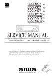
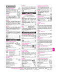
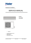
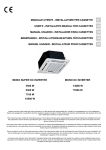
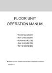
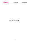
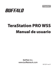
Haier air conditioner
Edition: 1.0-061128
Domestic
Air conditioner
HSU-12HA03/Z1
CAUTION
z
READ THIS MANUAL
CAREFULLY TO
DIAGNOSE TROUBLE
CORRECTLY BEFORE
OFFERING SERVICE.
z
THIS MANUAL IS USED
BY QUALIFIED
APPLIANCE
TECHNICIANS ONLY.
z
HAIER DOES NOT
ASSUME ANY
RESPONSIBILITY FOR
PROPERTY DAMAGE
OR PERSONAL INJURY
FOR IMPROPER
SERVICE
PROCEDURES DONE
BY ONE UNQUALIFIED
PERSON.
-1-
Haier air conditioner
Edition: 1.0-061120
CONTENTS
1. GENERAL INFORMATION................................................................3
2. SPECIFICATION................................................................................5
3. ELECTRICAL CONTROL..................................................................7
4. TROUBLE SHOOTING....................................................................13
5. INSTALLATION................................................................................15
6. WIRING DIAGRAM..........................................................................23
7. THERMISTER RESISTANCE CHART.............................................24
8. COMPRESSOR PERFORMANCE DIAGRAM................................30
9. SCHEMATIC DIAGRAM OF PCB....................................................31
-2-
Haier air conditioner
Edition: 1.0-061128
1. General information
This Service Manual describes the operation, disassembly, troubleshooting, and repair of Haier Room
Air Conditioners, etc. It is intended for use by authorized services who troubleshoot and repair these
units.
It is assumed that users of this manual are familiar with the use of tools and equipment used to
troubleshoot and repair electrical, mechanical, and refrigeration systems; and understand the
terminology used to describe and discuss them.
Haier urges you read and follow all safety precautions and warnings contained in this manual. Failure
to comply with safety information may result in severe personal injury or death.
Related Publications
This is a base service manual, covering a range of similar models. It is intended to be used in
conjunction with the Parts Manual and Technical Sheet covering specific model being serviced.
NOTE: General Precautions and Warnings
WARNING
To avoid risk of personal injury or death due to electrical shock, disconnect electrical power to unit
before attempting to service the unit.
WARNING
To avoid risk of personal injury or death due to electrical shock, DO NOT, under any circumstances,
alter the grounding plug .Air conditioner must be grounded at all times. Do not remove warning tag
from power cord. If a two-prong (non-grounding) wall receptacle is encountered, contact a qualified
electrician and have the receptacle replaced with a properly grounder wall receptacle in accordance
with the National Electrical Code.
WARNING
To avoid risk of heat exposure, which may cause death or severe illness, air conditioner must be
monitored when failures or shuts down.
WARNING
To avoid risk of personal injury or death due to electrical shock, grounding wires and wires colored like
grounding wires are NOT to be used as current carrying conductors. The standard accepted color
coding for ground wires is green or green with a yellow stripe. Electrical components such as the
compressor and fan motor are grounded through an individual wire attached to the electrical
component and to another part of the air conditioner. Grounding wires should not to be removed from
individual components while servicing, unless the component is to be removed and replaced. It is
extremely important to replace all removed grounding wires before completing service.
-3-
Haier air conditioner
Edition: 1.0-061128
IMPORTANT
INFORMATION
ƽҏFeatures
ƽҏComfortable: wide-angle airflow
ƽhealth air purifying
ƽquiet operation
ƽҏsuper energy efficient
MODEL: HSU-12HA03/Z1
ƽMain Specification
ƽCooling CapacityΚ 3450W
ƽRated Power/Current(cooling)Κ 1250W/6.0A
ƽEER: 2.76
ƽHeating CapacityΚ 3650W
ƽRated Power/Current(heating): 1280W/6.1A
ƽCOP: 2.85
ƽAir Volume(Indoor/outdoor):
445/-----
m3/h
ƽPower: 1PH 220V~ 50 Hz
- 4-
Haier air conditioner
Edition: 1.0-061120
2. Specification
Item
Model
Unit
Power
PH, V, Hz
Climate Type
A
Cooling Capacity
W
3450
Rated Power
W
1250
Rated Current
A
6.0
Max Power
W
1600
Max Current
A
7.0
W/W
2.70
Heating Capacity
W
3650
Rated Power
W
1280
Rated Current
A
6.1
Max Power
W
1650
Max Current
A
7.1
W/W
2.85
EER
Heating
1, 220, 50
T1
Starting Current
Cooling
HSU-12HA03/Z1
COP
Operating temp.
Cooling
℃
range
Heating
℃ 12~19
Indoor fan Velocity
H
rpm
1290
M
rpm
1150
L
rpm
1000
rpm
1060
Outdoor fan Velocity
3
Indoor Air Volume (High)
m
Max. pressure at warm side
Indoor Weight
Outdoor Weight
Indoor Dimension
Outdoor Dimension
450
MPa
-3
Moisture Removal
Noise Level
14~21
3
10 m /h
1.7
dB(A)
44/40/37
dB(A)
53
Net
Kg
8.6
Gross
Kg
10.6
Net
Kg
32
Gross
Kg
34
Net
mm
795*182*265
Package
mm
863*277*339
Net
mm
700*250*430
Package
mm
823*363*505
Indoor
(H/M/L)
Outdoor
Manufacture
Compressor
RECHI
Type
48R313NL-5ESF
Oil Charge
CC
Type
Refrigerant
2.65
----R22
Net Charge
Charge if over standard pipe
length
-5-
g
970
g/m
35
Haier air conditioner
Edition: 1.0-061120
Liquid pipe Diameter
mm
6.35
Gas pipe Diameter
mm
12.7
Standard length
m
3
Max length
m
15
Length
mm
580
Diameter
mm
25.5
Drainage pipe material diameter
mm
25.5
Refrigerant Pipe
Drain Hose
Remote Controller Model
YR-M07
Class of electric Shock Protection
I
Class of Water Proof
IP 24
3G2.5mm2
Power Cord (Model × Sectional Area)
-6-
Haier air conditioner
3. Electrical control
Edition: 1.0-061128
1. Basic Function
Description of function
Function
No.
1
Cooling
Set temperature 16℃-30℃æ
2
Drying
Set temperature 16℃-30℃¡æ
3
Heating (heat pump type)
Set temperature 16℃-30℃¡æ
4
Emergency run
Over 23℃¡æ cooling and set 26℃¡less
æ £23¡æ
℃ heating
»
and set 23℃¡æ
5
Test run
Set force cooling
6
Anti-cold wind (heat pump type)
When temperature of the heating pipe coil is low, low fan speed
or without airflow
7
Fan speed adjustment
Auto, high, middle, low four level fan speeds
8
Timer switch
24hours timer on, timer off, on-off, off-on
9
High load protection (heat pump type)
When heating in high ambient temperature to protect
compressor
10
Anti-freezing of the indoor unit
When heating in low ambient temperature to protect system
11
Defrosting run (heat pump type)
When heating in low ambient temperature to defrost for the
outdoor unit in order to make the system have a better efficiency
12
Self trouble shooting
Check the system trouble and give an alarm
13
Over current protection(heat pump type)
When working in high power to protect system
- 7-
Haier air conditioner
2.
Edition: 1.0-061128
Introduction to electrical control function
Including brief introduction to air conditioners of series models and electric
control function.
Brief introduction to electric control function
(1) Automatic running (applicable to fan-coil model)
When the running mode is turned to automation after starting the system, the
system will first determine the running mode according to the current room
temperature and then will run according to the determined mode. Tr in the following
selection conditions means room temperature, Ts means setting temperature, Tp
means temperature of indoor coil pipe
a. Tr>23OC
b. Tr<23OC
running refrigerating mode Ts=26 OC
running heating mode
Ts=23OC
After turning to the automation mode, the running mode can be switched
between refrigerating mode, fan mode and heating mode according to the change
of the indoor ambient temperature. But the automatic conversion between
refrigerating mode and heating mode must be conducted after 15 minutes.
(2) Indoor temperature control
Compressor OFF
Compressor ON
Heating
-1
+1
Compressor OFF
Refrigerating
Setting temperature
-1
+1
Setting temperature
(3) Dehumidification running
The compressor, outdoor fan and indoor fan will run as per the following
working pattern so as to realize the refrigerating running of
dehumidification:
a.Tr> Ts+2OC, compressor, outdoor fan run continuously, indoor fan runs as
per setting wind speed (State 1);
b.Ts+2OC>Tr>Ts, compressor, outdoor fan run intermittently with 10 minutes
ON, 6 minutes OFF. (Compressor and outdoor fan are synchronous)
indoor fan runs in fixed lower wind speed, and will cease at the standby time of 3 minutes (State 2)
c.Tr <Ts, compressor, outdoor fan ceases, indoor fan runs in lower wind
speed after 3 minutes ceases. (State 3)
- 8-
Haier air conditioner
Edition: 1.0-061128
State1
State2
State3
Ts-1
Ts
Ts+2
Ts+3
(4) Warm start (preventing cold wind when heating running begins,
applicable to fan-coil model))
When heating running begins, indoor fan will conduct the following fan
control:
a.If the temperature of indoor coil pipe is >23 O C, start lower wind
speed;
b.If the temperature of indoor coil pipe is >38 O C or the running time
of compressor> 4 minutes, turn to setting wind speed.
(5) Control of indoor fan under heating OFF state (applicable to fan-coil
model)
Under heating state, and the compressor cease; if the indoor coil pipeís
temperature Tp>23 O C, indoor fan will run in lower wind speed.
(6) Defrosting control (applicable to fan-coil model)
(1).Defrosting beginning condition:
O
a.After the state of Tp-Tr<18 C is continued for 5 minutes, the
accumulated running time of the compressor exceeds 45
minutes, the continuous running time of the compressor exceeds
20 minutes;
b.The accumulated running time of the compressor exceeds 3
hours, the continuous running time of the compressor exceeds
20 minutes, indoorunitís Tp <38 O C ;
c.The continuous running time of the compressor exceeds 20
minutes, the temperature of indoor coil pipe decreases 1
every 6 minutes, which lasts for more than 3 times, indoor unitís
Tp <38O C ;
d.When the indoor unit is in the state of overload protection and
the outdoor unit ceases, when the rerunning time of outdoor
unit exceeds10 minutes, the accumulated running time of the
compressor exceeds 45 minutes, the continuous running time
of the compressor is over 20 minutes, andTp <38O C ;
Defrosting will begin if one of the above conditions is met.
(2).Defrosting finishing condition:
a . If the defrosting time exceeds 9 (for 12 models)or 7 (for 07,09 models)
minutes, the original heating state will be resumed;
b. If the current of outdoor unitís compressor exceeds x.xA (different
models have different currents); defrosting will be finished if either
a or b is met.
- 9-
Haier air conditioner
Edition: 1.0-061128
Note: Sequence of defrosting actions:
9(or 7)minutes
Compressor ON
OFF
Four-way value ON
OFF
Outdoor fan
ON
OFF
55s
55s
1min
1min
(7) Freezing prevention function
Under refrigerating and dehumidifying state, the air conditioner will
control the outdoor fan as per the temperature Tp of the indoor coil
pipe according to the following conditions:
Zone of return deference
Compressor,outdoor fan OFF after 5 minutes
(8) 3 minutes stand-by time
0
Fan,compressor ON
7
Tp(OC)
When the compressor ceases due to the sensor OFF, unit On or OFF
or fault, it will maintain pause for 3 minutes.
(9) Overload protection during heating running
1.Temperature protection of indoor coil pipe: Under heating state, the
air conditioner will control the running of the fan as per the temperature
Tp of the indoor coil pipe and according to the following conditions:
a.65 OC<Tp, outdoor fan ceases; Tp<60 OC, outdoor fan resumes;
the time from ceasing to resuming is about 45 seconds;
b.72 OC<Tp, outdoor fan of compressor ceases after 5 seconds;
Tp<64 OC, compressor resumes after 3 minutes.
2.Current protection (different models have different protection currents):
a. When <current of compressor>(1), outdoor fan ceases; current
of compressor <(2), outdoor fan resumes;
b. When current of compressor>(3), compressor ceases.
(1)for 07 models the value is 3.6A,for 09 models the value is 4.0A,for 12 models the value is 5.2A
(2)for 07 models the value is 3.3A,for 09 models the value is 3.5A,for12 models the value is 4.6A
(3)for 07 models the value is 5.8A,for 09 models the value is 7.5A,for 12 models the value is 10.5A
(10) Compensatory function of power failure
If the unit is suddenly off during running due to power failure, or closed
for maintenance or troubleshooting, it will restart to run after the power
resumes with the original condition before the unit is off
- 10-
Haier air conditioner
Edition: 1.0-061128
Note: 1. Function setting: Pressing the SLEEP button on the remote control
unit for 10 times within 5 seconds until hearing 4 sounds from
the buzzer on the panel.
2. Memory content: Running mode, setting wind speed, setting
temperature, sleep state, flap state.
3. Cancellation of function: Pressing the SLEEP button on the
remote control unit for 10 times with in 5 seconds until hearing
2 sounds from the buzzer on the panel.
(11) Trial run function
When the air conditioner is in OFF state, press the emergency switch
for 5 seconds till hearing 2 sounds of click from the buzzer, then the
air conditioner will turn to the trial run state. The unit will run in the
refrigerating mode and the indoor fan will run in high wind speed mode.
(12) Emergency running mode
When the air conditioner is in stand-by state, press the emergency
switch till hearing a sound from the buzzer, then the air conditioner
will turn to the emergency run state. The rules of emergency run are
as follows:
a.Tr>23oC, running refrigerating mode, Ts = 26oC;
b.Tr<23o C , running heating mode , Ts = 23 o C .
(13) Temperature compensation
There is the function of automatic temperature compensation when
heating, with heating temperature setting = Ts(remote setting) + 4oC
(14) Sleeping function
a.After setting the sleeping function, the refrigerating mode and
dehumidification mode will run as per the following rules:
6hours
T( OC)
1hour
Ts+2
Ts+1
1hour
Ts
OFF
SLEEP
t(hour)
b.After setting the sleeping function, the heating mode will run as per the
following rules:
T( OC)
Ts
3hours
Ts-2
Ts-4
1hour
- 11-
3hours
Haier air conditioner
Edition: 1.0-061128
As shown in the above diagram,after running for 1 hour under refrigerating mode
and dehumidification mode,the setting temperature will increase 1 oC;after another
1 hour,it will increase 1 oC again,and after 6hours,it will cease;after running for
1 hour under heating mode, the setting temperature will decrease 2 oC, after another
1 hour,it will decrease the 2oC again,and after 3 hours,it will increase 1 oC,and after
other 3 hours,it will cease.
MODEL
PCB
HSU-12HD03/R2
0010404012
HSU-09HD03/R2
HSU-07HD03/R2
0010404012
0010403257A
The SW2 select “25”OR “35”
35
25
25
- 12-
Haier air conditioner
Edition: 1.0-061128
4. Trouble shooting
Before asking for service, check the following first.
Phenomenon
The system does not
restart immediately.
Normal
Performance
inspection
Noise is heard.
Cause or check points
z
When unit is stopped, it won't restart immediately
until 3 minutes have elapsed to protect the system.
z
When the electric plug is pulled out and reinserted,
the protection circuit will work for 3 minutes to
protect the air conditioner.
z
During unit operation or at stop, a swishing or
gurgling noise may be heard. At first 2-3 minutes
after unit start, this noise is more noticeable. (This
noise is generated by refrigerant flowing in the
system.)
During unit operation, a cracking noise may be
heard. This noise is generated by the casing
expanding or shrinking because of temperature
changes.
z
z
Should there be a big noise from air flow in unit
operation; air filter may be too dirty.
z
This is because the system circulates smells from
the interior air such as the smell of furniture,
cigarettes.
z
During COOL or DRY operation, indoor unit may
blow out mist. This is due to the sudden cooling of
indoor air.
z
z
Is power plug inserted?
Is there a power failure?
z
Is fuse blown out?
z
Is the air filter dirty? Normally it should be cleaned
every 15 days.
Are there any obstacles before inlet and outlet?
Is temperature set correctly?
Are there some doors or windows left open?
Is there any direct sunlight through the window
during the cooling operation?(Use curtain)
Smells are generated.
Mist or steam is blown
out.
Multiple
check
Does not work at all.
Poor cooling
z
z
z
z
Are there too much heat sources or too many
people in the room during cooling operation?
- 13-
Haier air conditioner
Light indication
Power
★
★
■
★
Time
■
□
□
□
Run
Reason
Ways and means
Edition: 1.0-061128
Solution
Tools
■
The sensor of
indoor ambient
temperature is
abnormal
Examine the sensor of indoor
ambient temperature,if the
resistance value is 0 , or ∞,
the sensor is abnormal.
Replace the
sensor.
Multimeter
□
The
temperature
sensor of
indoor coil pipe
is abnormal
Examine the temperature
sensor of indoor coil pipe, if the
resistance value is 0, or ∞ ,
the sensor is abnormal.
Replace the
sensor.
Multimeter
★
Optical SCR or
indoor PC
board is
abnormal
Check whether indoor motor
has 80~170V voltage, if it has,
wiring bund is normal, then
check whether the optical SCR
is good, replace it if it is has
flaw; else check whether there
are something wrong with
connecting line, indoor motor
capacitor and coil assembly.
Replace the
optical SCR,
indoor PC
board, or
indoor motor
capacitor.
Multimeter
★
EEPROM is
abnormal
Check whether the EEPROM is
installed properly.
Replace the
EEPROM.
Electric
iron and
Multimeter
- 14-
Haier air conditioner
Edition: 1.0-061128
5. Installation
Read this manual before installation
Explain sufficiently the operating means to the user
according to this manual.
Necessary Tools for Installation
1.Driver
2.Hacksaw
3.Hole core drill
4.Spanner(17,19 and 26mm)
5.Torque wrench(17mm,22mm,26mm)
6.Pipe cutter
7.Flaring tool
8.Knife
9.Nipper
10.Gas leakage detector or
soap-and-water solution
11.Measuring tape
12.Reamer
Drawing for the installation of indoor and outdoor units
Accessory parts
1
2
Accessory parts
Remote controller
Number
of
articles
1
2
1
3
Mounting plate
1
4
6
7
4X50
Steel nail, cement
4X25
Screw
Plastic cap
Drain-elbow
Parts name
mo
A
Non-adhesive tape
B
Adhesive tape
re th
an
C
Saddle(L.S) with screws
D
E
Connecting electric cable
for indoor and outdoor
Drain hose
F
Heating insulating material
10c
m
mo
re th
an
Drain hose
5
Optional parts for piping
Mark
R-03 dry battery
more than 5cm
No.
6
G
Piping hole cover
10c
m
Attention must be paid to
the rising up of drain hose
A
4
1
Arrangement of piping directions
8
Cover
1
Rear
right
Left
9
Cushion
C
Rear left
4
re
Pipe supporting plate
an
re th
tha
n1
10c
mo
0c
Below
10
m
mo
Right
m
1
Note:Cooling only units don't have Drain-elbow
D
E
more
than
60cm
more
than
15c
m
The marks from A to G in the figure are the parts numbers.
The distance between the indoor unit and the floor should be
more than 2m.
- 15-
Haier air conditioner
Edition: 1.0-061128
280
INSTALLATION
140
415
140
9.Nipper
10.Gas leakage detector or
soap-and-water solution
11.Measuring tape
Floor fixing dimensions
of the outdoor unit
(Unit:mm)
Fixing of outdoor unit
12.Reamer
Fix the unit to concrete or block with bolts( 10mm) and nuts firmly and horizontally.
When fitting the unit to wall surface, roof or rooftop, fix a supporter surely with nails
or wires in consideration of earthquake and strong wind.
If vibration may affect the house, fix the unit by attaching a vibration-proof mat.
Indoor Unit
Selection of Installation Place
Place, robust not causing vibration, where the body can be supported
sufficiently.
Place, not affected by heat or steam generated in the vicinity, where
inlet and outlet of the unit are not disturbed.
Place, possible to drain easily, where piping can be connected with the
outdoor unit.
Place, where cold air can be spread in a room entirely.
Place, nearby a power receptacle, with enough space around. (Refer
to drawings).
Place where the distance of more than lm from televisions, radios,
wireless apparatuses and fluorescent lamps can be left.
In the case of fixing the remote controller on a wall, place where the
indoor unit can receive signals when the fluorescent lamps in the room
are lightened.
Outdoor Unit
Place, which is less affected by rain or direct sunlight and is
sufficiently ventilated.
Place, possible to bear the unit, where vibration and noise are
not increased.
Place, where discharged wind and noise do not cause a
nuisance to the neighbors.
Place, where a distance marked
is available as illustrated
in the above figure.
Power Source
Before inserting power plug into receptacle, check the voltage without fail. The power source is the same as the corresponding name plate.
Install an exclusive branch circuit of the power.
A receptacle shall be set up in a distance where the power cable can be reached. Do not extend the cable by cutting it.
Selection of pipe
To this unit, both liquid and gas pipes shall be insulated
as they become Iow temperature in operation.
Use optional parts for piping set or pipes covered with
equivalent insulation material.
The thickness of the pipe must be 0.8 mm at least.
HSU-12HA03/Z1
Liquid pipe(
Gas pipe(
- 16-
)
)
6.35mm(1/4")
12.7mm(1/2")
Haier air conditioner
Edition: 1.0-061128
Indoor unit
1.Fitting of the Mounting Plate and Positioning of the wall Hole
When the mounting plate is first fixed
1.Carry out, based on the neighboring pillars or lintels, a proper leveling for the plate to be
fixed against the wall, then temporarily fasten the plate with one steel nail.
2. Make sure once more the proper level of the plate, by hanging a thread with a weight from
the central top of the plate, then fasten securely the plate with the attachment steel nail.
3. Find the wall hole location A using a measuring tape
A=145mm
30mm
B= 60mm
When the mounting plate is fixed side bar and lintel
Fix to side bar and lintel a mounting bar, Which is separately sold, and then fasten
the plate to the fixed mounting bar.
Refer to the previous article, "
position of wall hole.
When the mounting plate is first fixed ", for the
2.Making a Hole on the Wall and Fitting the Piping Hole Cover
Make a hole of 60 mm in diameter,
slightly descending to outside the wall.
Install piping hole cover and seal it
off with putty after installation
Indoor side
Wall hole
60mm
Outdoor side
Thickness
of wall
(Section of wall hole) G Piping hole pipe
3.Installation of the Indoor Unit
Drawing of pipe
[ Rear piping ]
Draw pipes and the drain hose, then fasten them with the adhesive tape
[ Left
Left-rear piping ]
In case of left side piping, cut away, with a nipper, the lid for left piping.
In case of left-rear piping, bend the pipes according to the piping direction to the mark of hole for left-rear
piping which is marked on heat insulation materials.
- 17-
Haier air conditioner
Edition: 1.0-061128
Indoor unit
1. Insert the drain hose into the dent of heat insulation materials of indoor unit.
2. Insert the indoor/outdoor electric cable from backside of indoor unit, and pull it out on the front side, then
connect them.
3. Coat the flaring seal face with refrigerant oil and connect pipes.
Cover the connection part with heat insulation materials closely, and make sure fixing with adhesive tape
Heat insulation
material
Lid for right piping
Lid for left piping
Lid for under piping
Drain hose
Piping
Indoor/outdoor
electric cable
Fix with adhesive tape
Indoor/outdoor electric cable and drain hose must be bound with refrigerant piping by protecting tape.
[Other direction piping]
Cut away, with a nipper, the lid for piping according to the piping direction and then bend the pipe according
to the position of wall hole. When bending, be careful not to crash pipes.
Connect beforehand the indoor/outdoor electric cable, and then pull out the connected to the heat insulation
of connecting part specially.
Fixing the indoor unit body
Hang surely the unit body onto the upper notches of the
mounting plate. Move the body from side to side to verify
its secure fixing.
In order to fix the body onto the mounting plate,hold up
the body aslant from the underside and then put it down
perpendicularly.
4.Connecting the indoor/outdoor Electric Cable
Removing the wiring cover
Remove terminal cover at right bottom corner of indoor unit, then
take off wiring cover by removing its screws.
When connecting the cable after installing the indoor unit
1. Insert from outside the room cable into left side of the wall hole, in which
the pipe has already existed.
2. Pull out the cable on the front side, and connect the cable making a loop.
- 18-
Edition: 1.0-061128
Haier air conditioner
INSTALLATION
Indoor unit
When connecting the cable before installing the indoor unit
Insert the cable from the back side of the unit, then pull it out on the front side.
Loosen the screws and insert the cable ends fully into terminal block, then tighten the screws.
Pull the cable slightly to make sure the cables have been properly inserted and tightened.
After the cable connection, never fail to fasten the connected cable with the wiring cover.
Note: When connecting the cable, confirm the terminal number of indoor and outdoor units carefully. If wiring
is not correct, proper operation can not be carried out and will cause defect.
1. If the supply cord is damaged, it must be replaced by the manufacturer or its service agent or a similar
qualified person. The type of connecting wire is H05RN-F or H07RN-F.
2. If the fuse on PC board is broken please change it with the type of T. 3.15A/250V.
3. The wiring method should be in line with the local wiring standard.
4. After installation, the power plug should be easily reached.
5. A breaker should be incorporated into fixed wiring. The breaker should be all-pole switch and the
distance between its two contacts should be not less than 3mm.
YEL/GRN
4
BRN
RED
WHT
BLK
RED
5G1.0mm2
4
Indoor unit
WHT
BLK
YEL/GRN
BRN
- 19-
Outdoor unit
Haier air conditioner
Edition: 1.0-061128
INSTALLATION
Outdoor unit
Outdoor unit
1.Installation of Outdoor Unit
Install according to
Drawing for the installation of indoor and outdoor units
2.Connection of pipes
To bend a pipe, give the roundness as large as possible not to crush the pipe
Connecting the pipe of gas side first makes working easier.
The max vertical distance between the indoor unit and the outdoor unit is 5 m.
Half union
Flare nut
Forced fastening without careful centering
may damage the threads and cause a
leakage of gas.
Pipe Diameter (
Spanner
Torque wrench
)
Fastening torque
Liquid side 6.35mm(1/4")
18N.m
Gas side 9.52mm(3/8")
40N.m
Gas side 12.7mm(1/2")
55N.m
Gas side 15.88mm(5/8")
60N.m
Be careful that matters, such as wastes of sands, etc. shall not enter the pipe.
3.Connection
Use the same method on indoor unit. Loosen the screws on terminal block and insert the plugs fully into
terminal block, then tighten the screws.
Insert the cable according to terminal number in the same manner as the indoor unit.
If wiring is not correct, proper operation can not be carried out and controller may be damaged.
Fix the cable with a clamp.
4.Attaching Drain-Elbow
If the drain-elbow is used, please attach it as
figure. (Note: Only for heat pump unit.)
- 20-
Haier air conditioner
Edition: 1.0-061128
INSTALLATION
Outdoor unit
5.Purging Method:
Push the air out of the indoor unit
and piping as followes:
(1) Remove the valve cap on 2-way
valve in outdoor unit.
2-way valve
6.35mm(1/4")
(2) Loosen by 1/2 turn the flare nut of
gas pipe, which is conneted to
3-way valve.
3-way valve
12.7mm(1/2")
o
(3) Loosen 2-way valve by 90 using
hexagon wrench, and after approx.
10 sec tighten it up. Gas comes out
through flare nut on wide pipe. If no
gas is discharged, tighten flare nut
with specified torque.
HSU-12HA03/Z1
(4) Open 2-way and 3-way valves
using specified torque.
(5) Tighten the caps on the valves
with specified torque.
Tighten torque N.m
Valve rod
7-9
Valve cap
20-25
When connecting pipe exceeds 5 meters, 16g refrigerant shall be added
per exceeding meter. Charge according to the following list.
Piping length
5m
7m
10m
Additional amount
No need
32g
80g
Note: When extending piping, air inside piping shall be removed by using external
refrigerant gas, charge according to the following list.
Brand new outdoor unit is charged 50g more refrigerant than regulated weight.
Only for first installation, this extra 50g can be used to purge air in pipes.
During this procedure, 50g refrigerant will be discharged in piping.
o
(This must be strictly controlled within 90 and 10 sec.)
- 21-
Haier air conditioner
Edition: 1.0-061128
INSTALLATION
1.Power Source Installation
The power source must be exclusively used for air conditioner. (Over I0A)
In the case of installing an air conditioner in a moist place, please install an
earth leakage breaker.
For installation in other places, use a circuit breaker as far as possible.
2.Cutting and Flaring Work of Piping
Pipe cutting is carried out with a pipe cutter and burs must be removed.
After inserting the flare nut, flaring work is carried out.
A
Pipe diameter(
6.35mm(1/4")
) Size A(mm)
0.8~1.5
Gas side
9.52mm(3/8")
12.7mm(1/2")
1.0~1.8
1.2~2.0
Gas side
15.88mm(5/8")
1.4~2.2
Liquid side
Gas side
Flare tooling die
Incorrect
Correct
Lean Damage of flare Crack
Partial
Too outside
3.On Drainage
Please install the drain hose so as to be downward slope without fail.
Please don't do the drainage as shown below.
Less than 5cm
It becomes high
midway.
The end is immersed
in water.
It waves.
The gap with the ground
is too small
There is the bad smell
from a ditch
Please pour water in the drain pan of the indoor unit, and confirm that drainage is
carried out surely to outdoor.
In case that the attached drain hose is in a room, please apply heat insulation
to it without fail.
Check for Installation and Test Run
Please kindly explain to our customers how to operate through the instruction manual.
Check Items for Test Run
Gas leak from pipe connecting?
Heat insulation of pipe connecting?
Are the connecting wirings of
indoor and outdoor firmly inserted
to the terminal block?
Is the connecting wiring of indoor
and outdoor firmly fixed?
Put check mark
in boxes
Is drainage securely carried out?
Is the earth line securely
connected?
Is the indoor unit securely fixed?
Is power source voltage abided
by the code?
Is there any noise?
- 22-
Is the lamp normally lighting?
Are cooling and heating (when
in heat pump) performed normally?
Is the operation of room temperature
regulator normal?
Haier air conditioner
Edition: 1.0-061128
6. WIRING DIAGRAM WIRING DIAGRAM
WIRING DIAGRAM FOR INDOOR UNITS ;
7363696
@
@
WIRING DIAGRAM FOR OUDOOR UNITS ;
W
B
R
@
BR
@
( )
@
B
@
@@
B
W
W
B
R
B
M
M
BR
W
B :
B(C)
R(S)
R:
W:
BR:
W(R)
Y/G:
NOTE:
1.wiring as above for cool-heat models.
2.The dotted lines are needn't in cooling only models(marked with @) .
Wire is connected from BR (marked with
@@) on terminal block to W.
3.The O.L.P. may needn't in some models for different compressor - 23 -
Haier air conditioner
Edition: 1.0-061120
7. Thermistor resistance chart
Room temperature sensor
T(℃)
-20
-19
-18
-17
-16
-15
-14
-13
-12
-11
-10
-9
-8
-7
-6
-5
-4
-3
-2
-1
0
1
2
3
4
5
6
7
8
9
10
11
12
13
14
15
16
17
R(KΩ)
251.8
236.9
223.1
210.1
197.9
186.5
175.9
165.9
156.5
147.7
139.5
131.8
124.5
117.7
111.3
105.3
99.63
94.3
89.3
84.58
80.14
75.96
72.02
68.31
64.81
61.51
58.39
55.45
52.68
50.06
47.58
45.24
43.02
40.93
38.95
37.08
35.31
33.63
- 24 -
Haier air conditioner
18
19
20
21
22
23
24
25
26
27
28
29
30
31
32
33
34
35
36
37
38
39
40
41
42
43
44
45
46
47
48
49
50
51
52
53
54
55
56
57
58
59
60
61
Edition: 1.0-061120
32.04
30.53
29.1
27.75
26.47
25.25
24.1
23
21.96
20.97
20.03
19.14
18.3
17.49
16.73
16
15.3
14.65
14.02
13.42
12.85
12.31
11.79
11.3
10.83
10.39
9.96
9.553
9.165
8.794
8.441
8.103
7.78
7.472
7.178
6.897
6.628
6.371
6.125
5.889
5.664
5.449
5.243
5.046
- 25 -
Haier air conditioner
62
63
64
65
66
67
68
69
70
71
72
73
74
75
76
77
78
79
80
Edition: 1.0-061120
4.857
4.676
4.502
4.336
4.177
4.024
3.878
3.738
3.603
3.474
3.35
3.231
3.117
3.008
2.903
2.802
2.705
2.611
2.522
Indoor pipe temperature sensor
T(℃)
-30
-29
-28
-27
-26
-25
-24
-23
-22
-21
-20
-19
-18
-17
-16
-15
-14
-13
-12
-11
-10
R(KΩ)
155.4
146.4
138.1
130.2
122.9
116
109.5
103.5
97.77
92.44
87.42
82.71
78.29
74.12
70.21
66.52
63.06
59.79
56.71
53.81
51.08
- 26 -
Haier air conditioner
-9
-8
-7
-6
-5
-4
-3
-2
-1
0
1
2
3
4
5
6
7
8
9
10
11
12
13
14
15
16
17
18
19
20
21
22
23
24
25
26
27
28
29
30
31
32
33
34
Edition: 1.0-061120
48.5
46.07
43.77
41.6
39.55
37.62
35.79
34.06
32.43
30.88
29.42
28.03
26.72
25.48
24.3
23.18
22.12
21.12
20.17
19.26
18.4
17.59
16.81
16.08
15.38
14.71
14.08
13.48
12.91
12.36
11.84
11.35
10.88
10.43
10
9.592
9.204
8.833
8.479
8.141
7.819
7.511
7.217
6.936
- 27 -
Haier air conditioner
35
36
37
38
39
40
41
42
43
44
45
46
47
48
49
50
51
52
53
54
55
56
57
58
59
60
61
62
63
64
65
66
67
68
69
70
71
72
73
74
75
76
77
78
Edition: 1.0-061120
6.668
6.411
6.166
5.931
5.707
5.492
5.287
5.09
4.902
4.722
4.549
4.383
4.225
4.073
3.927
3.788
3.654
3.525
3.402
3.283
3.17
3.061
2.956
2.855
2.759
2.666
2.577
2.491
2.408
2.329
2.253
2.179
2.108
2.04
1.975
1.912
1.851
1.193
1.737
1.682
1.63
1.58
1.531
1.484
- 28 -
Haier air conditioner
79
80
81
82
83
84
85
86
87
88
89
90
Edition: 1.0-061120
1.439
1.395
1.353
1.313
1.274
1.236
1.2
1.164
1.13
1.098
1.066
1.035
- 29 -
Haier air conditioner
Edition: 1.0-061128
8. COMPRESSOR PERFORMANCE DIAGRAM
Performance Curve
Model
48R313N
Power Supply
220-240V / 50Hz / 1PH
Run Capacitor
30 μF / 370 VAC
Capacity (Kcal/Hr)
35 C
Return Gas Temperature
8.3 C
Subcooling
35 C
Ambient Temperature
Cond. Temperature
3100
2950
2800
2650
2500
2350
2200
2050
1900
1750
1600
45℃
50℃
55℃
60℃
Power (Watts)
0
1
Current (Amps)
3
4
5
6
7
8
9
10
11
12
1000
970
940
910
880
850
820
790
760
730
700
60℃
55℃
50℃
45℃
0
1
2
3
4
5
6
7
8
9
10
11
12
4.70
4.55
4.40
4.25
4.10
3.95
3.80
3.65
3.50
3.35
3.20
60℃
55℃
50℃
45℃
0
Flow (Kg/Hr)
2
1
2
3
4
5
6
7
8
9
10
11
12
70.0
67.0
64.0
61.0
58.0
55.0
52.0
49.0
46.0
43.0
40.0
50℃
60℃
0
1
2
3
4
5
6
7
8
9
10
11
12
Evaporating Temperature(℃)
Dwg. Name
Curves OF Compressor
- 30-
Dwg. No.
48R313N
Haier air conditioner
Edition: 1.0-061128
9. Schematic diagram of PCB
CIRCUIT DIAGRAM
CH1
+5V
D5
+12V
1
4007
4007
D4
4007
C1
RV1
104/250V
N
IC6
Vin
R5
C6
D6
4148
R7
102
C2
104
C17
104
D10
4148
D7
4148
D8
4148
D9
4148
R2
CX3
103
R1
A057R
+5V
R43
PG
11
FLZ
24
R32
104
ROOM
100
29
560
POW
TIM
RUN
IR
27
26
25
13
R35
R34
R33
R22
560
560
560
10K
CT
C11
104
30
HEAT
E5
R20
31
7
E4
4.7u/50V
IC2
1
2
3
4
A
B
C
D
A0 VCC
A1
WP
A2 SCL
GND SDA
R
10K
+5V
8
7
6
5
HEAT
+12V
L
D11
4007
K2
100
R24
+12V
YAJI
9013
RESET
K1
T3.15A
FUSE
IC3
YAJI
+12V
5
4
3
2
1
C12
104
220UF/16V
4.7K
E7
CH3
1
ROOM
10K
C9
104
+5V
4.7u/50V
D12
4148
1
2
3
4
5
6
7
R45
N6
104
R38
R36
1K
3.3K/1%
20K/1%
R37
E6
CH6
FLZ
+5V
POW
TIM
RUN
IR
GND
C4
102
PIPE
+5V
C10
1K
4
3
2
1
HP2
4.7K
50HZ
1
C16
390
E3
100UF/16V
RP1
R39
CH4
PIPE
14
10K
N
IC1
4.7K
1K
R3
1
2
3
CX2
PG
10K
R6
CH9
120
R44
200
220UF/16V
N1
TA1
L
IC3
R46
E2
C3
104
9013
10K
P2
9012
+5V
3
Vout
104
1000UF/25V
TRANS
+5V
7805
E1
1
D3
4007
1
4007
R4
23
27
+12V
4.7UF/16V
100
FLZ
22
R11
ST
21
R14
100
BUZZ
20
R13
100
O_FAN
28
R12
100
FLZ1
8
X1
K3
1
D2
GND
D1
CH2
CX1
2
L
+12V
XT1
8M
24C01A
N2
STEPMOTOR
9
10
X2
GND
3
4
SCL
SDA
15
STEPA
R8
4.7K
+12V
BZ1
K5
CH8
N5
9013
9013
9013
+5V
R41
10K
N4
19
STEPB
9013
R29 10K
18
STEPC
R40
10K
R27
2003
COM
R28 10K
R30 10K
SW1
3.3K
17
STEPD
16
NC
K4
R9
NEWFAN
C7
R31 3.3K
SW2
R15
3.3K
R18
3.3K 35
25
R16
3.3K
R17
3.3K
104
2
R21
R10
4.7K
1K
+12V
10K
P1
+12V
2SB1182/3CG892
C19
+5V
SW3
TX
1
2
3
+12V
R19 10K
N3
BUZZER
32
NFAN2
VDD
1
104
A
B
C18
104
NEWFAN
+5V
R26
10K
R25
10K
C14
104
5
SW1
6
XT
12
PG_BACK
C15
104
+5V
R42 51K
CH5
3
2
1
PG_BACK
R23
10K
C5
103
富士通N202小分体原理图
C13
103
- 31 -
Haier air conditioner
Haier Group
Haier Industrial Park, No.1, Haier Road
266101, Qingdao, China
http://www.haier.com
- 32-
Edition: 1.0-061128