1
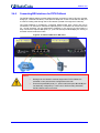
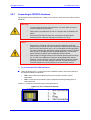
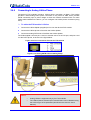
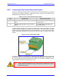
Installation Manual 2.4.7 2. Installing the Device Connecting to FXS/FXO Interfaces The procedure below describes the cabling of the device's FXS and FXO module analog interfaces. Warnings: • To protect against electrical shock and fire, use a 26 AWG min wire to connect FXO ports to the PSTN. • FXO ports are considered to be TNV-3; FXS ports are considered to be TNV-2. • Ensure that FXS and FXO ports are connected to the appropriate, external devices; otherwise, damage to the device can occur. • FXO (Foreign Exchange Office) is the interface replacing the analog telephone and connects to a Public Switched Telephone Network (PSTN) line from the Central Office (CO) or to a Private Branch Exchange (PBX). The FXO is designed to receive line voltage and ringing current, supplied from the CO or the PBX (just like an analog telephone). An FXO VoIP device interfaces between the CO/PBX line and the Internet. • FXS (Foreign Exchange Station) is the interface replacing the Exchange (i.e., the CO or the PBX) and connects to analog telephones, dial-up modems, and fax machines. The FXS is designed to supply line voltage and ringing current to these telephone devices. An FXS VoIP device interfaces between the analog telephone devices and the Internet. Notes: ¾ To connect the FXS /FXO interfaces: Using the device's RJ-11 connectors on the FXS/FXO module, connect the device to the required telephone interfaces: • FXS: connect the FXS module's ports to fax machines, modems, and/or telephones. • FXO: connect the FXO module's ports to telephone exchange analog lines or PBX extensions. The RJ-11 connector pinouts are shown in the figure below: Figure 2-11: RJ-11 Connector Pinouts Version 6.2 21 February 2011