1
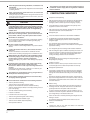
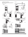
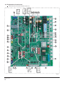
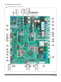
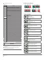
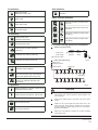
S3 definition
6
21
Night silent mode
(Default the Factory Set)
6
21
Silent mode
6 21
Reserve
ENC3 and S12 definition
(1&
6
21
S10 definition
6 21
Super silent mode
6
21
(1&
6 21
None silent mode
( 1& 6
21
S5 definition
Setting the numbers of indoor units
to be 0-15
Setting the numbers of indoor units
to be 16-31
Setting the numbers of indoor units
to be 32-47
6
21
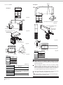
Heating priority mode
(Default the Factory Set)
( 1& 6
21
6
21
Cooling priority mode
6
21
number 63 & the more operating
mode first
6
21
Respond the heating mode only
Respond the cooling mode only
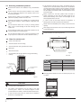
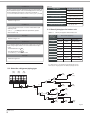
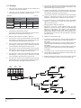
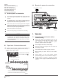
Outdoor unit power wiring
Outdoor unit
Leakage
Manual
power supply
protector
switch
Indoor unit power wiring
Fig.6-6
Indoor power
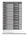
S6 definition
Leakage protector
Manual switch
6
21
6.5 Electric wiring system and installation
380-415V 3N~ 50Hz
6
21
Setting the numbers of indoor units
to be 48-63
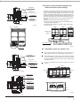
Branch box
Automatic search address
6
21
6
21
Nonautomatic search address.
(The communication way of the original
indoor units) (Default the Factory Set)
Clean the indoor unit address
(Effective to automatic searching new
indoor units)
Indoor unit
S7 definition
Fig.6-7
6
21
6
21
Without setting the numbers of indoor units
(Default the Factory Set)
Need to set the numbers of indoor units
S8 definition
6
21
For DC Fan+AC Fan
6
21
For DC Fan+DC Fan
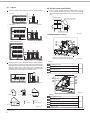
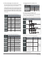
CAUTION
Set refrigerant piping system, signal wires between
indoor-indoor unit, and that between outdoor-outdoor unit
into one system.
Power must unified supply to all indoor units in the same
system.
Please do not put the signal wire and power wire in the
same wire tube; keep distance between the two tubes.
(Current capacity of power supply: less than 10A--300mm,
less than 50A--500mm.)
Make sure to set address of outdoor unit in case of parallel
multi-outdoor units.
Installation manual
19