1
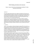
S. & A.S. LTD ELEVATOR CONTROL MODULE AUTOMATIC PUSH BUTTON MICROZED-A REF. E-SMOKY V3.04 USER’S MANUAL FOR S/W VERSION B304300 ( Decimal / Gray / Binary/ Enhanced code Indicator) (Taxi / Collective Board) 1516 Beirut Office: Boutros Building 1st Basement Cheikh-el-Ghabi Street Ghabi Beirut 2068 7808 Lebanon Tel: +961 1 216 994 Fax:+961 1 339 600 Headquarters & Factory: S. & A. S. Building Seaside Road Jieh Chouf Lebanon Tel: +961 7 996 333 Fax:+961 7 996 116 Website: www.sascontrollers.com Technical Support & Email: Tel: +961 71 996 333 [email protected] 2 1. GENERAL DESCRIPTION 1.1 MAIN FEATURES ............................................................................................................................. 3 1.2 TECHNICAL DATA ........................................................................................................................... 3 2. TERMINAL DESCRIPTION 2.1 TERMINAL LAYOUT......................................................................................................................... 4 2.2 INPUT TERMINALS .......................................................................................................................... 4 2.3 OUTPUT TERMINALS ...................................................................................................................... 5 2.3.1 OUTPUT TERMINALS FOR AC 1 SPEED AND AC 2 SPEED 2.3.2 OUTPUT TERMINALS FOR HYDRAULIC 2.4 CALL TERMINALS............................................................................................................................ 6 3. DIP SWITCHES AND PUSH BUTTON 3.1 DIP SWITCHES FUNCTION DESCRIPTION.................................................................................... 7 3.2 ON BOARD DISPLAY AND PUSH BUTTONS FUNCTION DESCRIPTION ..................................... 7 3.2.1 ON-BOARD CALL REGISTRATION FUNCTION 3.2.2 ON-BOARD INSPECTION OPERATION 3.3 DIP SWITCHES AUXILIARY FUNCTIONS MENU............................................................................ 8 3.3.1 CODE MENU 4. VIEWING ERRORS AND ERROR CODE DESCRIPTION 4.1 HOW TO VIEW THE ERRORS ......................................................................................................... 9 4.2 HOW TO CLEAR THE ERRORS ...................................................................................................... 9 4.3 ERROR CODE DESCRIPTION ........................................................................................................ 9 5. INSTALLATION GUIDE 6. APPENDIX A 3 4 5 5 7 7 7 9 9 10 10 3 1. GENERAL DESCRIPTION 1.1 MAIN FEATURES Platform Type Self diagnostic On-board display Push buttons Error count Shaft information Indicator signal Number of stops Door type Door controls4 Door status6 Floor Stop time Car light Inspection mode PTC Input Universal Outputs Terminals Microcontroller AC 1 speed – AC 2 speed – Hydraulic1 – VVVF Error codes describing common faults related to periphery inputs A three digit 7-segment display is used for floor, error messages and menu Three push buttons used to access different parameter and the menu Count of fatal errors is displayed End of shaft in the up direction End of shaft in the down direction Slow down and final stop in the up direction Slow down and final stop in the down direction Car position is saved following a power failure2 Decimal – Positive common (one output per floor) or 7-Segment – Positive common Gray Code or Binary Code or Enhanced Code(when using S.&A.S. scrolling display) 10 stops or 7 stops for Gray or Binary registered calls or 5 stops for Enhanced or decimal indicator with Collected calls or 7 stops for Gray collected calls Swinging or automatic door3 Input for re-open, photocell and door jam switch + input to bypass closing delay5 Parking with door opened or door closed7 Variable from 0 to 9.9 seconds8 Automatic switch off after delay - 0 to 9.9 seconds9 For installation and maintenance purposes using slow speed10 (bypasses all shaft information) Motor PTC input halts lift operation when motor overheats Indicator outputs are suitable for both common positive and common negative All terminals are individually labeled according to function to facilitate identification 1.2 TECHNICAL DATA Supply voltages Inputs Control outputs Call terminals Indicator outputs Connection 1 Board supply: 17vac +15% -25% - 120mA Periphery supply: 22vdc +15% -25% Each input has a led to indicate its status – all inputs are optically isolated Input active voltage level is 22vdc Each output has a led to indicate its status – all outputs are optically isolated Each output is capable of driving the negative side of a contactor or relay coil operating 11 from a dc voltage as high as 90 volts with currents as high as 3 amperes Each call has a led to indicate its status Call active voltage level is 22 volts (P) For registered calls: Each car call terminal consists of a combined input/output which is optically isolated Car call terminals are capable of driving lamps up to 3 watts operating on 22vdc Each car call terminal is protected by an additional output transistor Each output has a led to indicate its status – all outputs are optically isolated LED On: Output voltage level is 0vdc (GND) LED Off: Output voltage level is 22vdc (P) Screw type, plug-in connectors Selection by DIP switch, refer to section 3.1. When power returns, elevator resumes from where it was without the need of a homing trip. Selection by DIP switch, refer to section 3.1. 4 For automatic door only. 5 Activated by a push button in the car. 6 For automatic door only. 7 Selection by presetting parameters in the auxiliary functions menu, refer to section 3.3. 8 Selection by presetting parameters in the auxiliary functions menu, refer to section 3.3. 9 Selection by presetting parameters in the auxiliary functions menu, refer to section 3.3. 10 Activated by an external key switch and two push buttons. 11 Care should be taken to add a freewheeling diode in parallel with the coil of each contactor or relay driven from the board. Failure to do so will jeopardize the operation of the output transistor and will eventually damage it. 2 3 4 2. TERMINAL DESCRIPTION F6 F5 F4 F3 F2 F1 F0 LOW SPD HIGH SPD UP DIR DN DIR F9 F8 F7 P GND STAR LGHT OPEN CLSE CAM 2.1 TERMINAL LAYOUT ON 1 2 3 4 LS EC INSP EN INSP UP INSP DN 17VAC A 17VAC B EOS UP EOS DN SFTY ON RE OPN CLSENDLY LS EO C3 C2 C1 C0 SDFS UP SDPF DN C9 C8 C7 C6 C5 C4 PTCA PTCB PUSH BUTTONS 2.2 INPUT TERMINALS SDFS_UP SDPF_DN EOS_UP EOS_DN SFTY ON RE_OPN CLSE_NDLY LS_EO LS_EC INSP_EN INSP_UP INSP_DN 17VAC A 17VAC B PTC A PTC B Slow down and final stop in the up direction Slow down and final stop in the down direction End of shaft in the up direction End of shaft in the down direction Should be active when lift is moving Re-open for automatic door (when inactive) / door closed for swinging door (when active) Bypasses reclosing delay in automatic door Limit switch end of opening Limit switch end of closing Inspection enable (when input is inactive) Inspection up Inspection down Board power supply – 17vac a Board power supply – 17vac b Input from the PTC Input from the PTC 5 2.3 OUTPUT TERMINALS 2.3.1 OUTPUT TERMINALS FOR AC 1 SPEED AND AC 2 SPEED P +22V GND STAR LIGHT OPN CLSE_CAM LOW_SPD HI_SPD UP_DIR DN_DIR Biasing voltage from periphery supply – positive side1 Biasing voltage from periphery supply – negative side1 Spare output Car light relay Open door relay or contactor2 Cam contactor3 / Close relay or contactor2 Low speed contactor High speed contactor Up direction contactor Down direction contactor 2.3.2 OUTPUT TERMINALS FOR HYDRAULIC P +22V GND STAR LIGHT OPN CLSE_CAM LOW_SPD HI_SPD UP_DIR DN_DIR Biasing voltage from periphery supply – positive side1 Biasing voltage from periphery supply – negative side1 Star output Car light relay Open door relay or contactor2 Cam contactor3 / Close relay or contactor2 Releveling relay High speed valve Pump delta contactor Down direction valve 2.3.3 INDICATOR OUTPUT TERMINALS FOR MICROZED-A4-8 F9 F8 F7 F6 F5 F4 F3 F2 F1 F0 Floor 9 output4 / Not Used8 Floor 8 output4 / Not Used8 Floor 7 output4 / Not Used8 Floor 6 output4 / g output8 Floor 5 output4 / f output8 Floor 4 output4 / e output8 Floor 3 output4 / d output8 Floor 2 output4 / c output8 Floor 1 output4 / b output8 Floor 0 output4 / a output8 2.3.4 INDICATOR OUTPUT TERMINALS FOR MICROZED-A5-6-7 F9 F8 F7 F6 F5 F4 F3 F2 F1 F0 1 Floor information D5 / Floor information C6-7 5 6-7 Floor information C / Floor information B 5 6-7 Floor information B / Floor information A Floor information A5 / Call 6 output6-7 5 6-7 Not used / Call 5 output 5 Not used / Call 4 output6-7 Not used5 / Call 3 output6-7 5 6-7 Not used / Call 2 output 5 Not used / Call 1 output6-7 Not used5 / Call 0 output6-7 Although this is not an output, it is listed with the outputs for convenience. For automatic door only. For swinging door. 4 For Decimal.opr=dec. 5 For Gray or Binary code indicator not registered calls.opr=gnr or bnr 6 For Gray or Binary code indicator registered calls.opr=gr or br 7 For Collective 7 floors with gray code indicator.opr=cL7 8 For seven segment display indicator. Opr=7Sd 2 3 6 2.3.5 INDICATOR OUTPUT TERMINALS FOR OPR = COL1 F9 F8 F7 F6 F5 F4 F3 F2 F1 F0 Floor 4 output Floor 3 output Floor 2 output Floor 1 output Floor 0 output Call 4 output Call 3 output Call 2 output Call 1 output Call 0 output 2.3.6 INDICATOR OUTPUT TERMINALS FOR OPR = ENH2 F9 F8 F7 F6 F5 F4 F3 F2 F1 F0 2.4 CALL TERMINALS C9 C8 C7 C6 C5 C4 C3 C2 C1 C0 1 Up Arrow Down Arrow Floor information C Floor information B Floor information A Call 4 output Call 3 output Call 2 output Call 1 output Call 0 output Floor 9 call / Not Used1-2-3 Floor 8 call / Not Used1-2-3 Floor 7 call / Not Used1-2-3 Floor 6 call / Not Used1-2 Floor 5 call / Not Used1-2 Floor 4 call Floor 3 call Floor 2 call Floor 1 call Floor 0 call For collective calls and decimal indicator .opr=coL For collective calls and enhanced scrolling display. opr=EnH 3 For Collective 7 floors with gray code indicator.opr=cL7 And For Gray or Binary code indicator registered calls.opr=gr or br 2 7 3. DIP SWITCHES AND PUSH BUTTON 3.1 DIP SWITCHES FUNCTION DESCRIPTION For any change made to the DIP switches to take effect (except DIP switch 3), the power has to be turned OFF and then ON again. Alternatively, changes of the DIP switches can be made when the power is OFF. ON 1 2 3 4 Should be kept OFF: Reserved to access the auxiliary functions menu described in section 3.3 OFF = Enable PTC ON = Disable PTC Selects operating mode: OFF = AC1 or AC2 speed ON = Hydraulic Selects door type: OFF = Automatic door ON = Swinging door 3.2 ON BOARD DISPLAY AND PUSH BUTTONS FUNCTION DESCRIPTION Three push buttons are used to simplify the access of the main menu. The first page in the menu displays the status of the elevator. The following three pages are used to access the historical of faults. The last page is used to initiate a homing trip. The NEXT and PREV buttons are respectively used to scroll downwards and upwards in the five pages menu. SELECT is used to access the function or information within the menu item. No functions are associated with the first item in the menu (i.e. Page 1). The following table describes the Main Menu along with all its functions: Page Display Description FL# Normal operation with floor displayed on the right. The floor is replaced by a downward scrolling minus sign “-“ when elevator is making a homing trip. 1 1 In# Inspection mode with floor displayed on the right. The floor is replaced by a downward (default) scrolling minus sign “-“ when elevator is making a homing trip. E## Error detected with error code displayed on the two digits on the right. SELECT displays the most recent error in memory. The error code is displayed on two leftmost digits and the floor on which the error occurred is displayed on the rightmost digit. The error code and the floor are separated by a decimal point. noE is displayed if Err 2 there are no errors in memory. PREV displays the previous error in memory. If no previous errors exist, the display returns to Err. NEXT displays the errors in memory in the opposite direction of PREV. SELECT displays the count of level II errors in memory2. noF is displayed if there are no Fer 3 level II errors. SELECT clears all errors from memory. don is displayed to indicate the completion of ErA 4 this task. Htr SELECT initiates a homing trip 5 3.2.1 ON-BOARD CALL REGISTRATION FUNCTION The operator can give calls using the push buttons to test the lift. The display has to be on Page 1. Lift has to be in normal operation with no faults. The display shows FL#. Press SELECT, the display will show Fr# with # blinking. Use the PREV and NEXT push buttons to change the floor selection. Once the desired floor is displayed, press SELECT push button. The call for this floor is registered and the appropriate led will light on the board as well as in the car. The lift will proceed to serve this call. If no buttons are pressed in 5 seconds, the # will stop blinking and will show the floor information. To exit the call registration mode, press the SELECT push button for 3 seconds. The board will also exit the call registration mode if no buttons are pressed for 1 minute. 3.2.2 ON-BOARD INSPECTION OPERATION When in inspection mode, NEXT and PREV push button act as INSP_DN and INSP_UP inputs respectively. The INSP_DN and INSP_UP inputs have higher priority and will override the NEXT and PREV push buttons. 1 2 If any other page is selected, page 1 is automatically restored if no push buttons are pushed for 10 seconds. Refer to sections 4.1 and 4.3. 8 3.3 DIP SWITCHES AUXILIARY FUNCTIONS MENU To access the auxiliary functions menu: 1. Turn the power off. 2. Set DIP switch 4 to on. 3. Turn the power back on (elevator will become inactive). 4. Using NEXT and PREV push buttons go to the menu item you desire to edit or change. 5. Press SELECT to edit the parameter associated with the menu item. 6. Use INC and DEC push buttons to make the desired change. 7. Press OK to enter the new value in memory. 8. To modify another parameter repeat from step 4. 9. To end parameter editing, set DIP switch 4 to off (elevator will become active again). Display Lgt FLt LdF Ldt Description Selects the parking mode for automatic door: OPn = Parking door opened CLd = Parking door closed Sets the car light time Sets the floor stopping time Sets the landing floor Sets the landing time Ado The automatic door is considered jammed after this delay CJd Sets the car jammed delay In case Hydraulic is not selected, sets the STR output function: gong, intermediate speed1 (used in VVVF operation) or base block (used in VVVF operation) Sets the start time in hydraulic mode. If hydraulic is not selected, it selects VVVF and sets the start delay: Zero: AC2-speed is selected (StP has to be set to zero as well) Positive value: VVVF selected with direction engaging before speed reference Negative value: VVVF selected with speed reference engaging before direction Selects VVVF and sets the Stop delay: Zero: AC2-speed is selected (Str has to be set to zero as well) Positive value: VVVF selected with speed reference disengaging before direction Negative value: VVVF selected with direction disengaging before speed reference Sets the re-leveling option in hydraulic mode Enables the EOS during the inspection Enables Power-on homing Sets the operating mode dEc = Decimal floor information output – 10 stops gr = Gray code floor information output with registered calls (using A, B, C) – 7stps gnr = Gray code floor information output (using A, B, C, D) – 10 stops br = Binary code floor information output with registered calls (using A, B, C)-7stps bnr = Binary code floor information output (using A, B, C, D) – 10 stops 7Sd = Seven segment display information output – 10 stops EnH = Enhanced scrolling display information output with collected calls (using A, B, C ,Up arrow, Down arrow) – 5 stops coL = Decimal floor information output with collected calls – 5 stops cL7 = Gray code floor information output with collected calls (using A, B, C) – 7 stps Re-open Logic Permanent Close Press push button to access CODE MENU2 PAr SPr Str StP rLL EoS PoH oPr roP PCL Cod 1 Range Opn - CLd 0 - 25.0 sec 0 - 25.0 sec non, 0 - 9 1 – 99 min Dis, 1 to 255sec Dis, 1 to 255sec gng, Int, bbL -9.9 to 9.9 sec -9.9 to 9.9 sec ALL – SEL DiS – EnA DiS – EnA dEc gr – gnr br – bnr 7Sd EnH coL cL7 nc - no DiS – EnA When the intermediate speed is selected, the SPR is engaged when the destination is just one floor away. Note that once lift has initiated travel to a destination further that the next floor (SPR not engaged), calls received from the next floor will not be served in the current trip. 2 Refer to section 3.3.1 for details on accessing CODE MENU. 9 3.3.1 CODE MENU A blank screen appears with a decimal point on the first digit. Use the INC and DEC push buttons to set the first digit of the code. Use OK to enter it. The digit is instantaneously replaced by “c”. A decimal point on the second digit prompts you to enter the second digit of the code by repeating the above procedure. Repeat this process until all six digits are entered. If you make a mistake in any digit, follow through till the end and then repeat from the beginning. If the code is correct, you will be able to access the following menu: Display StA ELA DAy out Description Selects the status of the code lock feature Displays the count of the number of days elapsed Pressing INC or DEC push buttons resets counter to zero Displays the preset number of operating days Press SELECT push button to exit code menu Range DiS – EnA N/A 0 to 999 N/A 4. VIEWING ERRORS AND ERROR CODE DESCRIPTION 4.1 HOW TO VIEW THE ERRORS Faults detected by the board are divided into three kinds: 1. Level I faults: faults that block the elevator when they occur. But the elevator can resume operation right after the fault disappears. 2. Level II faults: faults that can be tolerated for a few occurrences before the elevator is blocked by the board. The count of level II faults can be accessed in page 3 of the main menu. When the count of level II faults reaches 10, the board will block the elevator. 3. Level III faults: faults that the board considers to be fatal and will consequently block any further operation of the elevator. The last 10 errors can be viewed on page 2 of the main menu1. 4.2 HOW TO CLEAR THE ERRORS To clear the errors as well as the count of level II faults from memory, go to page 4 of the main menu and press the SELECT button. Refer to section 3.2. 4.3 ERROR CODE DESCRIPTION Error Level 2 I Safety circuit and/or door opened during travel 21 2 I Door lock circuit opened during travel 214 2 22 224 234 I I II II Safety circuit failed to close after door closing Failure in locking door after 3 attempts Failure in closing door Failure in opening door Whenever EOS info does not correspond to the floor, a homing trip is done with no fault registered Shaft information fault EOS-UP and EOS-DN faults (both open) Motor has been powered for “CJd” time, car did not move Motor has overheated (indicated by the PTC input), lift stops at nearest floor Preset number of operating days expired 20 24, 25 1 N/A8 26 28 29 II III III 34 I 35 III Description Action taken Cancel calls and wait 5 sec before accepting new calls and resuming travel Waits for lock circuit to close, cancels calls if fault persists more than 5sec3 Cancels calls and opens door3 3 Cancels calls Cancels calls, opens door3 Close door and resume N/A Performs a homing trip Blocks elevator6 Blocks elevator5 Waits until motor cools down Blocks elevator7 Refer to section 3.2. For swinging door. Waits for a call to resume operation. 4 For automatic door. 5 After repairing the faulty part, erase the faults. Refer to section 3.2. 6 When the cause of the fault is diagnosed and fixed, the elevator will automatically resume operation. 7 To recover from error 35, access code menu and clear the count of elapsed days. Refer to sections 3.3 and 3.3.1. 8 N/A means not assigned. 2 3 10 5. INSTALLATION GUIDE Step 1 Install and wire the panel according to wiring diagrams provided by the panel assembler. Double check all connections. Step 2 Make sure that the board is in the Inspection Mode (Inspection switch should be opened). Power the panel. The display of the board may show a downward scrolling minus sign. This is normal and it indicates that the board does not have a previous car position in memory. As soon as the elevator is switched from inspection to normal operation, it will make a homing trip and display will show FL0 when the elevator reaches the first stop. Regardless of what is on the display, if all safety circuits are closed, inspection up and inspection down push buttons are active (therefore inspection travel only requires the closing of safety circuit). Below is a visual indication of what the status of the input LEDs should be so that the elevator operates in the inspection mode: SDFS SDFS EOS EOS SFTY RE CLSE LS LS INSP INSP INSP UP DN UP DN ON OPN NDLY EO EC EN UP DN Automatic door1 (Door open) Automatic door (Door closed) Swinging door Status Irrelevant Input Inactive (OFF) Input Active (ON) Step 3 Using the elevator in the inspection mode, adjust the position of all magnets according to the layout provided on the MicroZed-A v3.04 WIRING DIAGRAM – INPUTS (SHEET 2 of 6), refer to section 6. APPENDIX A. If you are using bi-stable magnetic switches, proceed with inspection travel to terminal floors to properly set their contacts. When you finish, and prior to changing the operating mode from inspection to normal, the inputs should look as follows (given that elevator is on any intermediate floor and on floor level): SDFS SDFS EOS EOS SFTY RE CLSE LS LS INSP INSP INSP UP DN UP DN ON OPN NDLY EO EC EN UP DN Automatic door Swinging door Status Irrelevant Input Inactive (OFF) Input Active (ON) Refer to section 3.3 to set all internal parameters according to the site’s requirements. Refer to section 3.1 to set DIP switches according to the site’s requirements. Change operating mode from INSPECTION to NORMAL. Elevator should proceed with its homing trip and will stop on the floor level of the first floor. 6. APPENDIX A This appendix contains all wiring diagrams relevant to assembling the board in a panel. 1 When an inspection up or down is given, board proceeds by closing the door before moving. Door is then kept closed. 1 D 2 3 B304V1W1 B304V1W1.Sch B304V1W2 B304V1W2.Sch B304V1W4 B304V1W4.Sch B304V1W5 B304V1W5.Sch B304V1W7 B304V1W7.Sch B304V1W8 B304V1W8.Sch 4 5 6 B304V1W3 B304V1W3.Sch D B304V1W6 B304V1W6.Sch C C MICROZED A AC2SPEED WIRINGS B B A A Size B FCSM No. Scale DWG No. Rev Sheet 0 of 0 1 2 3 4 5 6 1 R S 2 3 4 5 6 T 5 AC + 2 (22V) PP (22V) 1 + 0 + 3 1 TRANSFORMER P 5 Amps 17 AC D - 3300UF 50V 3300UF 50V D GND 6 4 2 BRIDGE L1 0 0 AC + 60 AC - 2 (60V) 1 P3 L2 2 1 380 END OF TRAVEL UP BRIDGE L3 Ch 0 2 Amps BRAKE 4 Cu 3 6 5 END OF TRAVEL DOWN 17 CL 4 R Cd 3 6 5 N SPEED GOVERNOR (PARACHUTE) GND C LIGHT SWITCH EXTERNAL CAR STEP MICROSWITCH C EMERGENCY STOP 10 3 1 3 1 DOOR CONTACTS SWINGING DOOR 3 AUTO. DOOR Rd Cd Cu LOCK CONTACTS GND Cd 21 21 P3 21 2 1 4 2 4 2 Rlight Cu Cl 22 22 Cu Cl Ch B 17V 17V 5 3 1 5 3 1 GND (-) LGHT 6 2 U1 4 6 W2 V1 4 W1 2 V2 UP DIR CAR LIGHT RELAY Ch U2 Cl P +22V DN DIR UP DIRECTION CONTACTOR DOWN DIRECTION CONTACTOR A2 A2 A2 A2 10 Cd A1 A1 Rlight B A1 GND A1 P 2 22 CAR LIGHT LOW SPD HIGH SPD SLOW SPEED CONTACTOR HIGH SPEED CONTACTOR MICROZED A V3.04 BOARD S. & A.S. Ltd. BOUTROS BLDG, 1ST BSMT CHEIKH-EL-GHABY ST. 2068 7808 GHABY - BEIRUT MH MICROZED A WIRING DIAG:SUPPLY & OUTPUTS A A MOTOR Size B FCSM No. Scale DWG No. B304V1W1.Sch Rev 1 Sheet 1 of 8 1 2 3 4 5 6 1 2 LAST STOP 3 4 5 6 LAST STOP 5CM 5CM D D 5CM 5CM 15CM SWINGING DOOR 21 22 A1 A1 A2 Cc A2 END OF CLOSING REOPEN Co 1 4 4 Rd END OF OPENING CLOSE WITHOUT DELAY Cu A2 Cd Co 22 DOOR JAM SWITCH A1 Cc 3 BISTABLE MAGNETIC SWITCHES MONOSTABLE MAGNETIC SWITCHES THMH 3 PP 3 PP C PHOTOCELL 5CM FIRST STOP P3 Cc ON=NORMAL OFF=INSPECTION (REVISION) 5CM FIRST STOP P 21 OVERWEIGHT SWITCH P C AUTOMATIC DOOR P3 OVERWEIGHT SWITCH P B B PTC a PTC b SDFS SDFS UP DN EOS UP EOS DN SDFS SDFS UP DN EOS UP EOS DN SFTY ON INSP UP INSP DN INSP EN RE OPN CLSE CAM RE OPN CLSE NDLY LS EO LS EC OPN CLSE CAM MICROZED A V3.04 BOARD S. & A.S. Ltd. BOUTROS BLDG, 1ST BSMT CHEIKH-EL-GHABY ST. 2068 7808 GHABY - BEIRUT Note: 1- Use the Monostable Magnetic Switches configuration for Automatic door. MICROZED A WIRING DIAG: INPUTS / DOOR INFO A A Size B FCSM No. Scale DWG No. B304V1W2.Sch Rev 1 Sheet 2 of 8 1 2 3 4 5 6 1 2 3 P 4 5 6 P Rlight C 9 9 8 8 7 7 6 6 5 5 4 4 3 3 2 2 1 1 0 0 D CAR CALLS LAND CALLS D C P DIGITAL INDICATOR C9 C8 C7 C6 C5 C4 C3 C2 C1 C0 F0 F1 F2 F3 F4 F5 F6 F7 F8 F9 B B MICROZED AG V3.04 BOARD S. & A.S. Ltd. BOUTROS BLDG, 1ST BSMT CHEIKH-EL-GHABY ST. 2068 7808 GHABY - BEIRUT opr="dEc" MICROZED AG MICROZED A WIRING DIAG: CALLS / FLOOR INFORMATION A A Size B FCSM No. Scale DWG No. B304V1W3.Sch Rev 1 Sheet 3 of 8 1 2 3 4 5 6 1 2 3 4 P 5 6 P Rlight CC6 D D 6 6 CC5 5 5 4 4 CC3 3 3 CC2 2 2 CAR CALLS LAND CALLS CC4 CC1 1 1 CC0 C C 0 0 P GRAY / BINARY CODE DISPLAY C C9 C8 C7 C6 C5 C4 C3 C2 C1 C0 F0 F1 F2 F3 F4 F5 F6 F9 B F8 A F7 B B MICROZED AP V3.04 BOARD S. & A.S. Ltd. BOUTROS BLDG, 1ST BSMT CHEIKH-EL-GHABY ST. 2068 7808 GHABY - BEIRUT opr="CL7" or opr=" gr" or opr=" br" MICROZED AP MICROZED A WIRING DIAG: CALLS / FLOOR INFORMATION A A Size B FCSM No. Scale DWG No. B304V1W4.Sch Rev 1 Sheet 4 of 8 1 2 3 4 5 6 1 2 3 P 4 5 6 P Rlight C 9 9 8 8 7 7 6 6 5 5 4 4 3 3 2 2 1 1 0 0 D CAR CALLS LAND CALLS D C P GRAY / BINARY CODE DISPLAY D C9 C8 C7 C6 C5 C4 C3 C2 C1 C0 F9 C F8 B F7 A F6 B B MICROZED AP V3.04 BOARD S. & A.S. Ltd. BOUTROS BLDG, 1ST BSMT CHEIKH-EL-GHABY ST. 2068 7808 GHABY - BEIRUT opr=" gnr" or opr="bnr" MICROZED AP MICROZED A WIRING DIAG: CALLS / FLOOR INFORMATION A A Size B FCSM No. Scale DWG No. B304V1W5.Sch Rev 1 Sheet 5 of 8 1 2 3 4 5 6 1 2 3 4 P 5 6 P Rlight D D 4 CC3 3 3 CC2 2 2 CAR CALLS LAND CALLS CC4 4 CC1 1 1 CC0 C 0 C 0 P DIGITAL INDICATOR 0 1 2 3 4 C9 C8 C7 C6 C5 C4 C3 C2 C1 C0 F0 F1 F2 F3 F4 F5 F6 F7 F8 F9 B B MICROZED APG V3.04 BOARD S. & A.S. Ltd. BOUTROS BLDG, 1ST BSMT CHEIKH-EL-GHABY ST. 2068 7808 GHABY - BEIRUT opr="CoL" MICROZED APG MICROZED A WIRING DIAG: CALLS / FLOOR INFORMATION A A Size B FCSM No. Scale DWG No. B304V1W6.Sch Rev 1 Sheet 6 of 8 1 2 3 4 5 6 1 2 3 4 P 5 6 P Rlight D D 4 CC3 3 3 CC2 2 2 CAR CALLS LAND CALLS CC4 4 CC1 1 1 CC0 C 0 C 0 P S. & A.S. Enhanced display C C9 C8 C7 C6 C5 C4 C3 C2 C1 C0 F0 F1 F2 F3 F4 F9 F8 F7 B F6 A F5 B B MICROZED APGE V3.04 BOARD S. & A.S. Ltd. BOUTROS BLDG, 1ST BSMT CHEIKH-EL-GHABY ST. 2068 7808 GHABY - BEIRUT opr="EnH" MICROZED APGE MICROZED A WIRING DIAG: CALLS / FLOOR INFORMATION A A Size B FCSM No. Scale DWG No. B304V1W7.Sch Rev 1 Sheet 7 of 8 1 2 3 4 5 6 1 2 3 P 4 5 6 P Rlight D 9 8 8 7 7 6 6 5 5 4 4 3 3 CAR CALLS LAND CALLS D 9 C C P B 2 2 1 1 0 0 C9 C8 C7 C6 C5 C4 C3 C2 C1 C0 1 2 3 4 5 6 7 F0 F1 F2 F3 F4 F5 F6 F7 F8 DPY a a b c f b g d e e c d f g [LEDgn] B F9 MICROZED AG V3.04 BOARD S. & A.S. Ltd. BOUTROS BLDG, 1ST BSMT CHEIKH-EL-GHABY ST. 2068 7808 GHABY - BEIRUT opr="7Sd" MICROZEd A MICROZED A WIRING DIAG: CALLS / FLOOR INFORMATION A A Size B FCSM No. Scale DWG No. B304V1W8.Sch Rev 1 Sheet 8 of 8 1 2 3 4 5 6