1
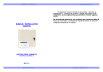
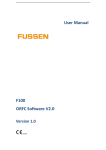
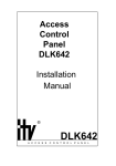
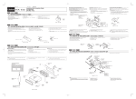
LHD6003-8
INSTALLATION
MANUAL
Manufacturer: Longhorn Industrial co.,Ltd.
Add: Longhorn Hi-Tech Estate, TongFuyu
Industrial Avenue, Longhua, Shenzhen
G. D. China
Post number: 518109
Telephone: 800 830 8196
Fax: +86-755-28140429
Web address: http://www.long-horn.com
E-mail: [email protected]
CONTENTS
Wiring connections diagram.................................................. 1
System overview and installation........................................... 2
System overview............................................................. 2
Cabinet of control installation........................................... 2
Earth ground................................................................... 2
Battery........................................................................... 2
Transformer.................................................................... 2
Power supply terminal..................................................... 3
Audible output terminal.................................................... 3
Accessorial power output terminal.................................... 3
DK802 keypad installation............................................... 3
Loop input terminal.......................................................... 5
The 8th protection zone..................................................... 6
Anti-tamper switch mounting............................................ 6
mounting steps............................................................... 6
Telephone line and telephone set installations................... 7
Function default................................................................... 7
Keypad operation instructions............................................... 8
Programming item................................................................ 9
Function setting.................................................................. 11
Programming conversions.............................................. 11
Installer code................................................................ 12
Operator arming type and operator code.......................... 12
Arming/password option................................................ 13
Communication format................................................... 14
Communication control.................................................. 16
User 1#......................................................................... 17
Receiver 1# phone number............................................. 18
User 2#......................................................................... 19
Receiver 2# phone number............................................. 19
RPS Phone Number....................................................... 20
Loop report code........................................................... 21
Loop control.................................................................. 22
Soft zone A................................................................... 23
Soft zone B................................................................... 24
Soft zone C................................................................... 25
Event report.................................................................. 26
Test report.................................................................... 27
Arming/disarming report code......................................... 28
Duress report and delay................................................. 29
Hearing/seeing switch................................................... 30
Unit control................................................................... 31
Loop switch................................................................... 32
Test report countdown timer............................................ 33
Table of LHD6003-8 system function default......................... 34
Technical parameters......................................................... 42
WIRING CONNECTIONS DIAGRAM
Black
Watchdog
light
Connect
battery
Red
AC AC A/AUX GND AUX BELL GND KEY+ DATA CLK Z1 GND Z2
Z5 GND Z6
Z7 GND Z8 LT LR TT
TR
Telephone Telephone
wire
turn off power
supply
Black
Red
Green
Write
Assistant
attachment
Can't turn
off power
supply
Z3 GND Z4
GND
KEY+
DATA
CLK
Alarm
Keypad
1. SYSTEM OVERVIEW AND INSTALLATION
System Overview
Thank you for choosing LHD6003-8 security system developed by
Longhorn company in Shenzhen. We will introduce main function
and how to install the system and set system function in this Guide.
If you want to know the system further, please refer to LHD6003-8
User Guide or alarm receiver and interrelated software operation
guide.
Cabinet of Control Installation
The system should be mounted in a location which allows
convenient access to AC power, telephone line, and earth ground.
Earth Ground
To ensure the effectiveness of the lightning and transient protection
circuits, the control panel must be connected to "Earth Ground".
Ideally, this should be common ground to the power lines,
telephone system, and security system. This type of ground, called
a "Unified Earth Ground", provides the best protection. The ground
connection, from a grounding rod, cold water pipe or other
established ground to the panel housing.
Battery
LHD6003-8 system uses 12V/7.0Ah sealed lead-acid
rechargeable battery as back-up. Red line contact
anode and black line contact cathode in the system.
Fuse F4 offers short circuit protection. Connect the
red lead to the positive terminal of the battery and the
black lead to the negative battery terminal.
Transformer
The system uses 220VAC input,15V/2A output
transformer at 50Hz which supplies power only for
the master controller. If an AC power failure lasts
more than 15 minutes, the keypads will display a
system trouble and an AC failure report will be sent,
if programmed. When AC restored for 5 minutes, the
restoral report will be sent.
2
Battery
12V 7.0Ah
Sealed Lead-acid charge
Power Supply Terminal
The maximum total power available at BELL, SW/AUX, AUX and
KEY+ terminals is 800mA; The combined power for AUX power,
all keypads and the 8th protection zone do not exceed 500mA.
Audible Output Terminal
The BELL terminal(Audible output) provides up to
0.6A at 10.5~13.5VDC. Programming for bell time
and drive voltage mode(fixed,pulse and chirp ).The
BELL terminal is protected by a 2.5A/3.5AG, fastblow fuse F1.If any fuse opens, remove AC and DC
power, remove the short or overload condition, then
replace the fuse before restoring power. Do not
substitute a higher rated fuse.
Accessorial Power Output Terminal
The SW/AUX terminal provides a positive
10~14VDC for auxiliary devices that require
switched power for resetting. Typical devices include
glass break and smoke detectors. AUX terminal
provides uninterrupted power supply. The SW/AUX
and AUX terminals are protected by a 750mA/3AG,
fast-blow fuse F2. If any fuse opens, remove AC and
DC power, remove the short or overload condition,
then replace the fuse before restoring power. Do not
substitute a higher rated fuse.
DK802 Keypad Installation
Blocks on Terminal Plate
DATA: Data line between master controller and keypad.
CLK: Clock line between master controller and keypad.
KEY+: Provide a 11~14VDC power for keypad. It is
protected by a 750mA/3AG, fast-blow fuse F3. If any
fuse opens, remove AC and DC power, remove the short
or overload condition, then replace the fuse before
restoring power. Do not substitute a higher rated fuse.
TAMPER: Provide tamper protection for keypads.
3
TAMPER
Wiring
connection
entrance
KEY+ GND DATA CLK
Terminal plate
Connections between patch board and controller: connect
KEY+, CLK, DATA and GND in the panel of control to KEY+,
CLK, DATA and GND in the keypad respectively, TAMPER on
the terminal plate contact input terminal of protection zone in
the controller as a circuit loop, wire length is up to 152m if
you use 22AWG (0.643mm)copper core.
Connection between terminal plate and keypad: use
connection wire with two connectors, one connector plugs in
interface on the back of keypad, and the other plugs in
interface of terminal plate.
Retainer notch
Retainer
notch
Spring hole of
Interface
anti-tamper switch notch
Buzzer
holes
Connection wire
The system can connect four DK802 keypads at most.
Keypad mounting: press spring of anti-tamper switch in the
spring hole, then hang the keypad on installed steadier and
ensure the spring pressed tightly by fixed steadier .
4
80
120
10.6
Fixed
steadier
33
Bracket
30
20
(Unit
mm)
Installation sketch
Loop Input Terminal
Connection:
N.O. Alarm
N.C. Alarm
N.O. Alarm
system
N.C. Alarm system
C
C
N.C. Loop
N.O. Loop
Each loop can connect an open loop switch or a closed loop switch or
a 2.2k end-of-line EOL resistor and program respectively. If the
system is in armed status, any open loop or short circuit will be
alarmed on the condition of EOL loop programming; open loop will
trigger fault signal in despite of system in any status on the condition
of monitor loop programming.
5
Attached list
Zone1 Zone7
0
5.6VDC
Zone8
Short circuit
0
12.5VDC
Short circuit
5.6 8.1VDC
Normal
12.5 12.8VDC
Normal
8.1 14.0VDC
Open loop
12.8 14.0VDC
Open loop
th
The 8 Protection Zone
It is not only used as protection zone, but also supply 10~12.5V DC/
25mA power for glass break and smoke detector etc .
Anti-tamper Switch Mounting
LHD6003-8 system has two anti-tamper switches, one is used to
protect front cover of control, the other is used to protect cabinet of
control.
Anti-tamper switch
for cover
Anti-tamper switch
for cabinet
mounting steps:
1. install anti-tamper switches on the top right corner inside cabinet of
control. The contact of anti-tamper switch for cover should be up,
and the contact of anti-tamper switch for cabinet should be down.
Please refer to the sketch below:
Cover
anti-tamper
switch
box
anti-tamper
switch
F4 3A
BATTERY
Black
battery
F3 750mA
ALARM
F1 2.5A
KEYPAD
F2 750mA
ASSISTANT
ATTACHMENT
Red
AC AC SW/AUX GND AUX BELL GND KEY+ DATA CLK
IC1
Watchdog
light
Z1 GND Z2
Z3 GND Z4
Z5 GND Z6
Battery
12V 7.0Ah
Sealed Lead-acid charge
6
Z7 GND
Z8
LT
LR
TT
TR
K1
2. Connect anti-tamper switch for cover and anti-tamper switches for
box in series, then connect a protection zone.
3. Programming for protection zone according to actual requirement.
Telephone Line and Telephone Set Installations
LT, LR connect telephone line; TT, TR connect telephone set.
2. Function Default
Type
Default
Type
Default
Guest code
Disabled
Loop 1
Entry/exit delay, EOL circuit
Dialling type
Dual-tone
Loop 2
Doors and windows,
EOL circuit
RPS allowed
Yes
Loop 3
Doors and windows,
EOL circuit
Installer code
012345
Loop 4
Doors and windows,
EOL circuit
Default installer code
Yes
Loop 5
Interior, EOL circuit
Operator 2# ~8# code
Disabled
Loop 6
Interior, EOL circuit
Operator 1# code
(master)
1234
Loop 7
24 hour emergency or
anti-tamper, EOL circuit
Test report interval
7days/
disabled
Loop 8
Fire or smoke-supervised
EOL circuit
Bell time
5 minutes
Local system
Entry time 60 seconds and prewarning
Yes
Exit time
30 seconds and prewarning
Dynamic battery test
Off
Report
disabled
Soft protection zone
enable
Note: If you want to know detailed default above, you can refer to
Table of LHD6003-8 system function default in the end of guide.
7
3.Keypad Operation Instructions
Function
Keystroke Sequence
Entry unit programming
Exit unit programming
System disarming
System arming
Immediate arm stay
Arm stay
Immediate arming
Shunt protection zone
Chime on/off
Clear alarm memory
Fire
burglary
Panic
Press and hold fire alarm key 3s
Press and hold burglary alarm key 3s.
Press and hold panic key 3s.
Control unit reset
Control unit on/off
AUX power reset
Battery test
Bell test
Walk test
Center station test
Note: More operation instructions and detailed operation
explanations can be consulted in user guide.
8
4. Programming Item
Programming option
Instruction address
Data bit
Installer Code
00
1~6
Operator Code(Operator 1#~8#)
01~08
2~6
Master Code(Operator 1#)
01
2~6
Guest Code(Operator 8#)
01
2~6
Operator Arming Type
01~08
1
Guest Code Using Time
09
1
Password Instruction
09
2
Operator Code Default Option
09
3
Arming Type
09
4
User 1#
0C
1~6
User 2#
10
1~6
Receiver 1# Receive Format
0A
1
Receiver 1# Message Format
0A
2
Receiver 1# Phone Number
0D~0F
1~6
3
Receiver 2# Receive Format
0A
Receiver 2# Message Format
0A
4
Receiver 2# Phone Number
11~13
1~6
Keypad RPS Enable (hold)
0B
3
RPS Enable(hold)
0B
4
RPS Phone Number (hold)
14~16
1~6
Local System Only
2F
1
Loop Receiver Select
1F~26
1
Loop Response Time
1F~26
2
Loop Restore Type
1F~26
3
Loop Arming Type
1F~26
4
Loop Audible Type
1F~26
5
Loop Circuit Type
1F~26
6
9
Instruction address
Data bit
Loop Alarm Report Code
Programming option
17~1E
1~2
Door Chime Enable
30~37
1
Loop Delay Before Dial Time
30~37
4
Loop Restore Report Code
17~1E
3~4
Loop Shunt Enable
30~37
2
Loop Shunt Report Code
17~1E
5~6
Loop Shunt Receiver Select
2A
1
Group Shunt Enable
30~37
3
Soft Zone Operation Enable
2F
4
4 Minutes Power-on Delay Enable
2F
3
Entry Prewarning Enable
2E
1
Exit Prewarning Enable
2E
2
Entry Delay Time
2D
3
Exit Delay Time
2D
4
Fire Audible Type
28
4
Fire Report Code
28
1~2
Fire Report Receiver Select
28
3
Burglary Audible Type
29
4
Burglary Report Code
29
1~2
Burglary Report Receiver Select
29
3
Panic Audible Type
27
4
Panic Report Code
27
1~2
Panic Report Receiver Select
27
3
Duress Report Code
2D
1
Duress Report Receiver Select
2D
2
Audible Time
2D
5
Audible Reverse Operation
2E
3
Cancel Report Code
2A
5
Cancel Receiver Select
2A
6
10
Programming option
Instruction address
Data bit
Restore Receiver Select
2A
2
Disarming Report Code
2C
1
Disarming Report Receiver Select
2C
2
Arming Report Code
2C
3
Arming Report Receiver Select
2C
4
Delay Before Dial
0B
1
Dial Type
0B
2
Phone Ring Type
0B
5
Dial Attempts
0B
6
Disable Loop LEDs
2E
5
Unit Status Report Code
2A
3
Unit Status Report Receiver Select
2A
4
Test Report Code
2B
1~2
Test Report Receiver Select
2B
3
Test Report Interval
2B
4
Set Test Report Countdown Timer
A0
1
Daily Battery Test Enable
2F
2
5. Function setting
Programming conversions
Hexadecimal Value
Key Strokes
A
B
C
D
E
F
11
Note:
Keypad beeps 2 times after you finish input and press [#],indicating
the content you input is confirmed; Keypad beeps 5 times, which
means the content you input isn't confirmed and you should input at
the beginning.
Note: Here C L means Command Location, and D P means Digit
Position. And recommendatory digit will be listed in the table below
except for notes.
Installer Code (CL 00)
CL
0
0
DP1
DP2
DP3
DP4
DP5
DP6
0
1
2
3
4
5
#
Note:
1. Installer code has 6 digits, default value is 012345.
2. default value of DP 1 is 0, which can not be changed.
3. DP 2~6 can be changed from 0~9.
Operator Arming Type and Operator Code (CL 01~08)
CL
0
1
DP1
DP2
DP3
DP4
DP5
DP6
C
1
2
3
4
E
Note:
1.Command Location
Type
CL
12
CL
Type
01
Operator 1# (master)
05
Operator 5#
02
Operator 2#
06
Operator 6#
03
Operator 3#
07
Operator 7#
04
Operator 4#
08
Operator 8#
#
2.Digit Position 1
Content
Type
1
Arming, No Arming Report, No Shunt
2
Disarming, No Disarming Report, No Shunt
3
Arming and Disarming, No Arming and Disarming Reports, No Shunt
4
Arming, Arming Report, No Shunt
5
Disarming, Disarming Report, No Shunt
6
Arming and Disarming, Arming and Disarming Reports, Shunt
7
Arming, No Arming Report, Shunt
8
Disarming, No Disarming Report, Shunt
9
Arming and disarming, No Arming and Disarming Reports, Shunt
A
Arming, Arming Report, Shunt
B
Disarming, Disarming Report, Shunt
C
Arming and Disarming, Arming and Disarming Reports, Shunt
3. Digit Position 2~6
Arming code has 5 digits, default value is 01234.
Digit Position 2 can not be changed which is fixed 1 when C L is
01, 2 when C L is 02,......, the rest may be deduced by analogy.
Content of Digit Position 3~6 can be selected from 0~9.
Arming / Password Option(CL 09)
CL
0
9
DP1
DP2
DP3
DP4
0
0
1
1
#
Note:
1. Digit Position 1 (Using Time of Guest Code)
Content
Type
Content
Type
0
Invalidation of guest code
8
8 days
1
1 day
9
9 days
13
Content
Type
Content
Type
2
2 days
A
10 days
3
3 days
B
11 days
4
4 days
C
12 days
5
5 days
D
13 days
6
6 days
E
14 days
7
7 days
F
15 days
2. Digit Position 2 (Password Command)
Type
Content
0
No
1
Yes, Use for shunt, group shunt, immediate arming, keypad RPS,
test center and bell.
3. Digit Position 3 (Default Installer Code)
Content
Type
0
No, Installer code is not changed when power-off.
1
Yes, Installer code restores factory setting default when power-off.
4. Digit Position 4 (Trouble Arming Type)
Type
Content
1
Do not compulsively arm, arm when trouble protection zone
restores normal or is bypass.
2
Can be compulsive armed, triggered zone is automatically
shunted after exit delay.
3
Can be compulsive armed and bell warning, triggered zone
will bell in the period of exit delay.
Communication Format (CL 0A)
CL
0
14
A
DP1
DP2
DP3
DP4
6
7
6
7
#
Note:
1. Digit Position 1 (Receiver 1# Receiver Format)
Content
Type
Content
Type
1
Fast "A", 2300 Hz
4
Sumcheck, 2300Hz
2
Slow "B", 1400Hz
5
3
Sumcheck, 1400Hz
6
CFSK
DTMF, 1400Hz
2. Digit Position 2 (Receiver 1# Message Format)
Type
Type
Content
Content
CFSK
1
3/1 odd
5
2
3/1 extended
6
4/9 Ademco DTMF
3
4/2 (2-digit reporting code)
7
4+2 sumcheck (DTMF)
4
4/1
3. Digit Position 3 (Receiver 2# Receiver Format)
Content
Type
Content
Type
1
Fast "A", 2300Hz
4
Sumcheck,2300Hz
2
Slow "B", 1400Hz
5
3
Sumcheck, 1400Hz
6
CFSK
DTMF, 1400Hz
4. Digit Position 4 (Receiver 2# Message Format)
Content
Type
Content
1
3/1 odd
5
Type
2
3/1 extended
6
4/9 Ademco DTMF
3
4/2 (2-digit reporting code)
7
4+2 sumcheck (DTMF)
4
4/1
CFSK
15
5. Valid combinations of Receiver Format and Message Format
are listed below.
Message Format
Receiver Format
3/1 odd or 3/1 Extended
All formats, except CFSK
4/2 (2-digit reporting) or 4/1
and DTMF,1400Hz
Fast "A", 2300Hz and Slow "B",1400Hz
CFSK
CFSK
Sumcheck (DTMF)
DTMF,1400Hz
Communication Control (CL 0B)
CL
DP1
DP2
DP3
DP4
DP5
DP6
0
3
1
1
0
8
B
0
#
Note:
1. Digit Position 1 (Delay Before Dial)
Content
Type
Content
Type
Content
Type
0
0s
6
60s
C
120s
1
10s
7
70s
D
130s
2
20s
8
80s
E
140s
3
30s
9
90s
F
150s
4
40s
A
100s
5
50s
B
110s
2. Digit Position 2 (Type)
Content
Type
Content
Type
1
DTMF ~Audio Frequency (10s)
3
Pulse (10 pulses/s)
2
DTMF (5s)
3. Digit Position 3 (Keypad RPS Enable)
Content
Type
0
Disable
1
Enable, keypad RPS in the location (hold)
16
4. Digit Position 4 (RPS Enable)
Type
Content
0
Disable
1
Enable, RPS (hold)
5. Digit Position 5 (Phone Ring Type)
Type
Content
0
Single ring, uniformly timed rings with long pauses between rings.
1
Double ring, rings twice quickly followed by a long pause then
rings twice again.
6. Digit Position 6 (Dial Attempts)
Content
Type
Content
Type
Content
Type
1
Once
6
6 times
B
11 times
2
Twice
7
7 times
C
12 times
3
3 times
8
8 times
D
13 times
4
4 times
9
9 times
E
14 times
5
5 times
A
10 times
F
15 times
Note:
If the communication connection of master control is in trouble, content of Digit Position 6
will influence operations below.
1. If content of Digit Position 6 is even, master control will re-dial automatically every 4
hours until communication of master control is connected successfully.
2. If content of Digit Position 6 is odd, master control will re-dial automatically only once,
even if it is connected unsuccessfully.
User 1# (CL 0C)
CL
0
C
DP1
DP2
DP3
DP4
DP5
DP6
0
0
0
0
0
0
#
17
Note:
1. Valid entries are 0 ~ F.
2. DP1~6 is user number which is right justified, ie. the last digit
must be in DP 6 and fit all unused digit positions with 0's.
For example, if user number has 3 digits, fill DP1~3 with 0's
and DP4~6 with user numbers.
Receiver 1# Phone Number (CL 0D~0F)
CL
D
0
CL
E
0
CL
F
0
DP1
DP2
DP3
DP4
DP5
DP6
E
0
0
0
0
0
DP1
DP2
DP3
DP4
DP5
DP6
0
0
0
0
0
0
DP1
DP2
DP3
DP4
DP5
DP6
0
0
0
0
0
0
#
#
Note:
1. Receiver 1# phone number has 18 digits which stored in
command location 0D, 0E and 0F and sequentially accessed
from command location 0D, 0E and 0F. You must place a "E"
(EON) after the last digit to be dialled. Fill in remaining
positions with "0". Zeroes after EON will not be dialled.
For example, if you want to dial "123456789", you should
input "123456" in Digit Position1~6 of command location
0D,then fill digit position1~4 of command location 0E with
"789E" and all unused digit positions with 0's.
2. Digit position 1~6 can be filled other numbers to achieve
functions as below.
Type
Content
Type
Dialling digits
C
(DTMF dialling only, not use in pulse dialling)
A
Dial tone
D
(DTMF dialling only, not use in pulse dialling)
E
End of number
F
5 seconds delay
Content
0
18
9
User 2# (CL 10)
CL
1
0
DP1
DP2
DP3
DP4
DP5
DP6
0
0
0
0
0
0
#
Note:
1. Valid entries are 0 ~ F .2.DP1~6 is user number which is right
justified, ie. the last digit must be in DP 6 and fill all unused
digit positions with 0's.
For example, if user number has 3 digits, fill DP1~3 with 0's
and DP4~6 with user numbers.
Receiver 2# Phone Number (CL 11~13)
CL
1
DP1
1
CL
1
2
CL
1
3
DP2
DP3
DP4
DP5
DP6
E
0
0
0
0
0
DP1
DP2
DP3
DP4
DP5
DP6
0
0
0
0
0
0
DP1
DP2
DP3
DP4
DP5
DP6
0
0
0
0
0
0
#
#
#
Note:
1. Receiver 2# phone number has 18 digits which stored in
command location 11,12 and 13 and sequentially accessed
from command location 11,12 and 13. You must place a "E"
(EON) after the last digit to be dialled. Fill in remaining
positions with "0". Zeroes after EON will not be dialled.
For example, if you want to dial "123456789",you should
input "123456" in digit position1~6 of command location 0D,
then fill digit position1~4 of command location 0E with "789E"
and all unused digit positions with 0's.
2. Digit position 1~6 can be filled other numbers to achieve
functions as below.
19
Type
Content
Type
Dialling digits
C
(DTMF dialling only, not use in pulse dialling)
A
Dial tone
D
(DTMF dialling only, not use in pulse dialling)
E
End of number
F
5 seconds delay
Content
0
9
RPS Phone Number (CL 14~16)(hold)
CL
1
4
CL
1
5
CL
1
6
DP1
DP2
DP3
DP4
DP5
DP6
E
0
0
0
0
0
DP1
DP2
DP3
DP4
DP5
DP6
0
0
0
0
0
0
DP1
DP2
DP3
DP4
DP5
DP6
0
0
0
0
0
0
#
#
#
Note:
1. RPS Phone Number has 18 digits which stored in command
location 14, 15 and 16, and sequentially accessed from
command location 14,15 and 16. You must place a "E" (EON)
after the last digit to be dialled. Fill in remaining positions with
"0". Zeroes after EON will not be dialled.
For example, if you want to dial "123456789", you should
input "123456" in digit position1~6 of command location 0D,
then fill digit position 1~4 of command location 0E with "789E"
and all unused digit positions with 0's.
2. Digit position 1~6 can be filled other numbers to achieve
functions as below.
Type
Content
Type
Dialling digits
C
(DTMF dialling only, not use in pulse dialling)
A
Dial tone
D
(DTMF dialling only, not use in pulse dialling)
E
End of number
F
5 seconds delay
Content
0
20
9
Note:
If you want to use RPS, digit position 3 and 4 of command location
0B must be filled "1".
Loop Report Code (CL 17~1E)
CL
1
7
DP1
DP2
DP3
DP4
DP5
DP6
3
1
E
1
6
1
#
Note:
1. Command Location
CL
Type
CL
Type
17
Loop 1
1B
Loop 5
18
Loop 2
1C
Loop 6
19
Loop 3
1D
Loop 7
1A
Loop 4
1E
Loop 8
2. Digit Position 1 and 2 : Loop Alarm Report Code
3. Digit Position 3 and 4 : Loop Restore Report Code
4. Digit Position 5 and 6 : Loop Shunt Report Code
Note:
1. Digit Position 1 uses 3/1 and 4/1 formats.
2. Digit Position 1 and 2 use 3/1 extended, 4/2 and CFSK
formats.
3. Programming a "0 0" in Digit Position 1 and 2 disables loop
alarm report code. Programming a "0 0" in Digit Position3 and
4 disables loop restore report code. Programming a "0 0" in
Digit Position 5 and 6 disables loop shunt report code.
4. If 3/1 or 4/1 format is used, all unused digit position should be
filled "0".
21
Loop control (C L 1F~26)
CL
DP1
DP2
DP3
DP4
DP5
DP6
1
2
1
3
2
3
F
1
Note:
1. Command Location
Type
CL
CL
Type
1F
Loop 1
23
Loop 5
20
Loop 2
24
Loop 6
21
Loop 3
25
Loop 7
22
Loop 4
26
Loop 8
#
2. Digit Position 1(Alarm Receiver Select)
Content
Type
Content
Type
0
Receiver 1# with Receiver
2# as back-up
2
Receiver 2# only
1
Receiver 1# only
3
Receiver 1# and Receiver
2# (Dual reporting)
3. Digit Position 2(Loop Response Time)
Content
Type
Content
Type
0
5 milliseconds
2
500 milliseconds
1
250 milliseconds
3
750 milliseconds
4. Digit Position 3(Loop Restore Type)
Content
Type
0
No restoral
22
1
Return to normal
2
Return to normal, bell silences
3
Return to normal, system disarmed
5. Digit Position 4(Loop Arming Type)
Content
Type
Content
Type
1
Interior (entry/exit delay)
6
Day/Delay, Day fault chirps
2
Instant
7
Day/Instant with bell
3
Delay
8
Day/Delay with bell
4
Long Delay (double delay)
9
24 hours (always armed)
5
Day/Delay, Day fault chirps
6. Digit Position 5(Loop Audible Type)
Content
Type
Content
Type
1
Pulsing
4
Silent with no LED
2
Steady
5
Silent with LED
3
Chirp
7. Digit Position 6(Loop Circuit Type)
Content
Type
Content
Type
1
N.O.
4
Supervised, bell latched
2
N.C.
5
Supervised, no bell latched
3
EOL
Note: A loop programmed as type 4 or 5 will report any open as a Trouble condition,
regardless of panel armed status.
Soft zone A (Panic) (CL 27)
CL
2
7
DP1
DP2
DP3
DP4
1
1
1
3
#
23
Note:
1. Digit Position 1 and Digit Position 2 : Panic Report Code
D P 1 uses 3/1 and 4/1 formats.
DP 1 and DP 2 use 3/1 extended, 4/2 and CFSK
formats.
Program a "00" to disable Panic Reports.
2. Digit Position 3: Panic Receiver Select
Type
Content
Content
Receiver 1# with receiver
2# as back-up
0
Receiver 1# only
3
Type
1
Receiver 2# only
2
Receiver 1# and Receiver
2# (Dual Reporting)
3. Digit Position 4: Panic Audible Type
Content
Type
Content
Type
1
Pulsing
3
Chirp
2
steady
4
Silent
Notice
Only if Digit Position 4 of Command Location 2F must be filled
"1", Soft Zone can be used.
Soft zone B (Fire) (CL 28)
CL
2
8
DP1
DP2
DP3
DP4
1
1
1
1
Note:
1. Digit Position 1 and Digit Position 2 : Fire Report Code
D P 1 uses 3/1 and 4/1 formats.
DP 1 and DP 2 use 3/1 extended, 4/2 and CFSK
Program a "00" to disable Fire Reports.
24
formats.
#
2. Digit Position 3: Fire Receiver Select
Content
Type
Content
0
Receiver 1# with receiver
2# as back-up
1
Receiver 2# only
2
Receiver 1# and Receiver
2# (Dual Reporting)
Receiver 1# only
3
Type
3. Digit Position 4: Fire Audible Type
Type
Content
Content
Type
1
Pulsing
3
Chirp
2
steady
4
Silent
Notice
Only if Digit Position 4 of Command Location 2F must be filled
"1", Soft Zone can be used.
Soft zone C (Burglary) (CL 29)
CL
2
9
DP1
DP2
DP3
DP4
1
1
1
2
#
Note:
1. Digit Position 1 and Digit Position 2: Burglary Report Code
D P 1 uses 3/1 and 4/1 formats.
D P 1 and D P 2 use 3/1 extended, 4/2 and CFSK
formats.
Program a "00" to disable Burglary Reports.
2. Digit Position 3: Burglary Receiver Select
Content
Type
Content
0
Receiver 1# with receiver
2# as back-up
1
Receiver 2# only
2
Receiver 1# and Receiver
2# (Dual Reporting)
3
Receiver 1# only
Type
25
3. Digit Position 4: Burglary Audible Type
Content
Type
Content
1
Pulsing
3
Type
Chirp
2
steady
4
Silent
Notice
Only if Digit Position 4 of Command Location 2F must be filled
"1", Soft Zone can be used.
Event Report (CL 2A)
CL
2
A
DP1
DP2
DP3
DP4
DP5
DP6
1
1
A
1
D
1
#
Note:
1. Digit Position 1: Loop Shunt Receiver Select
Content
Type
Content
Type
0
Receiver 1# with receiver
2# as back-up
2
Receiver 2# only
1
Receiver 1# only
3
Receiver 1# and Receiver
2# (Dual Reporting)
2. Digit Position 2: Restore Receiver Select
Content
Type
Content
Type
0
Receiver 1# with receiver
2# as back-up
2
Receiver 2# only
1
Receiver 1# only
3
Receiver 1# and Receiver
2# (Dual Reporting)
3. Digit Position 3: Unit Status Reporting Code
Valid entries 0~F
For 3/1 extended,4/2 and CFSK
formats,the loop fixed extended code
will be automatically added as an extension.
Programming a "0" disables Unit Status Reporting for all loops.
26
Loop Fixed Extended Code
Extended
code
Type
Extended
code
Type
Extended
code
Type
1
Low battery
voltage
5
Communication
failure
9
loop trouble
restoral
2
AC failure
6
Battery
Restoral
A
No used
3
Bell fuse
failure
7
AC Restoral
B
Watchdog
Restoral
4
Loop trouble
8
Bell fuse
Restoral
C
Completed
Programming
4. Digit Position 4: Unit Status Receiver Select
Type
Type
Content
Content
Receiver 1# with receiver
2# as back-up
0
Receiver 1# only
1
2
Receiver 2# only
3
Receiver 1# and Receiver
2# (Dual Reporting)
5. Digit Position 5: Cancel Report Code
Valid entries 0~F.
For 3/1 extended,4/2 and CFSK
in the second digit
formats,the operator code will be added
Programming a "0" disables Cancel Report code for all loops.
6. Digit Position 6: Cancel Report Receiver Select
Type
Type
Content
Content
0
Receiver 1# with receiver
2# as back-up
2
Receiver 2# only
1
Receiver 1# only
3
Receiver 1# and Receiver
2# (Dual Reporting)
Test Report (CL 2 B)
CL
2
B
DP1
DP2
DP3
DP4
0
0
1
6
#
27
Note:
1. Digit Position 1 and Digit Position 2: Test Report Code
Valid entries 0~F
D P 1 uses 3/1 and 4/1 formats.
D P 1 and D P 2 use 3/1 extended, 4/2 and CFSK
formats.
Program a "00" to disable Test Reports.
2. Digit Position 3 (Test Report Receiver Select)
Type
Type
Content
Content
Receiver 1# with receiver
2# as back-up
0
Receiver 1# only
1
2
Receiver 2# only
3
Receiver 1# and Receiver
2# (Dual Reporting)
3. Digit Position 4(Test Report Interval)
Content Type Content Type Content
1
1 hour
6
7 days
2
2 hours
7
3
4 hours
8
4
12 hours
9
5
24 hours
Type
A
1 hour, if armed
14 days
B
2 hours, if armed
21 days
C
4 hours, if armed
30 days
D
12 hours, if armed
E
24 hours, if armed
Notice: If you want to set test interval correctly, Command Location A0 must be
programmed.
Arming /Disarming Report Code (CL 2 C)
CL
DP1
DP2
DP3
DP4
B
1
C
1
C
2
Note:
1. Digit Position 1: Disarming Report Code
Valid entries 0~F
Operator code after disarming code uses 3/1,4/2 and CFSK
Program a "0" to disable Disarming Reports.
28
formats.
#
2. Digit Position 2: Disarming Report Receiver Select
Type
Type
Content
Content
0
Receiver 1# with receiver
2# as back-up
Receiver 1# only
1
2
Receiver 2# only
3
Receiver 1# and Receiver
2# (Dual Reporting)
3. Digit Position 3:Arming Report Code
Valid entries 0~F
Operator code after disarming code uses 3/1, 4/2 and CFSK
formats.
Program a "0" to disable Arming Reports.
4. Digit Position 4: Arming Report Receiver Select
Type
Type
Content
Content
0
Receiver 1# with receiver
2# as back-up
2
Receiver 2# only
1
Receiver 1# only
3
Receiver 1# and Receiver
2# (Dual Reporting)
Duress Report And Delay(CL 2D)
CL
2
D
DP1
DP2
DP3
DP4
DP5
0
0
3
6
2
#
Note:
1. Digit Position 1:Duress Report Code
Valid entries 0~F
Operator code after disarming code uses 3/1, 4/2 and CFSK
formats.
Program a "0" to disable Duress Reports.
2. Digit Position 2: Duress Report Receiver Select
Type
Type
Content
Content
0
1
Receiver 1# with receiver
2# as back-up
Receiver 1# only
2
Receiver 2# only
3
Receiver 1# and Receiver
2# (Dual Reporting)
29
3. Digit Position 3: Entry Delay Time
Content
Type
Content
Type
Content
Type
1
10 seconds
6
60 seconds
B
110 seconds
2
20 seconds
7
70 seconds
C
120 seconds
3
30 seconds
8
80 seconds
D
130 seconds
4
40 seconds
9
90 seconds
E
140 seconds
5
50 seconds
A
100 seconds
F
150 seconds
Note: If programmed delay time exceeds 150 seconds, please refer to Digit
Position 4 of Command Location 1F to 26.
4. Digit Position 4:Exit Delay Time
Content
Type
Content
Type
Content
Type
1
10 seconds
6
60 seconds
B
110 seconds
2
20 seconds
7
70 seconds
C
120 seconds
3
30 seconds
8
80 seconds
D
130 seconds
4
40 seconds
9
90 seconds
E
140 seconds
5
50 seconds
A
100 seconds
F
150 seconds
Note: If programmed delay time exceeds 150 seconds, please refer to Digit
Position 4 of Command Location 1F to 26.
5. Digit Position 5: Audible Time
Type
Content
Content
Type
Content
Type
1
2 minutes
3
10 minutes
5
30 minutes
2
5 minutes
4
15 minutes
Hearing/Seeing switch (CL 2E)
CL
2
30
E
DP1
DP2
DP3
DP4
DP5
1
1
0
0
0
#
Note:
1. Digit Position 1: Entry Prewarning Enable
Content
Type
Content
Type
0
No
1
Yes, entry delay chirp (hold)
2. Digit Position 2: Exit Prewarning Enable
Content
Type
Content
Type
0
No
1
Yes, exit delay chirp
3. Digit Position 3: Audible Reverse Operation
Content
Type
No
0
Content
Type
1
Yes, provide bell voltage in no alarm
status; bell needs external power.
4. Digit Position 4: Phone Ring Back
Content
Type
0
No
1
Yes, bell self-check for local or non-supervised users after
arming or exiting delay; send closedown report for supervised
users after arming; bell time is 2s.
5. Digit Position 5:Disable Loop LEDs
Type
Content
Content
No
0
Type
Yes, close LED of keypad loop after
5 minutes
1
Unit Control (CL 2F)
CL
2
F
DP1
DP2
DP3
DP4
1
0
0
1
#
31
Note:
1. Digit Position 1: Local System Only
Type
Content
Content
No
0
Type
Yes, disable all communication
functions except for RPS function
1
2. Digit Position 2: Daily Battery Dynamic Test Enable
Type
Type
Content
Content
No
0
Yes, test battery capacity every 24 hours
1
3. Digit Position 3: 4 Minutes On-power Delay Enable
Content
Type
No
0
Type
Content
Yes, disable alarm in 4 minutes
on-power delay
1
4. Digit Position 4: Soft Zone Operation Enable
Type
Type
Content
Content
No
0
Yes, enable all soft zone
1
Loop Switch (CL 30~37)
CL
3
0
DP1
DP2
DP3
DP4
0
0
0
0
Note:
1. Command Location
Type
Content
32
#
Content
Type
30
Loop 1
34
Loop 5
31
Loop 2
35
Loop 6
32
Loop 3
36
Loop 7
33
Loop 4
37
Loop 8
2. Digit Position 1: Door Chime Enable
Type
Content
No
0
Content
Type
1
Yes, keypad chirp 2s after alarm in
disarming status
3. Digit Position 2: Shunting Enable
Content
Type
0
No, makes this zone a priority zone. (no shunt)
1
Yes, authorized users can bypass or force arm.
Refer to Digit Position 1 of Command Location 01~08 for Authorized class of arming type
4. Digit Position 3:Group Shunting Enable
Content
Type
Yes
0
Content
Type
1
No, enable home or instant/home
arming as a zone of group shunt.
5. Digit Position 4: Delay Before Dial Enable
Content
Type
No
0
Content
Type
1
Yes, the loop will delay dialling on alarm
for time programmed in DP 1 of CL 0B
Test Report Countdown Timer (CL A0)
CL
A
DP1
0
0
#
33
1. Digit Position 1:Set Test Report Countdown Timer
Content
Type
Content
Type
Content
Type
0
15 minutes
6
6 hours
C
18 hours
1
30 minutes
7
8 hours
D
20 hours
2
1 hour
8
10 hours
E
22 hours
3
2 hours
9
12 hours
F
24 hours
4
3 hours
A
14 hours
5
4 hours
B
16 hours
Notice: Refer to Digit Position 4 of Command Location 2B for setting interval
of two reports.
2. Function Description
This command sets the time when the first Test Report is transmitted to the central
station. The system will use this transmission time whenever it is powered up or the
CPU is reset.
TABLE OF LHD6003-8 SYSTEM
FACTORY DEFAULT
Installer Code
CL
0
0
DP1
DP2
DP3
DP4
DP5
DP6
0
1
2
3
4
5
#
Operator 1# Code (Master Code) (Name: )
CL
0
1
DP1
DP2
DP3
DP4
DP5
DP6
C
1
2
3
4
E
Operator 2# Code (Name:
CL
0
34
2
#
)
DP1
DP2
DP3
DP4
DP5
DP6
9
2
E
0
0
0
#
Operator 3# Code (Name:
CL
0
3
DP2
DP3
DP4
DP5
DP6
9
3
E
0
0
0
Operator 4# Code (Name:
CL
0
4
CL
5
DP2
DP3
DP4
DP5
DP6
9
4
E
0
0
0
CL
0
6
DP2
DP3
DP4
DP5
DP6
9
5
E
0
0
0
CL
7
0
DP2
DP3
DP4
DP5
DP6
9
6
E
0
0
0
CL
8
#
)
DP1
DP2
DP3
DP4
DP5
DP6
9
7
E
0
0
0
Operator 8# Code (Guest Code) (Name:
0
#
)
DP1
Operator 7# Code (Name:
#
)
DP1
Operator 6# Code (Name:
#
)
DP1
Operator 5# Code (Name:
0
)
DP1
#
)
DP1
DP2
DP3
DP4
DP5
DP6
9
8
E
0
0
0
#
Arming/Password Option
CL
9
0
DP1
DP2
DP3
DP4
0
0
1
1
DP1
DP2
DP3
DP4
6
7
6
7
#
Communication Format
CL
0
A
#
35
Communication Control
CL
0
DP1
B
0
DP2
3
DP3
DP4
DP5
DP6
1
1
0
8
#
User 1#
CL
0
C
DP1
DP2
DP3
DP4
DP5
DP6
0
0
0
0
0
0
#
Receiver 1# Phone Number (digits 1~6)
CL
0
D
DP1
DP2
DP3
DP4
DP5
DP6
E
0
0
0
0
0
#
Receiver 1# Phone Number (digits 7~12)
CL
0
E
DP1
DP2
DP3
DP4
DP5
DP6
0
0
0
0
0
0
#
Receiver 1# Phone Number (digits 13~18)
CL
0
F
DP1
DP2
DP3
DP4
DP5
DP6
0
0
0
0
0
0
DP1
DP2
DP3
DP4
DP5
DP6
0
0
0
0
0
0
#
User 2#
CL
0
1
#
Receiver 2# Phone Number (digits 1~6)
CL
1
1
DP1
DP2
DP3
DP4
DP5
DP6
E
0
0
0
0
0
#
Receiver 2# Phone Number (digits 7~12)
CL
1
36
2
DP1
DP2
DP3
DP4
DP5
DP6
0
0
0
0
0
0
#
Receiver 2# Phone Number (digits 13~18) (hold)
CL
1
3
DP1
DP2
DP3
DP4
DP5
DP6
0
0
0
0
0
0
#
RPS Phone Number(digits 1~6) (hold)
CL
1
4
DP1
DP2
DP3
DP4
DP5
DP6
E
0
0
0
0
0
#
RPS Phone Number(digits 7~12) (hold)
CL
5
1
DP1
DP2
DP3
DP4
DP5
DP6
0
0
0
0
0
0
#
RPS Phone Number(digits 13~18) (hold)
CL
1
6
DP1
DP2
DP3
DP4
DP5
DP6
0
0
0
0
0
0
#
Loop 1 Report Code
CL
1
7
DP1
DP2
DP3
DP4
DP5
DP6
3
1
E
1
6
1
#
Loop 2 Report Code
CL
1
8
DP1
DP2
DP3
DP4
DP5
DP6
3
2
E
2
6
2
#
Loop 3 Report Code
CL
9
1
DP1
DP2
DP3
DP4
DP5
DP6
3
3
E
3
6
3
#
Loop 4 Report Code
CL
1
A
DP1
DP2
DP3
DP4
DP5
DP6
3
4
E
4
6
4
#
37
Loop 5 Report Code
CL
B
1
DP1
DP2
DP3
DP4
DP5
DP6
3
5
E
5
6
5
#
Loop 6 Report Code
CL
C
1
DP1
DP2
DP3
DP4
DP5
DP6
3
6
E
6
6
6
#
Loop 7 Report Code
CL
D
1
DP1
DP2
DP3
DP4
DP5
DP6
3
7
E
7
6
7
#
Loop 8 Report Code
CL
E
1
DP1
DP2
DP3
DP4
DP5
DP6
3
8
E
8
6
8
DP1
DP2
DP3
DP4
DP5
DP6
1
2
1
3
2
3
DP1
DP2
DP3
DP4
DP5
DP6
1
2
1
2
2
3
DP1
DP2
DP3
DP4
DP5
DP6
1
2
1
2
2
3
DP1
DP2
DP3
DP4
DP5
DP6
1
2
1
2
2
3
#
Loop 1 Control
CL
F
1
#
Loop 2 Control
CL
0
2
#
Loop 3 Control
CL
2
1
#
Loop 4 Control
CL
2
38
2
#
Loop 5 Control
CL
DP1
DP2
DP3
DP4
DP5
DP6
1
2
1
2
2
3
DP1
DP2
DP3
DP4
DP5
DP6
1
2
1
2
2
3
DP1
DP2
DP3
DP4
DP5
DP6
1
2
1
9
3
3
DP1
DP2
DP3
DP4
DP5
DP6
1
2
1
9
1
5
3
2
#
Loop 6 Control
CL
2
4
#
Loop 7 Control
CL
5
2
#
Loop 8 Control
CL
6
2
#
Panic
CL
DP1
DP2
DP3
DP4
1
1
1
3
DP1
DP2
DP3
DP4
1
1
1
1
DP1
DP2
DP3
DP4
1
1
1
2
7
2
#
Fire
CL
8
2
#
Burglary
CL
9
2
#
Event Report
CL
2
A
DP1
DP2
DP3
DP4
DP5
DP6
1
1
A
1
D
1
#
39
Test Report
CL
DP1
DP2
DP3
DP4
0
0
1
6
B
2
#
Arming/Disarming Report Code
CL
DP1
DP2
DP3
DP4
B
1
C
1
C
2
#
Duress Report and Delay
CL
DP1
DP2
DP3
DP4
DP5
0
0
3
6
2
D
2
#
Hearing/Seeing Switch
CL
2
DP1
DP2
DP3
DP4
DP5
1
1
0
0
0
E
#
Unit Control
CL
F
2
DP1
DP2
DP3
DP4
1
0
0
1
DP1
DP2
DP3
DP4
0
0
0
0
DP1
DP2
DP3
DP4
0
1
0
0
DP1
DP2
DP3
DP4
0
1
0
0
#
Loop 1 Switch
CL
3
0
#
Loop 2 Switch
CL
3
1
#
Loop 3 Switch
CL
3
40
2
#
Loop 4 Switch
CL
3
3
DP1
DP2
DP3
DP4
0
1
0
0
DP1
DP2
DP3
DP4
0
1
0
0
DP1
DP2
DP3
DP4
0
1
0
0
DP1
DP2
DP3
DP4
0
0
0
0
DP1
DP2
DP3
DP4
0
0
0
0
#
Loop 5 Switch
CL
3
4
#
Loop 6 Switch
CL
5
3
#
Loop 7 Switch
CL
3
6
#
Loop 8 Switch
CL
7
3
#
Set Test Report Countdown Timer
CL
A
DP1
0
0
#
41
Technical Parameters
Rated working voltage: 220VAC
Working voltage range: 190VAC~240VAC
Static working current: 100mA
Back-up battery: 12V/7AH, sealed lead acid rechargeable battery
Low battery voltage alarm : 10.5V
Working environment temperature: -10 ~ +55
Working environment humidity: 95%
274
86
264
Figure 1: the controller exterior size (unit
Figure 2: keypad exterior size(unit
42
mm)
mm)