1
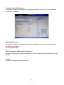
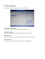
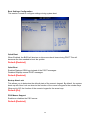
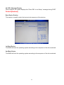
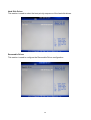
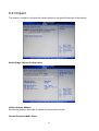
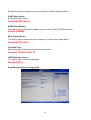
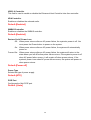
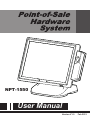
NPT-1550 User Manual Version V1.0 Feb 2012 Copyright 2012 All Rights Reserved Manual Version 1.1 Model Number: NPT-1550 The information contained in this document is subject to change without notice. We make no warranty of any kind with regard to this material, including, but not limited to, the implied warranties of merchantability and fitness for a particular purpose. We shall not be liable for errors contained herein or for incidental or consequential damages in connection with the furnishing, performance, or use of this material. This document contains proprietary information that is protected by copyright. All rights are reserved. No part of this document may be photocopied, reproduced or translated to another language without the prior written consent of the manufacturer. TRADEMARK Intel®, Atom™ brand are registered trademarks of Intel® Corporation. Microsoft® and Windows® are registered trademarks of Microsoft Corporation. Other names and brands may be claimed as the property of others. 1 Safety IMPORTANT SAFETY INSTRUCTIONS 1. To disconnect the machine from the electrical power supply, turn off the power switch and remove the power cord plug from the wall socket. The wall socket must be easily accessible and in close proximity to the machine. 2. Read these instructions carefully. Save these instructions for future reference. 3. Follow all warnings and instructions marked on the product. 4. Do not use this product near water. 5. Do not place this product on an unstable cart, stand, or table. The product may fall, causing serious damage to the product. 6. Slots and openings in the cabinet and the back or bottom are provided for ventilation to ensure reliable operation of the product and to protect it from overheating. These openings must not be blocked or covered. The openings should never be blocked by placing the product on a bed, sofa, rug, or other similar surface. This product should never be placed near or over a radiator or heat register or in a built-in installation unless proper ventilation is provided. 7. This product should be operated from the type of power indicated on the marking label. If you are not sure of the type of power available, consult your dealer or local power company. 8. Do not allow anything to rest on the power cord. Do not locate this product where persons will walk on the cord. 9. Never push objects of any kind into this product through cabinet slots as they may touch dangerous voltage points or short out parts that could result in a fire or electric shock. 10. Never spill liquid of any kind on the product. 2 CE MARK . This device complies with the requirements of the EEC directive 2004/108/EC with regard to “Electromagnetic compatibility” and 2006/95/EC “Low Voltage Directive” This device complies with part 15 of the FCC rules. Operation is subject to the following two conditions: (1) This device may not cause harmful interference. (2) This device must accept any interference received, including interference that may cause undesired operation. CAUTION ON LITHIUM BATTERIES There is a danger of explosion if the battery is replaced incorrectly. Replace only with the same or equivalent type recommended by the manufacturer. Discard used batteries according to the manufacturer’s instructions. LEGISLATION AND WEEE SYMBOL 2002/96/EC Waste Electrical and Electronic Equipment Directive on the treatment, collection, recycling and disposal of electric and electronic devices and their components. The crossed dustbin symbol on the device means that it should not be disposed of with other household wastes at the end of its working life. Instead, the device should be taken to the waste collection centers for activation of the treatment, collection, recycling and disposal procedure. To prevent possible harm to the environment or human health from uncontrolled waste disposal, please separate this from other types of wastes and recycle it responsibly to promote the sustainable reuse of material resources. Household users should contact either the retailer where they purchased this product, or their local government office, for details of where and how they can take this item for environmentally safe recycling. Business users should contact their supplier and check the terms 3 and conditions of the purchase contract. This product should not be mixed with other commercial wastes for disposal. 4 Revision History Changes to the original user manual are listed below: Version Date 1.0 Feb. 2012 Description Initial release 5 Table of Contents 1. Package Checklist……………................................................................ 1-1 1-2 Standard items…………………………………………………………………… Optional items……………………………………………………………………. 2. System View………………………………………………………………... 3. System Assembly & Disassembly……………………………………… 3-1 Replace the HDD…………………………………………………………………... 3-2 Replace the Motherboard…………………………………………………………. 3-3 Replace the Inverter Board & Touch Board…………………………………... 3-4 Install VFD & MSR (Optional)…………………………………........................... 4. Specification……………………………………………………………….. 5. Jumper Settings…………………………………………………………… 1 1 1 2 4 4 5 6 7 8 10 5-1 NP-D5250 Motherboard Layout………………………………………………….. 10 5-2 Connectors Description…………………………………………………………… 5-3 Jumper Settings……………………………………………………………………. 5-4 Install a Cash Drawer……………………………………………………………… 11 12 13 6. BIOS Settings………………………………………………………………. 14 6-1 Entering Setup …………………………………………………………………….. 6-2 The Main Menu…………………………………………………………………….. 6-3 Main Features……………………………………………………………………… 6-4 Advanced Features………………………………………………………………... 6-5 Boot Settings……………………………………………………………………….. 6-6 Chipset……………………………………………………………………………… 6-7 PCIPnP……………………………………………………………………………… 6-8 Security Settings…………………………………………………………………… 6-9 Exit Options………………………………………………………………………… 14 14 15 16 23 27 30 31 32 Appendix…………………………………………………………………………. 34 6 1. Package Checklist 1-1 Standard items a. System b. power adapter 1-2 Optional items a. Second Display b. MSR d. driver bank/e-User Manual c. VFD e. power cord 1 2. System View Front View Rear View No. Description 1 Touch Screen 2 MSR/2-in-1 MSR (Option) 3 Power Button & Power LED 4 Model No. Label & OS License Label 5 Stand 6 Cables outlet 7 Heat sink Side View Top View No. Description 8 VFD (OPTION) 9 System Box (Inside with Motherboard) 10 Vesa Cover 11 Cables outlet 2 Rear I/O View No. Description 1 DC 12V IN 2 Cash Drawer Port 3 USB (x4) 4 LAN (10/100/1000) 5 COM(x4) 6 2nd VGA 7 DC 12V OUT 8 2.5 HDD 9 Parallel port 10 Line OUT 3 3. System Assembly & Disassembly 3-1 Replace the HDD a. Unfasten the screws (x2) to remove the HDD cover. b. Disconnect the HDD Cable and take out the HDD with HDD metal bracket. c. Unfasten c. Unfasten the screws (x4) at both sides of HDD metal bracket. d. Slide out the HDD from the HDD metal bracket and replace the HDD. 4 3-2 Replace the Motherboard To replace the motherboard, please follow the below steps: (1) Disconnect the HDD cable from the motherboard (Chapter 3-1, step a,b) (2) Open the system box to access the motherboard (See below) a. Unfasten the screws(x11) on the back of system box. b. Press the Front bezel then separate top and bottom chassis(L1、L2). c. Remove the LCD rear cover. d. Unfasten the screw(x8) fixing the motherboard and heatsink. e. Unfasten the screw(x4) fixing the motherboard. f. cable unplug out the motherboard with metal I/O bracket. 5 3-3 Replace the Inverter Board & Touch Board: 3-3-1 Replace the Inverter Board a. The location of Inverter board on the LCD sheet metal bracket. b. Unfasten the screws (x2). c. Disconnect the cables (x3). 3-3-2 Replace the Touch Board: a. The location of touch board on the LCD sheet metal bracket. b. Unfasten the screws (x2). c. Disconnect the cables (x2). 6 3-3 Install VFD & MSR (Optional): 3-4-1 VFD install: a. Unfasten the screws. b. Install VFD Module on the rear cover. c. Tighten the screws. 3-4-2 MSR install: a. Unfasten the screws. b. Pull the MSR cover from rear cover. c. Install the MSR Module on the rear cover. d. Tighten the screws. 7 4. Specification Model Name NPT-1550 Motherboard NP-D5250 Processor Intel® Atom D525 Dual-Core Processor, 1.8GHz, 1M L2 Cache Chipset Intel® ICH8M, NH82801HBM I/O Control Hub System Memory 1 x SO-DIMM DDR3 800 2GB Graphic Memory Integrated Intel® Graphics Media Accelerator 3150, share system memory up to 256MB LCD / Touch Panel LCD Size 15” TFT XGA (1024x768) 250cd/m² LCD Panel Touch Screen 15" 5-wire Resistive Touch Panel Tilt Angle 0° ~ 80° Storage Device Hard Drive 1 x 2.5" SATA HDD 160GB 5,400rpm, Removable type Expansion mini-PCIe 1 x mini-Card slot (mini-PCIe / USB) Rear I/O Serial port 4 x RS-232 USB port 4 x USB 2.0 Parallel port 1 x Parallel LAN Port 1 x RJ-45 (10/100/1000Mbps Ethernet) VGA 1 x VGA Cash Drawer Port 1 x RJ-11, support 2 cash drawers (24V, Max 1.1A) DC Jack 1 x 12V-IN DC-OUT Jack 1 x 12V-OUT for 2nd Display Power Line-OUT 1 x Line-OUT for Audio Audio System Buzzer 1 x System Buzzer Internal Speaker 1 x 3W Speaker System Control/ Indicator Power Switch 1 x Power ON/OFF switch Power LED 1 x Power ON LED (Green) Power Power Supply External AC-DC 12V/96W or 100W Power Brick Peripheral (Optional) 8 MSR ISO 3 Tracks MSR (USB or PS/2) Customer Display 2 x 20 VFD customer display 2nd Display 15" LCD monitor Certificate EMC & Safety FCC Class A / CE / LVD Environment Operating Temperature 0°C ~ 40°C (32°F ~ 104°F) Storage Temperature -20°C ~ 60°C (-4°F ~ 140°F) Operating Humidity 20% - 80% RH non-condensing Storage Humidity 20% - 85% RH non-condensing Dimension 80° tilt angle 368(W) x 331(H) x 210(D) mm (No MSR) / 410(W) x 331(H) x 210(D) mm (w/ MSR) Display Head 368(W) x 282(H) x 69.9(D) mm (No MSR) / 410(W) x 282(H) x 69.9(D) mm (w/ MSR) Footprint 249 (W) x 209 (D) mm Package Size 490(L) x 390(W) x 400mm(H) (No MSR) / 530(L) x 390(W) x 400mm(H) (w/ MSR) Weight Net Weight 7.2kg (15.4lbs) Gross Weight 9.5kg (17.8lbs) OS Support Windows POSReady 2009, Win 7 Pro, XP Pro, Win CE 6.0. Linux 2.6 / 2.4 (Ubuntu, SuSE, CENTOS, Fedora) 9 5. Jumper Settings 5-1 NP-D5250 Motherboard Layout 10 5-2 Connectors Description Connector Purpose Connector Purpose CN1 CN3 CN5 CN7 CN9A COM5 COM6 MINI PCI-E Parallel Interface COM3 Connector CN2 CN4 CN6 CN8 CN9B LVDS CON 24bit LVDS CON 18bit AUDIO (Line out and MIC IN) COM4 VGA Connector CN10 COM1A CON1 CON4 DC-Power Input Connector COM1 Connector MSR CONN LAN+USBx2 Connector COM1B CON3 CON5 COM2 Connector DC-Power Output Connector RJ11 Connector J1 J5 J9 J11 J14 INV18 1x5 JST Connector JST USB Connector HW RESET SW SPEAK OUT TOUCH Connector J4 J7 J10 J12 SATA Power Connector JST USB Connector. KB Connector POWER SW JP5 LED Connector 11 5-3 Jumper Settings Panel Power selection:JP1 Function JP1 (1-2) (2-3) JP1 (1-2) (2-3) ◎3V 5V ◎Default setting 1-2 short. CMOS CLEAR SIGNAL: JP2 Function ◎NORMAL CLEAR CMOS ◎Default setting 1-2 short. Note: 12 5-4 Install a Cash Drawer You can install a cash drawer through the cash drawer port. Please verify the pin assignment before installation. Cash Drawer Pin Assignment Pin Signal 1 CASEOPEN2# 2 CASH1_P 3 CASEOPEN# 4 24V 5 CASH2_P 6 GND Cash Drawer Controller Register The Cash Drawer Controller use one I/O addresses to control the Cash Drawer. 13 6. BIOS Settings This chapter explains how to use the BIOS Setup program for the NPT-1550. The current BIOS setup pictures in the chapter are for reference only, which may change by the BIOS modification in the future. User can download any major updated items or reversion from NEXCOM web site http://www.nexcom.com.tw. If any unclear message occurs, please contact NEXCOM customer service representative for help. When the BIOS Main Menu is displayed, the following items can be selected. Use the arrow keys to select items and the Enter key to accept and enter the sub-menu. 6-1 Entering Setup Power on the computer and press <Del> immediately will allow you to enter Setup.The other way to enter Setup is to power on the computer, when the below message appears briefly at the bottom of the screen during the POST (Power On Self Test), press <Del> key. 6-2 The Main Menu Once you enter AMI BIOS CMOS Setup Utility, the Main Menu will appear on the screen. The Main Menu allows you to select from six setup functions and one exit choices. Use arrow keys to select among the items and press <Enter> to accept or enter the sub-menu. ※Note: The BIOS setup menus shown in this section are for reference only and may 14 not exactly match the items of your BIOS version. 6-3 Main Features Use this menu for basic system configuration. 15 6-4 Advanced Features Use this menu to set the Advanced Features available on the system. IDE Configuration This section is used to configure the IDE drives. USB Configuration This section is used to configure USB devices. ACPI Configuration This section is used to configure the Advanced ACPI configuration. MPS Configuration This section is used to configure the MPS configuration. Super IO Configuration This section is used to configure the I/O functions supported by the onboard Super I/O chip. Hardware Health Configuration This section is used to configure the hardware monitoring events such as the temperature, fan speed and voltages. 16 IDE Configuration This section is used to configure the IDE drives. Configure SATA As IDE: This option configures the Serial ATA drives as Parallel ATA physical storage device. Default:[Enhanced] AHCI: This option configures the Serial ATA drives to use AHCI (Advanced Host Controller Interface). AHCI allows the storage driver to enable the advanced Serial ATA features which will increase storage performance. Default: [IDE] 17 USB Configuration This section is used to configure USB devices. Legacy USB Support Due to the limited space of the BIOS ROM, the support for legacy USB keyboard (in DOS mode) is by default set to Enabled. With more BIOS ROM space available, it will be able to support more advanced features as well as provide compatibility to a wide variety of peripheral devices. If a PS/2 keyboard is not available and you need to use a USB keyboard to install Windows (installation is performed in DOS mode) or run any program under DOS, set this field to Enabled. Default: [Enabled] USB 2.0 Controller Mode Sets the USB 2.0 controller mode to HiSpeed (480 Mbps) or FullSpeed (12 Mbps). Default:[HiSpeed] BIOS EHCI Hand-Off Enable this field when using operating systems without the EHCI hand-off support. Default:[Enabled] Hotplug USB FDD support Allows you to enable or disable the support for a USB floppy disk drive. When set to auto, the system automatically detects the device and enables the support for the device. Default: [Auto] 18 ACPI Configuration This section is used to configure the Advanced ACPI configuration. Suspend mode Sets the ACPI Standby State when system goes into ACPI Standby Mode.S1/PSOS: Power on Suspend. In the S1 state, a bit more power is consumed and the fans remain active. S3/STR: Suspend to RAM. Provides the greatest amount of power savings. While in the S3 state, the PC is silent with the monitor and fans off. Default: [S1 (POS)] Repost Video on S3 Resume Set this value to allow video repost support. No: this setting prevents the video BIOS to be initialized when coming out of the S3 state. Yes: this setting allows the video BIOS to be initialized when coming out of the S3 state. ACPI APIC support The ACPI standard (Advanced Configuration and Interface power) allows the operating system directly to check the functions of energy saving and the PnP (Plug and Play) functionality. The ACPI functions are normally activated by the BIOS. The choices are: Enabled and Disabled Default:[Enabled] 19 MPS Configuration This section is used to configure the MPS configuration MPS Revision Selects the MPS revision used by the system. Default:[1.4] Configuration Win627 Super IO Chipset This section is used to configure the I/O functions supported by the onboard Super I/O chip. Parallel Port Address Selects the parallel port’s base address. Default:[378] 20 Parallel Port Mode This field is used to select normal, ECP or EPP mode of the parallel port. Default: [Normal] Parallel Port IRQ This field is used to select an IRQ for the parallel port. Default: [IRQ7] Serial Port1 Address to Serial Port6 Address Auto The system will automatically select an I/O address for the onboard serial port. 3F8/IRQ4, 2F8/IRQ3, 3E8/IRQ4, 2E8/IRQ3 Allows you to manually select an I/O address for the onboard serial port. Disabled Disables the onboard serial port. Default: Serial Port1 Address:[3F8] Serial Port1 IRQ[4] Serial Port1 Voltage select [RI] Serial Port2 Address[2F8] Serial Port2 IRQ[3] Serial Port2 Voltage select[RI] Serial Port3 Address[3E8] Serial Port3 IRQ[5] Serial Port3 Voltage select [RI] Serial Port4 Address[2E8] Serial Port4 IRQ[10] Serial Port4 Voltage select[RI] Serial Port5 Address[4F8] Serial Port5 IRQ[11] Serial Port6 Address[4E8] Serial Port6 IRQ[7] 21 Hardware Health Configuration This section is used to configure the hardware monitoring events such as the temperature, fan speed and voltages. H/W Health Function This section is used to configure the hardware monitoring events such as the temperature, fan speed and voltages. Default:[Enabled] CPU Temperature and System Temperature Detects and displays the current temperature of the CPU and the internal temperature of the system. Vcoreft Detects and displays the output voltages 22 6-5 Boot Settings This section is used to configure settings during system boot. Boot Settings Configuration This section is used to configure settings during system boot. Boot Device Priority This section is used to select the boot priority sequence of the devices. Hard Disk Drives This section is used to select the boot priority sequence of the hard disk drives. Removable Drives This section is used to configure the Removable Drives configuration 23 Boot Settings Configuration This section is used to configure settings during system boot. Quick Boot When Enabled, the BIOS will shorten or skip some check items during POST. This will decrease the time needed to boot the system. Default:[Enabled] Quiet Boot Enabled Displays OEM logo instead of the POST messages. Disabled Displays normal POST messages. Default:[Enabled] Bootup Num-Lock This allows you to determine the default state of the numeric keypad. By default, the system boots up with Num-Lock on wherein the function of the numeric keypad is the number keys. When set to Off, the function of the numeric keypad is the arrow keys. Default:[On] PS/2 Mouse Support Enables or disables the PS/2 mouse Default:[Enabled] 24 Hit ‘DEL’ Message Display When enabled, the system displays the “Press DEL to run Setup” message during POST. Default:[Enabled] Boot Device Priority This section is used to select the boot priority sequence of the devices. 1st Boot Device The BIOS will boot the operating system according to the sequence of the drive selected. 2nd Boot Device The BIOS will boot the operating system according to the sequence of the drive selected. 25 Hard Disk Drives This section is used to select the boot priority sequence of the hard disk drives. Removable Drives This section is used to configure the Removable Drives configuration 26 6-6 Chipset This section is used to configure the system based on the specific features of the chipset. North Bridge Chipset Configuration Initiate Graphic Adapter Selects the graphics controller to use as the primary boot device. Internal Graphics Mode Select 27 Selects the amount of system memory used by the internal graphics device. DVMT Mode Select Selects the DVMT mode. Default:[DVMT Mode] DVMT/Fixed Memory This field is used to select the graphics memory size used by DVMT/Fixed mode. Default:[256MB] Boot Display Device This field is used to select the type of display to use when the system boots. Default:[CRT+LVDS] Flat Panel Type Selects the type of flat panel connected to the system. Default: [1024x768 18bit S] LVDS Backlight control This field is use to control the backlight Default:[100%] South Bridge Chipset Configuration 28 USB 2.0 Controller This field is used to enable or disable the Enhanced Host Controller Inter-face controller. HDA Controller Enables or disables the onboard audio. Default:[Enabled] SMBUS Controller Enables or disables the SMBUS controller. Default:[Enabled] Restore On AC Power Loss Off: When power returns after an AC power failure, the system’s power is off. You must press the Power button to power-on the system. On: When power returns after an AC power failure, the system will automatically power-on. Former-Sts: When power returns after an AC power failure, the system will return to the state where you left off before power failure occurs. If the system’s power is off when AC power failure occurs, it will remain off when power returns. If the system’s power is on when AC power failure occurs, the system will power-on when power returns. Default:[Power off] Power Type Selects the type of power supply. Default:[ATX] PCIE Port Configures the Mini PCIE port. Default :[Auto] 29 6-7 PCIPnP This section is used to configure settings for PCI/PnP device. Plug & Play O/S Yes: Configures Plug and Play (PnP) devices that are not required to boot in a Plug and Play supported operating system. No: The BIOS configures all the devices in the system Default:[No] . IRQ3 to IRQ15 Available The specified IRQ is available for PCI/PnP devices. Reserved The specified IRQ is reserved for Legacy ISA devices. Default: IRQ3,IRQ4,IRQ5,IRQ7,IRQ10,IRQ11[Reserved]。 IRQ9,IRQ14,IRQ15[Available] 30 6-8 Security Settings Change Supervisor Password This field is used to set or change the supervisor password. To set a new password: 1. Select the Change Supervisor Password field then press <Enter>. 2. Type your password in the dialog box then press <Enter>. You are limited to eight letters/numbers. 31 6-9 Exit Options Save Changes and Exit: To save the changes and exit the Setup utility, select this field then press <Enter>. A dialog box will appear. Confirm by selecting OK. You can also press <F10> to save and exit Setup. Discard Changes and Exit: To exit the Setup utility without saving the changes, select this field then press <Enter>. A dialog box will appear. Confirm by selecting OK. You can also press <ESC> to exit without saving the changes. Discard Changes: To discard the changes, select this field then press <Enter>. A dialog box will appear. Confirm by selecting OK to discard all changes made and restore the previously saved settings. You can also press <F7> to discard the changes. Load Optimal Defaults: To load optimal default values from the BIOS ROM, select this field then press <Enter>. A dialog box will appear. Confirm by selecting OK. You can also press <F9> to load optimal default values. Load Failsafe Defaults: 32 To load failsafe default values from the BIOS ROM, select this field then press <Enter>. A dialog box will appear. Confirm by selecting OK. You can also press <F9> to load failsafe default values. 33 Appendix Drivers Installation: The shipping package includes a Driver CD. You can find every individual driver and utility that enables you to install the drivers in the Driver CD. Please insert the Driver CD into the drive and double click on the “index.htm” to pick up the models. You can refer to the drivers installation guide for each driverin the “Driver/Manual List”. 34