1
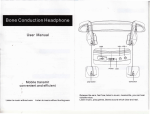
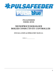
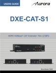
(2) Normal mounting:
Photoelectric triple beam detector User Manual
◆ Detection distance
ABE-50 ABE-100 ABE-150 ABE-200 ABE-250/P VER:ALABE02
1.Parts Description
Model
Detection distance
ABE-50
50m
1.6m
ABE-100
100m
2.0m
ABE-150
150m
2.8m
ABE-200
200m
3.8m
ABE-250/P
250m
5.0m
Beam spread angle
Beam Spread Range
12mm
Mounting height
33mm
33mm
Mounting height
0.7-1.0m
Beam spread
angle
Beam Spread Range
Detection distance
Correction angle
2.Setting Note
Horizontally
180°(±90°)
(1) Do not mount the detectors in following conditions
Vertically
20°(±10°)
3.Setting method
Wall mounting
Wiring Knockout
1)Where installation
base is not stable
2)Where there are blocks
between the receiver and
transmitter
4)Where there are other
infrared detectors working
3)Where sunlight shines
dircctly
1) . Loosen the screw and
remove the cover
2) . Attach the installation
paper to the wall,mark
the holes first and then
make the guide holes.
4) . Drop into the four holes
with the expansion pipes,
fix them with screws.
5) . Connecting wires to the
6) . Review and reset the cover
terminals
( please refer to “beam alignment”)
3) . Wiring hole: Remove the
foam plug,pull wire through.
and reset the foam plug.
5)Do not let the wires in the air
◆ Pole mounting
5 . Connecting wires
Wiring Knockout
(1) Examples
1.Single connect: Control panel operating voltage
DC12V. NC alarm output. Connecting to power
supply parallel (as follows)
Alarm input
Bracket diameter
Control panel
Alarm input
Control panel
1) . Break out the wire
hole and pull out the
wires
2) . Remove the cover
3) . Drop into the holes with
the expansion pipe,fix it
with screws
U type bracket
Transmitter
Receiver
2.Stacked connect. Control panel operating
voltage DC12V.NC alarm output series
connect as follows:
Transmitter
Receiver
3. Series connect;
Control panel operating voltage DC12V. NC alarm output series connect as follows:
4) . Fix the body on the bracket
5) . For the back to back installation
diagram, please refer to the step
5 and 6 of the wall mounting method.
Alarm input
4.Connectors
Control panel
( Warning ): when installation , don’t connect the port with the voltage or current which is
over the normal specification !
Transmitter
Notes: 1 . Power voltage input: DC/AC 12V-24V;
2 . No heater in the package, please order if required.
3 . The tamper switch is independent of other circuit; it
would open if the cover was removed.
Transmitter
(2) The distance between the power and the detector should not be longer than following.
length
12v-24vDC
Transmitter
Receiver
Receiver
Voltage
DC12V
DC24V
Wire diameter
Receiver
12v-24vDC
Notes:
1 . Power voltage input: DC/AC 12V-24V;
2 . No heater in the package, please order if required.
3 .The tamper switch is independent of other circuit;
it would open if the cover was removed.
4 .Relay connection point 1C 24VDC 0.5Amx
0.5mm²(diameter0.8)
400m
2000m
1.75mm²(diameter1.0)
600m
3000m
1.0mm²(diameter1.2)
800m
4000m
1.5mm²(d iameter1.4)
1000m
5000m
8 . Beam frequency
6 . Digital tube voltage indicator
Digital tube indicator (on the right side of PCB shell)
When using some pairs beams or under long-distance applications, select a specific beam
1 .Adjust the beam frequency switch, make sure
the frequency of transmitter must be the
same as frequency of receiver.
frequency to avoid mutual interference between beams.
When using in stack please set the frequency difference of 2,as show below, beams above set to
1,the under one set to 3.2 and 4 frequency setting is the same as 1 and 3.
2 . Adjust the screw and bracket until receiver can
be seen and try to let its position in the line-ofsight center
(1) 2 groups stacked
(2) 6 groups stacked
(3) Perimeter using example 1
3 . Adjust the screw and bracket until receiver
can be seen and try to let its position in the
line-of-sight center.The indication of digital
tube will change between “0 “to”9”.“0”
indicates no signal and alarm output. The
calibration of the optical axis digital tube
indicates “9”.
4 . Operation confirmation.Please make sure
the alarm indicatoris off before testing. If
not please redo the alignment.until the
detector into normal alarm state.
REALIGN
FAIR
Signal strength
GOOD
Transmitter
Receiver
Transmitter
Receiver Receiver
Transmitter Transmitter Receiver
BEST
(5) Perimeter using example 1
(4) 3 groups for long-distance using
7 . DIP switch
DIP switch description (DIP switch at the left side of the main PCB cover, as shown in picture)
Transmitter
Receiver Receiver Transmitter Transmitter
Receiver
Transmitter:
Signal lever Beam power
Transmitter
Beam frequency
(1) 1 and 2 two DIP switches to set the beam frequency,
must be set the same as 1 and 2 two DIP switches’
setting on receiver.
(2) Transmitter operating instructions, set it to off after
debugging and set break code switch to off for saving
energy.
(3) Pre-heating function helps to test heater heating
function, its constant temperature is higher than
heating. If customers buy heaters and use,
keep it in the heating position to save power.
(4) The beam has two level power, please set according
to the needs of the alert distance.
9 . Operation confirmation
Signal Lever
Signal Lever
Alarm
Alarm
Receiver
Receiver
Receiver
Operating
instructions
Respond time
Beam frequency
Alarm Status
(1) 1 and 2 two DIP switches to set the beam frequency,
must be set the same as 1 and 2 two DIP switches’
setting on transmitter.
(2) Transmitter operating instructions, set it to off after
debugging and set break code switch to off for saving
energy.
(3) Pre-heating function helps to test heater heating
function, its constant temperature is higher than
heating. If customers buy heaters and use,
keep it in the heating position to save power.
(4) Interrupt time should be selected according to
actual use.
(5) When interrupted occasionally by birds, leaves or
paper, set longer respond time. And please double
check when finished.
Power on, but indicator
LED does not light (off)
Possible cause
1.DIP switch is in the state of saving
electricity
2.Power cable without voltage;
broken circuit or short circuit;
Transmitter
Please make sure the alarm
indicator is off before testing.
If not, redo the alignment.
Please do the test at the 3 following
positions
1. At the transmitter side
2. At the receiver side
3. In the middle
Alarm indicator turns on when
beam is interrupted, test
finished successfully.
11 . Specifications
10 . Troubleshooting
Symptom
Alarm Status
Remedy
1.Turn on the DIP switch
2.Check power adapter, circuit
and voltage polarity; change
Model
ABE-50
ABE-100
Detecting distance(outdoor)
50m
100m
150m
200m
250m
Detecting distance(indoor)
150m
300m
450m
600m
750m
Detecting distance (Max)
300m
600m
900m
1200m
1500m
ABE-150
ABE-200
Detection method
Simultaneous interruption of 3 infrared beams
Interruption time
50ms,100ms,300ms,700ms(adjustable)
ABE-250/P
adapter or power cable
Number of beams
polarity is incorrect; beyond
3 beams
4(optional,but transmitter should be same with receiver)
Frequency
specified voltage; power cable
Alarm cycle
exceeds the specified length.
2±1s
Tamper
Current consumption (Max)
When beam is blocked,
alarm LED does not
light and alarm
1.There are reflectors or other
transmitters impacting receiver
2.3 beams are not all blocked
transmitters; adjust receiver
2.Ensure 3 beams all blocked
Power and Voltage
IP rating
3.Reduce interruption time
Humidity
4.Alarm output cable is fixed
incorrectly
4.Check receiver terminal and
output cable
Alarm output
Correction angle
Installation location
Weight
When beam is not
blocked, alarm LED
lights and alarm
1.Beam is out of alignment; optical
axis does not overlap
2.There are objects between
receiver and transmitter
3.Frequency is incorrect
4.The cover is dirty or capped
by snow, frost and ice
5.Transmitter dose not output
False alarm
1.Bad wiring and fluctuant power
voltage
2.Movable blocks, like bird, paper,
leaves
3.The installation base is unstable
4.Out of alignment
5.Frequency of transmitter is set “L”
80mA
90mA
100mA
1.Remove reflectors or close other
Operating temperature
3.Setting too long interruption time
NC. Works when cover is removed
70mA
1.Adjust optical axis
2.Check objects between receiver
and transmitter
3.Ensure the frequency of receiver
and transmitter the same
4.Clean cover and use heater
5.Check the power, current and
cable of transmitter
1.Check power, current and wiring
2.Change the installation location
3.Strengthen installation base
4.Adjust optical axis
5.Change Frequency of transmitter
from “L” into “H”
12 . Dimensions
DC12~24V ; AC11-18V
IP 65
-25℃—55℃
95% MAX
Relay output 1C. contact output.DC/AC30V/0.5AMax.
Horizontally 180°; vertically 20°
Indoor/outdoor, wall/pole
1.9KG
110mA