1
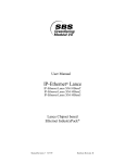
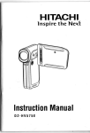
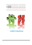
User Manual of 600 series Radio Remote Control
By Alex, Version:201012, China Faryuan, www.ele-b2b.com
Contents
01
Introduction
02
Safety Instruction
04
Definition of model and function introduction
04
600 Series definition
04
Introduction for the transmitter
08
Introduction for the reciever
09
Configuration and instruction
09
The drawing and instruction of the transmiiter `s Configuraton
09
Receiver configuration
10
Wiring diagram
10
600S,600A
10
610S,610A
10
620S,620A
11
System configuration
11
How to set the jumper
12
How to set the transmitting frequency
12
How to set ID codes
14
Frequency and ID codes cross-references
16
Installation Instruction
16
Installation notice
17
Fasten the receiver
18
System test
20
Using Notice
22
Troubleshooting tips
24
System parameter
RADIO
Introduction
600 series wireless remote control system,which is easily used, can be
alone applied in different working condition and industry equipment system, such
as automatic controlling. It can ensure safety requirement of modern industry.
Through many years professional knowledge and technical experience on Industry
communication field, Faryuan keep on develop and make technology first, try to be a
leader of wireless remote control field.
The design of 600 series wireless remote control system, is based on the
maximal safeguard for the user ,and can pass kinds of interfere test of complex
condition .
CE Registration No.: VT09047176
● The major features of radio 600 series are as follow
◆ The system uses advanced microprocessors with highly evolved software
that has redundant error checking and correcting capabilities to ensure 100%
error-free transmission, decoding, and control of all output relays.
◆ The typical character of 600 series wireless remote control system
includes system parts self-diagnosing function.the transmitter has
communication check function and know the situation between transmitter and
receiver( for the detailed , see the manual)
01
◆
02
600 series wireless remote control system, no matter transmitter or
Receiver can be matched according to sepical operation.(for the detailed , see
the manual)
◆ With more than 250 noninterference and different RF channel,it can
guarantee many machines be operated at the same time in the same area.
◆ The Degrees of protection of receiver and transmitter can be above IP65
with good configuration.The transmitter can be used outside completely against
the water come in, as the degrees of protection of water-proof and dust-proof
can be reached IP-66.The receiver is ensure to be used in bad environment as
IP65.
◆ The life of batteries can be used more with lower transmit power.Use 2
pcs“AA” batteries in the trasmitter to make sure at least transmit 100 hours in
the smallest distance.
Safety Instruction
600 series wireless remote control system are relatively simple to use,
however, please read manual before installation,and operate with correct procedure.
It can bring good effect with correct installtion and use
remote control system.
600 series wireless
●
The points should be followed when using
◆ Check the transmitter casing and pushbuttons daily.Should any damage be
found,the unit should be removed from service.
◆ The transmitter voltage should be checked.If the voltage is low(red status
light blinking or completely off),the batteries should be replaced. If the
transmitter is not used for a long time, please take out the batteries and keep it
safe。
◆ The red emergercy stop button should be checked daily to ensure it is in
proper working .If any question, the receiver should be prohitted to use.
◆ Turn the power switch “off” after each use to avoid the mis-operation.
◆ Before starting, please confirm whether the red emergency stop button(EMS)
is turned on.
◆ Do not use the same RF channel and ID code as any other system in use at
the same facility or test at same area.
◆ Never operate a crane or equipment with two transmitters at the same time
with the same RF channel and ID code.
03
Definition of model and function introduction
★ Definition for 600 series
6
**
*
Affixal function
The sort of model
Serial number of design
★ Introduction for functions of transmitter
●
600S: 6X one speed buttons
①
②
③
① Shell
④
⑤
⑥
⑦
⑧
⑨
② Power switch
③ EMS button
④ Down
⑤ Up
⑥ West
⑦ East
⑧ South
⑨ North
04
600A: 6X one-speed buttons+1
switchover buttons+1 interlock button
●
① Shell
①
② Power switch
②
③
④
⑤
⑥
⑦
⑥ West
⑧
⑨
⑧ South
③ EMS button
④ Down
⑤ Up
⑦ East
⑨ North AB AUX ,
Auxiliary Micro-button
A1
A2
A1: AUX Switchover button
A2: Interlock button
610S: 2 two-speed buttons+4 one-speed busttons
●
◆ Attached
drawing and instruction
①
②
③
④
⑤
⑥
⑦
⑧
⑨
① Shell
② Power switch
③ EMS button
④ Down
⑤ Up
⑥ West
⑦ East
⑧ South
⑨ North
05
610A: 2 two-speed buttons + 4 one-speed buttons
+1AUX switchover button+1interlock button
●
◆ Attached
drawing and instruction
①
① Shell
③
②
② Power switch
③ EMS button
④
⑤
⑥
⑦
⑧
⑨
④ Down
⑤ Up
⑥ West
⑦ East
⑧ South
⑨ North AB AUX ,
A1
A2
Auxiliary Micro-button
A1: AUX Switchover button
A2: Interlock button
620S:6 two-speed buttons
●
◆ Attached
drawing and instruction
①
②
③
④
⑤
⑥
⑦
⑧
⑨
① Shell
② Power switch
③ EMS button
④ Down
⑤ Up
⑥ West
⑦ East
⑧ South
⑨ North
06
620A:6 directions, two speed buttons+1
AUX switchover buttons+1 interlock button
●
◆ Attached
drawing and instruction
①
① Shell
②
③
④
⑤
⑥
⑦
⑧
⑨
② Power switch
③ EMS button
④ Down
⑤ Up
⑥ West
⑦ East
⑧ South
⑨ North AB AUX ,
WECAN 600
series
A1
A2
Auxiliary Micro-button
A1: AUX Switchover button
A2: Interlock button
◆ AUX`s funtion: Turn on the power switch, A systems are under control.
The transmitter will control B system if you press AUX button one time. The
transmitter can control two systems at the same time if you press AUX two
times.
Three times , A system will be under control. The same functions as front
intruction.
◆ BK function: BK button can control one relay independently . You can set its
funtion according to your situation.
07
08
★ Introduction for the reciever
①
⑤
⑦
④
⑧
⑥
②
③
Front
① LED Indicator light
Back
② Nameplate
③ Cable
④ The terminal of the controlbox
⑤ Fastness screws1
⑦ Anti-vibration spring
⑥ Fastness screws2
⑧ Installation screw
RADIO
Configuration and instruction
★ Draw of Transmitter `s Configuration Transmitter
1
8
5
6
1、Wireless data module
4
2、IP code dip-switch
2
3、Battery contact
4、Micro-cpu
7
5、Power switch
6、EMS button
7、Double speed button
9
3
8、Indicator light
★ Receiver configuration
2 1
1、Wireless data module
4
4
3
2、Micro-cpu
3、Position for the function
4、Indicator light
7
8
9
5、Wire terminal
6、Relay
5
6
7、 AC power input terminal
8、1A fuse
9、 5A fuse
09
Wiring diagram
★ 600S,600A
★ 610S,610A
★ 620S,620A
Power
Power
Power
Power
Power
Com
Up
Down
Up
Down
Down
East
East
West
West
Com
Com
Up
Up
Com
Power
Com
Main
Main
South
South
North
North
Ground
Ground
Up
Down
Down
East
West
S W
Com
Main
South
North
S N
Ground
Note: please install the yellow-green wire into the equipment shell rightly.
10
System configuration
★ How to set the jumper
The receiver has three function position (details see the picture),you can set
your system function to meet your different requirement, the detailed function
settings as follows:
◆ Special function settings
Join the terminal to the receiver port P3,the relay action for button B is lock
form; on the contrary, the relay action for button B is acted by pressing
◆ Automatic shutoff setting
Join the terminal to the receiver port P2,the main relay will be automatically
breaken after 600s by the receiver, and if no signal for the open, the receiver
won’t answer any command.. on the contrary, the automatic function of the
receiver will be shield
◆ Master-slave setting
Join the terminal to the receiver port P1, then it is master receiver, the
transmitter will control it directly. On the contrary, the receiver is slave receiver,
you will switch to this receiver by “A” button.
◆ You can change the port P1 to make one is master or slave. This function
is only for 600A, 610A and 620A.meanwhile,it is need to instruct whether the
master or slave receiver, the relay “LV” will be closed only for the current
11
12
controlled machine. User can meet the instructions controlled by corresponding
indicator to the relay
Note: please shut off the receiver power first and change the port, then it is
valid to open the receiver.
★ How to set the frequency of the transmitter
Both the transmitter and the receiver, there have a 8 dial-up switch (see
photo), if this address is changed ,the working frequency of the transmitter and the
reciver will also be changed.
Note:
◆ Finishing the setting of dial-up swich, please cut off the power, and then it
will be effective after electricity.
◆ 600 series supply more than 256 channels for your choice, please
choose the allowed channel to operate, we promise most channels is available
and reliable, but not sure every channel, if you find wrong channel, please trip
off to use.
★ How to match ID code
600 series remote controllers have been set corresponding ID code.
Every unit controller have the unique code. For specific needs, we allow to amend
ID code. For the special customers, they can match the emitters and the receivers
by themselves according to specific operation procedure.
●
The following drawing is ID code programming device
This ID code is 8-position binary system code. Every binary system code
match to a unique FR channel and transmitting frequency. ( Please to the Frequency
and ID Code Matching Table). As the drawing shows, “1” is the bottom slot of ID
code. “8” is the top slot. When every positon of the dial up switch direct to the
sign “ON’, it means “0”, Or it means “1”.
ON
1
2
3
4
5
6
7
8
ID code
For example, if you want to set the transmitting frequency to 420MHZ, you will
find the corresponding ID code :00111010”. The ID code programming device will
be like as follows,
ID code is the state of :00111010”.
ON
1
2
3
4
5
6
7
ID code is the state of :00111010”
8
13
14
★ Frequency and ID Code Matching Table
Frequency
Frequency
Frequency
Frequency
Frequency
ID Code
ID Code
ID Code
ID Code
ID Code
(MHZ)
(MHZ)
(MHZ)
(MHZ)
(MHZ)
408.4 00000000 418.8 00110100 429.2 01101000 439.6 10011100
408.6 00000001
419
408.8 00000010 419.2 00110110 429.6 01101010
409
440
10011110 450.4 11010010
430
01101100 440.4 10100000 450.8 11010100
409.4 00000101 419.8 00111001 430.2 01101101 440.6 10100001
409.6 00000110
420
441
10100011 451.4 11010111
431
01110001 441.4 10100101 451.8 11011001
410.4 00001010 420.8 00111110 431.2 01110010 441.6 10100110
410.6 00001011
421
11011010
442
10101000 452.4 11011100
00001101 421.4 01000001 431.8 01110101 442.2 10101001 452.6 11011101
411.2 00001110 421.6 01000010
432
01110110 442.4 10101010 452.8 11011110
411.4 00001111 421.8 01000011 432.2 01110111 442.6 10101011
411.6 00010000
422
453
11011111
01000100 432.4 01111000 442.8 10101100 453.2 11100000
411.8 00010001 422.2 01000101 432.6 01111001
443
10101101 453.4 11100001
00010010 422.4 01000110 432.8 01111010 443.2 10101110 453.6 11100010
412.2 00010011 422.6 01000111
433
01111011 443.4 10101111 453.8 11100011
412.4 00010100 422.8 01001000 433.2 01111100 443.6 10110000
412.6 00010101
423
454
11100100
01001001 433.4 01111101 443.8 10110001 454.2 11100101
412.8 00010110 423.2 01001010 433.6 01111110
444
10110010 454.4 11100110
00010111 423.4 01001011 433.8 01111111 444.2 10110011 454.6 11100111
413.2 00011000 423.6 01001100
434
10000000 444.4 10110100 454.8 11101000
413.4 00011001 423.8 01001101 434.2 10000001 444.6 10110101
413.6 00011010
424
455
11101001
01001110 434.4 10000010 444.8 10110110 455.2 11101010
413.8 00011011 424.2 01001111 434.6 10000011
414
452
00111111 431.4 01110011 441.8 10100111 452.2 11011011
410.8 00001100 421.2 01000000 431.6 01110100
413
11010101
00001000 420.4 00111100 430.8 01110000 441.2 10100100 451.6 11011000
410.2 00001001 420.6 00111101
412
451
00111010 430.4 01101110 440.8 10100010 451.2 11010110
409.8 00000111 420.2 00111011 430.6 01101111
411
11010000
00000011 419.4 00110111 429.8 01101011 440.2 10011111 450.6 11010011
409.2 00000100 419.6 00111000
410
450
00110101 429.4 01101001 439.8 10011101 450.2 11010001
445
10110111 455.4 11101011
00011100 424.4 01010000 434.8 10000100 445.2 10111000 455.6 11101100
414.2 00011101 424.6 01010001
435
10000101 445.4 10111001 455.8 11101101
414.4 00011110 424.8 01010010 435.2 10000110 445.6 10111010
456
11101110
Frequency
Frequency
Frequency
Frequency
Frequency
ID Code
ID Code
ID Code
ID Code
ID Code
(MHZ)
(MHZ)
(MHZ)
(MHZ)
(MHZ)
414.6 00011111
425
01010011 435.4 10000111 445.8 10111011 456.2 11101111
414.8 00100000 425.2 01010100 435.6 10001000
415
446
10011100 456.4 11110000
00100001 425.4 01010101 435.8 10001001 446.2 10111101 456.6 11110001
415.2 00100010 425.6 01010110
436
10001010 446.4 10111110 456.8 11110010
415.4 00100011 425.8 01010111 436.2 10001011 446.6 10111111
415.6 00100100
426
415.8 00100101 426.2 01011001 436.6 10001101
416
447
11000001 457.4 11110101
437
10001111 447.4 11000011 457.8 11110111
416.4 00101000 426.8 01011100 437.2 10010000 447.6 11000100
416.6 00101001
427
458
11111000
01011101 437.4 10010001 447.8 11000101 458.2 11111001
416.8 00101010 427.2 01011110 437.6 10010010
448
11000110 458.4 11111010
00101011 427.4 01011111 437.8 10010011 448.2 11000111 458.6 11111011
417.2 00101100 427.6 01100000
438
10010100 448.4 11001000 458.8 11111100
417.4 00101101 427.8 01100001 438.2 10010101 448.6 11001001
417.6 00101110
428
449
418.2 00110001 428.6 01100101
439
10011001 449.4 11001101
418.4 00110010 428.8 01100110 439.2 10011010 449.6 11001110
429
11111101
11001011 459.4 11111111
00110000 428.4 01100100 438.8 10011000 449.2 11001100
418.6 00110011
459
01100010 438.4 10010110 448.8 11001010 459.2 11111110
417.8 00101111 428.2 01100011 438.6 10010111
418
11110011
00100110 426.4 01011010 436.8 10001110 447.2 11000010 457.6 11110110
416.2 00100111 426.6 01011011
417
457
01011000 436.4 10001100 446.8 11000000 457.2 11110100
01100111 439.4 10011011 449.8 11001111
15
Installation instruction
★ Installation notice
●
Check and confirm the control traveling crane is normal
before installation.
●
Turn off the power.
●
For the receiver position, wherever the crane goes,
it should not impact any building extruded.
●
The receiver should be fixed tightly,
otherwise it maybe loose and dropped.
●
It should learn about the crane power and emitter’s function
settings (include relay output) to avoid incorrect connection.
●
The receiver position should be away from motor, transducer
and cable at least 3 meters, (see following picture) to avoid
unnecessary interference.
Receiver
>3M
Motor
>3M
>3M
Transducer
M
Cable
16
●
The receiver should be at the top of the electricity box and then
take the output cable into the electricity box, don’t fix the
receiver inside the box. If must be inside the box, then please
install the Antenna outside the box.
Receiver
Receiver
Babl e
Ele. box
Ele. box
★ Fasten the receiver
●
Please install the receiver properly to avoid the shake
③ Nut
① Screw 1
④ Screw 2
② Shockproof spring
⑤ Installation screw
17
18
Installation of the shockproof spring
★ System test
Notice:
● please sure that all wiring is right and under good protection, all
screws are tight, fix the cable between the reciever and the crane to
avoid the cable be short by the crane shake. Then open the crane
power supply.
● Please read the manual before installation and usage.
● Please close the main power when you install and maintain the
remote control to avoid touch electricity.
The transmitter is lay at safety place, nobody can push the button to
avoid accident happen.
Controlable crane should has mainpower relay, limit switch and other
safety facilities.
● Please stop using when there is lightning strike or disturbance.
Non-training person don’t open the machine to avoid break it.
This manual is for user reference, please contact us for details.
We hold the right to amend the machine and manual without notice,
operation manual is not confirmed to the machine, please enquiry
our company.
●
Test process
◆ First loosen the EMS button,method: rotate the button 1/4 circle clockwise,
it will bounce automatic. Then rotate the left rotory switch to “ON” position, the
center indicator will be red, later turn to blue.
Note 1: when you press the EMS button, you must redo the above operation to
open the receiver.(loosen the EMS, and rotate the switch to ON position)
Note 2: don’t press any button of the transmitter during the power on, or it will
make the transmitter into protection.(not sending any signal)
Note 3: after the power on, the transmitter appear red 3 seconds, then turn to
blue, or sparkle one time on red then one time on blue, etc two different condition,
details see the manual.
◆ Under default state, the control relay of the receiver will disconnect after
10minutes starting from not any signal. If you don’t need this function, I give a
suggestion for you: move the relevant connecting pieces, then the control relay
keep contact until receiving the EMS signal. Details operation see the manual.
◆ Make sure that the contactor is off after pressing the EMS button.
◆ Test each function of the relay to meet your requirement.
◆ Operate the emitter farthest to check the signal. If the crane action is
discotinuous or blind, then the operation is very dangerous.
◆ Note: whenever keep your emitter and leave it at proper place. Make sure no
one can operate it, or it will cause very serious aftereffect.
19
20
Using Notice
●
Install the alkalic battery rightly, suggest to use above 1600AH
battery to make the use time reach 100hours. Don’t use NIH
battery, its voltage is only 1.2V.
●
Make sure the Red EMS button is loose and then turn the emitter
power button to ON.
●
Please pay attention to observe the indicator, it will help you to
use the remote system.
◆ The explication between the indicator of the transmitter and the
corresponding status
LED status
Complement
Explication
Processing method
Red light blink then
close
And then operate
normal(blue light is
bright)
The transmitter is
normal, the voltage &
buttons are normal,
communication good
Operation normal
And then red blink one
time after pressing any
buttons
The transmitter is
low voltage, please
change
the battery on time.
Please open the
machine after change
the battery.
And then no action
after pressing any
buttons
There is any button
in touch status, the
transmitter
pretect itself.
Please check the
buttons blocked or
depressed and then
open the machine.
Red light light 3s then
warning
Weak signal,please
And then normal
ensure that there is no
Weak signal, please
operation(blue light is shielding or interferent
attention to use.
between the transmitter
bright)
and the receiver.
●
Every time you press EMS button,the emitter will send stop signal
to the receiver continously, the signal keeps 3 seconds then stop
sending, you must press EMS button to continue. If you turn the
power to “OFF”, then the EMS is invalid.
●
Before close the power of the emitter, please press the red EMS
button, then turn the power button to “OFF”. Don’t close the
power directly, it won’t disconnect the relay and keeping on.
●
Button interlock: the emitter has the function, when you press
“UP” button, then the emitter won’t respond “DOWN”
command.
●
Change the battery: please change the battery on time when the
voltage is low, you can open the battery cover, take out them and
put new battery.
◆ The explication between the indicator of the transmitter and the
corresponding status
LED status
Complement
Explication
AC indicatoris bright
Voltage normal
Sin indicatoris bright
Normal signal
receiving
M blue lightis bright
The receiver is open,
MAIN relay close
M red lightis bright
The receiver is in 2
speed status.
A indicator is bright
U,D,E,W,N,S is bright
Remark
The receiver AUX relay
600A,610A,620Ahave
close
Corresponding
direction relay acts
21
22
Troubleshooting tips
◆ If the remote control is not working, please remove the failure according the
following explain.
◆ When the controller can’t work normally (pressing the emitter buttons, the
receiver has not action), please check the failure by the following steps:
Item
Failure description
Method
◆ Confirm if the battery power is normal.
a. Check the battery directions
Emitter LED light doesn’t
1
b. Check the battery box directions
shine, Receiver has no
action.
c. Check the battery capacity
d. Check if the tube is break or uncertain close
◆ send to repair
◆ Confirm the receiver power input is normal.
◆ Check if AC power fuses and DC power fuse
Emitter LED light is normal,
2
but Receiver has not
action.
melt, if it is necessary, turn off the power and use
the spare fuse.
◆ Confirm if the relay output fuse melt, if it is
necessary, please use the spare fuse.
◆ Send to repair.
Item
Failure description
Method
◆ Confirm if the relay output fuse melt, if it is
necessary, please use the spare fuse
3
Some actions is not
working
◆ Comfirm if original cable control system
works, if so, find the factory to repair.
◆ Send to repair.
◆ Confirm the emitter battery is abundance
◆ Confirm the receiver doesn’t shield by
corresponding metal cover or net.
4
The Controller Distance
become near
◆ Confirm surround has not be interfered by
strong wireless.
◆ Confirm no same frequency interfered, which
can use to change the channel.
◆ Send to repair.
23
24
system parameter
●
600 new double speed series
●
Constant technique parameter
Receiver
600S
600S
600A
620S
620A
Work voltage
DC12V,DC24V,AC85-400V
Connection mode
Pin insert terminal block
Relay capacity
10A 250V
Respond time
<100ms
Use temperature
-20-70℃
Antenna
outside
Defend grade
IP66
The emitter
Model
600S
600A
620S
620A
Buttons
6
6+1
6
6+1
Selection key
0
1
0
1
Shell
ABS enhanced plastics
Buttons mode
High reliability two step button
Antenna
Inside or outside
Battery
2pcs AA battery
Battery life
Continous signal sending more than 100hours
Frequency
400-460MHz
Power
< 10mW
Modulation
frequencies
Frequency modulation
Range
Industry condition 100m
Defend grade
IP66
Notice: the environment is bad or distance more than 100m, please add the antenna.