1
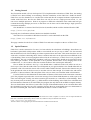
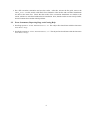
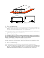
VTT Technical Research Centre of Finland
FDS+Evac – User’s Guide
(FDS 4.06, Evac 1.00b)
Timo Korhonen and Simo Hostikka
VTT Technical Research Centre of Finland
P.O. Box 1000
FI-02044 VTT, Finland
25th August 2006
Disclaimer
VTT Technical Research Centre of Finland makes no warranty, expressed or implied, to users of
FDS+Evac, and accepts no responsibility for its use.
The mention of computer hardware or commercial software does not constitute endorsement by VTT
Technical Research Centre of Finland, nor does it indicate that the products are necessarily those best suited
for the intended purpose.
2
Contents
1 Introduction
1.1 Getting Started . . . . . . . . . . . . . . . . . . . . . . . . . . . . . . . . . . . . . . . . .
1.2 Special Features . . . . . . . . . . . . . . . . . . . . . . . . . . . . . . . . . . . . . . . . .
4
5
5
2 Running FDS+Evac
2.1 Updating an Existing FDS Input File to a FDS+Evac Input File . . . . . . . . . . . . . . . .
2.2 Error Statements, Reporting Bugs, and Getting Help . . . . . . . . . . . . . . . . . . . . . .
6
6
8
3 Setting up the Input File for FDS+Evac
3.1 The Numerical Evacuation Grids . .
3.2 The TIME Namelist Group . . . . .
3.3 The SURF Namelist Group . . . . .
3.4 The MISC Namelist Group . . . . .
3.5 The VENT Namelist Group . . . . .
3.6 The HOLE Namelist Group . . . . .
3.7 The OBST Namelist Group . . . . .
3.8 The PERS Namelist Group . . . . .
3.9 The EVAC Namelist Group . . . . .
3.10 The EVHO Namelist Group . . . . .
3.11 The EXIT Namelist Group . . . . .
3.12 The ENTR Namelist Group . . . . .
3.13 The DOOR Namelist Group . . . . .
3.14 The CORR Namelist Group . . . . .
.
.
.
.
.
.
.
.
.
.
.
.
.
.
.
.
.
.
.
.
.
.
.
.
.
.
.
.
.
.
.
.
.
.
.
.
.
.
.
.
.
.
.
.
.
.
.
.
.
.
.
.
.
.
.
.
.
.
.
.
.
.
.
.
.
.
.
.
.
.
.
.
.
.
.
.
.
.
.
.
.
.
.
.
.
.
.
.
.
.
.
.
.
.
.
.
.
.
.
.
.
.
.
.
.
.
.
.
.
.
.
.
.
.
.
.
.
.
.
.
.
.
.
.
.
.
.
.
.
.
.
.
.
.
.
.
.
.
.
.
.
.
.
.
.
.
.
.
.
.
.
.
.
.
.
.
.
.
.
.
.
.
.
.
.
.
.
.
.
.
.
.
.
.
.
.
.
.
.
.
.
.
.
.
.
.
.
.
.
.
.
.
.
.
.
.
.
.
.
.
.
.
.
.
.
.
.
.
.
.
.
.
.
.
.
.
.
.
.
.
.
.
.
.
.
.
.
.
.
.
.
.
.
.
.
.
.
.
.
.
.
.
.
.
.
.
.
.
.
.
.
.
.
.
.
.
.
.
.
.
.
.
.
.
.
.
.
.
.
.
.
.
.
.
.
.
.
.
.
.
.
.
.
.
.
.
.
.
.
.
.
.
.
.
.
.
.
.
.
.
.
.
.
.
.
.
.
.
.
.
.
.
.
.
.
.
.
.
.
.
.
.
.
.
.
.
.
.
.
.
.
.
.
.
.
.
.
.
.
.
.
.
.
.
.
.
.
.
.
.
.
.
.
.
.
.
.
.
.
.
.
.
.
.
.
.
.
.
.
.
.
.
.
.
.
.
.
.
.
.
.
.
.
.
.
.
.
.
.
.
.
.
.
.
.
.
.
.
.
.
.
.
.
.
.
.
.
.
.
.
.
.
.
.
.
.
.
.
.
.
9
10
11
11
11
12
12
13
13
14
14
15
15
16
16
4 Additional FDS+Evac Input Files
17
5 FDS+Evac: Output Files
17
6 Sample Calculation
18
7 Conclusion
27
References
28
Acknowledgements
29
3
1
Introduction
This document describes, how one does an egress calculation by using the Fire Dynamics Simulator (FDS)
developed at National Institute of Standards and Technology (NIST) and the evacuation module [1] developed at VTT Technical Research Centre of Finland. This combined fire and evacuation simulation program
is called as FDS+Evac in this document. The basic algorithm behind the egress movement is to follow each
person by an equation motion, i.e., do some kind of an artificial molecular dynamics for humans. The forces
acting on humans are both physical forces, like contact forces and gravity, and psycholigical forces exerted
by the environment and other humans. This approach allows each person to have its own personal properties
and escape strategies, i.e., persons are treated as ’agents’. The model behind the movement algorithm is the
social force model introduced by Helbing [2, 3, 4, 5] and its implementation as a module of FDS is described
in the FDS+Evac Technical Reference Guide.
The default values of the parameters of the evacuation calculation are given in the FDS+Evac Technical
Reference Guide. Humans are modeled as circles moving in a 2D geometry. This is just an approximation
of the elliptical shape of the human body, see Figure 1. The body dimensions, d, the unimpeded moving
speeds, v0 , and the relaxation time constant, τ , of typical human population types are shown in Table 1.
These values are drawn randomly for each generated human from uniform distributions, whose width is
given as [d−∆d, d+∆d], etc. The averare diameters and moving speed distributions are taken to be same as
in the Simulex program [6, 7, 8, 9].
Table 1: The default properties of the pre-defined human types ’adult’, ’male’, ’female’, ’child’, and ’elderly’. The last line contains the default parameters of humans if no pre-defined human type is specified on
the human input (EVAC namelist) group.
Human type
Adult
Male
Female
Child
Elderly
Default
d
(m)
0.51
0.54
0.48
0.42
0.50
0.51
∆d
(m)
0.07
0.04
0.04
0.03
0.04
0.00
v0
(m/s)
1.25
1.35
1.15
0.90
0.80
1.25
∆v0
(m/s)
0.30
0.20
0.20
0.30
0.30
0.00
τ
(s)
1.00
1.00
1.00
1.00
1.00
1.00
∆τ
(s)
0.20
0.20
0.20
0.20
0.20
0.20
Figure 1: The true shape of the human body (blue ellipse) is approximated as a circle (red circle) in
FDS+Evac. In the Simulex model the elliptical shape is approximated by three spheres (black circles).
4
1.1
Getting Started
The Evacuation module (+Evac) developed at VTT is implemented as subrutines of FDS. Thus, the running
of FDS+Evac is done similarly as an ordinayry FDS fire simulation, see the FDS User’s Guide for details.
FDS+Evac uses also Smokeview to visualize the results and also the computer hardware requirements are
similar with FDS. Note, that for now FDS+Evac can only be run on a single processor mode, i.e., one
can not use multiple processors. Work is in progress to enable the calculation of the smoke and toxic gas
consentration using multiple processors so that these can be later read in when doing a single processor
evacuation calculation.
One should have a version of the FDS (Version 4) installed, which could be obtained from the URL
http://fire.nist.gov/fds
Especially the visualization software Smokeview should be installed.
The FDS+Evac executable for Windows-based PCs1 can be obtained from the URL
http://www.vtt.fi/fdsevac
This page contains also the User’s Guide of FDS+Evac and some examples on the use of FDS+Evac.
1.2
Special Features
FDS+Evac is under construction. For now, it is best suited to do calculations of buildings, whose floors are
horizontal. Sports halls with spectator stands or concert halls are not yet easy to define. It is also assumed
that the different levels of the building are almost separated from each other. This means that there are not
wide stairs or inclines connecting them. Narrow corridors and stairs can be placed between different levels
of the building. There are no merging flows allowed in the exit stairways, so FDS+Evac is not yet good for
tall buildings. The exit corridor/stairs algorithm is still very simple and it should not be trusted too much
if the stairs get crowded. At this point this is not a problem, because there are no merging flows in the
corridor/stairs, i.e., the exit door at the floor restricts the flow to the corridor quite efficiently.
How to define an exit door? See Fig. 2. One should make a small hole in the wall, where an exit (or a
door) is put. Note, that the width of the exit will depend on your grid resolution. One should define the XB
parameter of the exit such wide, that it will cover the whole width of the hole. Because the obstacles are put
in the grid but the exits (or doors) are not, be sure that exits are wide enough. (Use Smokeview and activate
grid lines.) It does not matter if the end points of the exits (or doors) are somewhat inside solid obstacles.
For now, FDS+Evac has limitations on the number of humans, which can be in the same main evacuation
grid. The program stops and writes out an error message if more than 10000 humans are tried to put to the
same evacuation grid. Usually, one main evacuation grid extends over a whole floor of the building. There
may be many main evacuation grids, e.g., different floors of the building, in the FDS+Evac calculation and
the total number of humans is not restricted by the program, the only limit is the available computer memory.
The user should know that if there is more than a couple of thousands humans on an evacuation floor then
the calculation is going to be very CPU expensive, because there are some double loops over the humans on
the same evacuation grid. This will be remedied in the future versions of FDS+Evac.
1
Some Windows PC users may want to just install Smokeview on their computers in order to view the output of FDS and
FDS+Evac calculations performed by others. In this case, Smokeview may be obtained at the web site
http://fire.nist.gov/smokeview
This site contains a set-up program just for the Windows PC installation of Smokeview.
5
Outflow
VENT
Human − Wall
Forces
Evacuation
HOLE
EXIT
or
DOOR
Figure 2: How to make an exit or a door.
2 Running FDS+Evac
Running FDS+Evac is similar to running FDS, i.e., relatively simple. All of the parameters that describe a
given fire and egress scenario are typed into a text file that will be referred to as the “data” or “input” file.
In this document, the data file will be designated as CHID.data. In practice, the user chooses the ID string
“CHID” so that all of the files associated with a given calculation all have a common prefix.
In Section 6, an example data file will be presented. Several other example files exists at the FDS+Evac
web site http://www.vtt.fi/fdsevac. It is suggested that a new user start with an existing data file,
run it as is, and then make the appropriate changes to the input file for the desired scenario. By running a
sample case, the user will become familiar with the procedure, learn how to examine the results, and ensure
that his/her computer is up to the task before embarking on learning how to create new input files.
The FDS+Evac executable is a single CPU executable (fds406evac100b.exe), which works like the
FDS4 single processor executable. Assuming that an input file called CHID.data exists in some directory,
the user must run the program in a DOS command shell as follows:
Open up a Command Prompt window, and change directories to where the data file for the case is, then run
the code by typing
fds406evac100b.exe < CHID.data
to begin a run, which will output some text on the Command Prompt window. If the user wants to save the
text output going on the Command Prompt window, he/she should type
fds406evac100b.exe < CHID.data 2&>1 > CHID.txt
to begin a run.
2.1
Updating an Existing FDS Input File to a FDS+Evac Input File
• Make a FDS fire input file for your project and do the fire/smoke spread calculations as usual.
• Save the fire input file to some other name (and change also the CHID on the HEAD namelist group).
6
• Put a keyword EVACUATION=.FALSE. to every HOLE line, which you fire input has. Make a copy
of each HOLE line and change EVACUATION value to .TRUE.
• Define &SURF ID=’OUTFLOW’, VEL = +0.00001, TAU_V=0.1 /
• Define grids for the evacuation. Each floor should have its own grid. The z co-ordinate for these grids
should be at a level, where the most obstacles for the movement are, usually about one meter above
the floor.
• Put T=0.0 on the TIME namelist group, comment out the fire grids, and run FDS+Evac. Use Smokeview to see, if the 2D geometry is looking right. You can play around with the ZBAR0 and ZBAR to
take the evacuation layout at a different height.
• Define additional obstacles with EVACUATION=.TRUE., where you do not want humans walking.
• Make additional holes with EVACUATION=.TRUE., where they are needed. Usually these are
needed at exits or doors. See Fig. 2.
• Run FDS+Evac (T=0.0) and see if the 2D geometry is looking correct. If not, correct it by adding
OBST and HOLEs.
• Define evacuation flow field vents (EVACUATION=.TRUE.) that suck fluid out of the evacuation
grids at the places where you want humans to go. These vents should be placed at the doors and exits.
If you are using multiple human flow fields on a floor then you should also specify the MESH_ID on
the VENT lines. This specifies the evacuation grid, where this vent is put. Same applies to holes and
obstacles as well, but usually one can use same obstacles and holes on each flow field.
• Remove CHID_evac.eff file if it exists. Run a short simulation, i.e., put T=1.0. Check the
human flow fields by using Smokeview. Check also that your evacuation geometry looks fine. If not,
add obstacles or holes to the evacuation calculation. Remember to define slice output files at your
evacuation grid locations, e.g.,
&SLCF PBZ=x.x, QUANTITY=’VELOCITY’,VECTOR=.TRUE./
• Define your person classes, the PERS namelists.
• Define your doors, exits, corridors, and entries, the DOOR, EXIT, CORR, and ENTR namelists.
• Place the humans inside the building, the EVAC namelists. Use EVHOs if needed. Note, that humans
should not be placed behind the exits or doors. This might happen accidentally, because humans are
placed randomly to the rectangle, which is given by the XB keyword.
• Once again, run a short simulation, i.e., put the simulation time, e.g., equal to 1.0 s. See, that your
humans have correct initial positions. Edit the initialization file of Smokeview (smokeview.ini) to
make the squares that represent humans larger by changing the value of PARTPOINTSIZE. Note,
that now you had the file CHID_evac.eff on your disk so this file was read in, i.e., the human flow
fields were not recalculated.
• Run a longer simulation and see that the humans are moving correctly, i.e., they are following correct
flow fields and the exits, corridors, and doors are working correctly. Note that the pre-evacuation time
distributions given on the PERS lines should be shorter than the simulation time to see some human
movement.
7
• Do a full evacuation calculation and save the results. After this, activate the fire grids, remove the
CHID_evac.eff file, and do a full FDS+Evac simulation. Now the fire and evacuation simulations
are done at the same time. Check that the results of the evacuation simulations are similar to the
results, which were calculated without the fire simulation. Note, that the results are not exactly similar,
because humans have random initial positions.
2.2
Error Statements, Reporting Bugs, and Getting Help
• Send bug reports to: [email protected]. The subject line should start with the characters
FDS+Evac Bug:.
• Send help requests to: [email protected]. The subject line should start with the characters
FDS+Evac Help:.
8
3 Setting up the Input File for FDS+Evac
This section is a short manual to the FDS+Evac program. Read first the FDS manual, because here only
those features and keywords are presented, which differ from the ordinary FDS fire input. The optional
keywords are presented with a slanted typewriter font, like GAMMA, and the normal keywords with upright
typewriter font, like XBAR. One can use the optional keywords to override the default values of different
parameters.
Note, that the FDS+Evac is still under construction. Read the ’Readme.txt’ file at the source code
directory for additional (quite technical) information. See and read through the example FDS+Evac input
files. These files contain many comment lines, which explain all the major features of the FDS+Evac input
file format and how to do a FDS+Evac simulation. Some general notes on FDS+Evac and some special
features and warnings are listed below:
• New grids must be defined for the evacuation calculation part. These grids are not related to the fire
calculation grids, i.e., their dx and dy may be different and the spatial extent of the grids may also
be different. Usually one defines one main evacuation grid per one floor of the building, if the spaces
on this floor are connected. If there are more than one evacuation zone on a floor then different grids
may be used, but these grids should not be overlapping.
• The evacuation input should be matched to the evacuation floor grid definition. Check the actual
locations of the obstacles using Smokeview. The evacuation related input (namelists DOOR, EXIT,
ENTR, and EVAC) is not moved to the closest grid points. For now, Smokeview do not show these
evacuation related objects.
• In the evacuation grids all obstacles are thick, i.e., they fill at least one grid cell in each direction (x
and y). This is forced in the code (THICKEN_OBSTRUCTIONS=.TRUE. for the evacuation grids).
• The evacuation grids are two dimensional, i.e., they should have KBAR=1.
• The present version of FDS+Evac places the different evacuation objects to the different evacuation
grids according to their x, y, z co-ordinates. One object should belong only to one main evacuation
grid, thus, the main evacuation grids should not be overlapping. Do not place the evacuation objects,
like exits and doors, at the boundaries of the grids, where two grids are touching each other, because
this is ambiguous.
• There are many keywords, which might be given in the FDS+Evac input file and these are also read
in, but the values are not used yet. So this manual only contains keywords, which actually have
some effect on the calculation. (If one looks the evac.f source file, one finds a quite many non-used
keywords.)
• The positions of doors and exits are not checked, i.e., the user should give VENTs and OBSTs so that
in the final FDS+Evac calculation geometry there is an evacuation VENT or empty space behind an
EXIT or a DOOR. See the FDS+Evac Technical Reference Guide how the evacuation flow fields are
defined and used to guide human movement.
• It is good idea to put an exit or a door a little bit inside a hole in the wall, see Fig. 2. This makes the
door flow better, because the door posts will exert forces on humans and humans are removed when
they cross the exit/door line. When a human is removed, the other humans do not anymore feel any
forces from that human. If an exit/door would be on the same level as the wall, then the exit/door
would correspond to a hole in the wall, where humans are jumping down to the street, i.e., the exit
would be a very efficient one (but unsafe...).
9
• Check your EVAC lines that you are not putting humans in areas, where humans should not be. For
example, humans should not be put behind doors or exits. Check also that humans can not go ’out of
bounds’, i.e., that there are no openings in the evacuation geometry where no door or exit is defined.
• Check your EVAC lines that you are not trying to put too many humans on a too small area. Humans
are treated as circles, whose diameters are given as an input. Typical human diameter is somewhere
between 0.5-0.6 m, so you can not put more than two and a half person to a square meter. If you are
trying to populate the floor more dense, the program will stop after the initialization phase and report
an error. User can use Smokeview to see the initial positions of those humans who were positioned
succesfully. Those humans where the error ocurred, i.e. which were the first ones of each EVAC line
that failled to find some empty space, are shown with yellow.
For now, it is better just do a separate evacuation calculation after (or before) the fire calculation if
you do not use smoke and/or FED, i.e., the consentration of the gases CO, CO2 , and O2 , affecting the
calculation. Doing them at the same time might be a little bit tricky, especially when the fire geometry input
and fire grids are not coinciding with the evacuation grid points. (I.e., dx and dy should be nice numbers
and also the co-ordinates of OBSTs, VENTs, etc. should be matched to the grid points.)
3.1
The Numerical Evacuation Grids
The fire and evacuation grids are separate ones. One can do only a fire calculation, only an evacuation
calculation, or both at the same time. The calculation mode is chosen by activating the grids or deactivating
them, i.e., commenting the corresponding &GRID and &PDIM lines out.
Evacuation grid lines have a keyword EVACUATION=.TRUE. on the &GRID line. The default in FDS
fire calculation is .FALSE., i.e., the fire grids do not need the keyword EVACUATION. This is true also
more generally, i.e., one can always run a fire simulation (using the fds4.exe executable) even if there exists
evacuation input in the input file. The FDS4 fire calculation ignores all evacuation lines and keywords.
Main evacuation grids have also a keyword EVAC_HUMANS=.TRUE., which says that this grid will
contain humans. For now, the main evacuation grids should not overlap. Usually, one main evacuation grid
represents a ’floor’. You need more main evacuation grids on a floor if there exists separate parts of the floor,
where the humans are not going to be using same exit routes. In principle, you could manage by one main
grid, but the calculation is faster if you define different grids for the parts, which do not interact with each
other. Future versions of FDS+Evac may have overlapping evacuation grids, which will be a useful feature,
if the building geometry is complex.
All evacuation grids should have a name, i.e., a keyword ID=’NameOfTheGrid’ should be given
on the GRID line. The name of the grid should not be too long, max 26 characters. Of course, the names
of different grids can not be the same. The ID is used later to specify the grid, where some additional
evacuation objects are placed.
Evacuation grids should have KBAR=1, i.e., they are two-dimensional horizontal grids, see Figure 3.
Choose IBAR, JBAR, XBAR0, XBAR, YBAR0, and YBAR so that the dx and dy are nice round numbers, which will fit nicely to your geometry. FDS+Evac does not move the evacuation objects to the closest
grid points (yet, this will change in later versions). Also you should give the positions of all evacuation
objects as multiple of dx and dy. This is not obligatory but one makes less mistakes this way.
Evacuation grids, which are only used to calculate (additional) human movement flow fields should
have EVAC_HUMANS=.FALSE. or just no EVAC_HUMANS keyword at all. False is the default. These
grids should also have names, i.e., the keyword ID=’NameOfTheGrid’. Note, that these grids should
have exactly the same IBAR, JBAR, XBAR0, XBAR, YBAR0, YBAR, ZBAR0, and ZBAR as the
main evacuation grid. This is not checked so the user should do the check.
10
Figure 3: A 2D evacuation grid.
3.2
The TIME Namelist Group
EVAC_DT_FLOWFIELD is the time step for the calculation of the flow fields for human movement. These
fields are calculated before the fire and evacuation calculation, i.e., time has negative values. The
actual fire and evacuation calculation starts at t = 0.0 s. (Default is 0.01 s.)
EVAC_DT_STEADY_STATE is the maximum time step for the human movement, this should not be too
large, should not be larger than 0.1 s. (Default is 0.05 s.)
3.3
The SURF Namelist Group
One should always define a new surface type for the evacuation calculation, which is used to construct the
flow fields that guide the humans to the doors (or to other targets), see Figure 4 and the FDS+Evac Technical
Reference Guide for details. The following line should be given on the input file:
&SURF ID = ’OUTFLOW’, VEL = +0.00001, TAU_V=0.1 /
Note, that VEL should be a really small number, otherwise one might not get a nice potential flow solution.
3.4
The MISC Namelist Group
EVAC_SURF_DEFAULT is the surface default for the evacuation grids. The default is INERT.
EVAC_PRESSURE_ITERATIONS is the number of Poisson solver iterations at each human flow field
time step. If you human flow fields do not look nice, you might need to increase this. Too large
number makes the human flow field calculation to take too much CPU time. (Default is 50.)
11
Figure 4: A 2D flow field used to guide humans to the doors/exits. In this case, only the left exit has an
“outflow” vent, i.e., this fictitious human flow field is used to find the left exit only.
EVAC_TIME_ITERATIONS is the number of human flow field calculation time steps. One should have
a nice converged human flow field, so some iterations are needed. Too large number means too long
CPU time. (Default is 50.)
The flow fields, which are used to guide humans out of the building or to some other targets, are calculated before the actual fire and evacuation simulation, i.e., flow field calculation has t < 0. The product
tflow = EVAC_TIME_ITERATIONS × EVAC_DT_FLOWFIELD defines the duration of the evacuation
flow field calculation. The fields should become ’steady-state’ during this time. Note, that the ramp up time
of the boundary conditions TAU_V=0.1 given on the &SURF ID=’OUTFLOW’ line should be well below
the duration of the flow field calculation tflow . Default tflow is 50 × 0.01 s = 0.5 s.
3.5
The VENT Namelist Group
Because one needs to specify special VENTs for the evacuation calculation, the VENT namelist group has an
additional logical item EVACUATION. If it is .TRUE. then this VENT is omitted in the fire calculation. By
default, the value is .FALSE. The item MESH_ID should also be given, if the VENT is not needed in all
evacuation flow field calculations on this floor. If an evacuation VENT is needed only in some human flow
fields, then a separate VENT line is needed for each of these fields. Note, that an evacuation VENT without
MESH_ID is put on every evacuation flow field on this floor. This means that it is better always to have the
item MESH_ID specified, if EVACUATION=.TRUE. is given.
3.6
The HOLE Namelist Group
This is similar to the VENT namelist group. Only difference is that the HOLE lines should be duplicated,
once with an item EVACUATION=.FALSE. and once with EVACUATION=.TRUE. If the evacuation flow
fields need different holes for different fields, then the item MESH_ID should be given for the evacuation
calculation holes. Holes are treated in the FDS input a little bit different than the obstacles, i.e., first all
obstacles are read in and after this the holes are created. This is true for all meshes, so the evacuation meshes
can mix holes and obstacles incorrectly, if there are no EVACUATION=.FALSE. on the fire calculation
holes.
12
If you have aan ordinary FDS4 input file and want to use this as a starting point of a FDS+Evac input
file, you should add EVACUATION=.FALSE. keyword to every HOLE line, which you have in the FDS4
fire input. After this, you should duplicate these hole lines and change the kewyword EVACUATION value
to .TRUE. if you want the same holes to appear correctly in the evacuation geometry.
3.7
The OBST Namelist Group
This is similar to the VENT namelist group. If the evacuation flow fields need different obstacles for different
human flow fields, then the item MESH_ID should be given for the evacuation obstacles. Usually these
additional evacuation obstacles are introduced at places, where humans are not allowed to walk.
3.8
The PERS Namelist Group
This namelist group is used to define human types. There are five default human types defined and they are
’Adult’, ’Male’, ’Female’, ’Child’, and ’Elderly’, see Table 1.
DEFAULT_PROPERTIES ’Adult’, ’Male’, ’Female’, ’Child’, or ’Elderly’. If not given, default values are
used, see Table 1. Note, that these values are overridden if they are explicitly given in the PERS
namelist input line.
Properties like human diameter, walking speed, pre-evacuation time, and force constants are given
here. Some of the values might be given as distributions. The distribution types are chosen by keywords
DIAMETER_DIST, VELOCITY_DIST, TAU_EVAC_DIST, and PRE_EVAC_DIST, where the choices
are: 0) no distribution, x_MEAN is used; 1) uniform distribution, x_LOW and x_HIGH are used; 2) normal
distribution, x_MEAN is the mean, x_PARA is the std.dev., x_LOW and x_HIGH are the cut offs, i.e., the
values are within the interval (x_LOW,x_HIGH). If x_LOW is not given ⇒ x_LOW=0.0. If x_HIGH is not
given, then x_HIGH is a ’very large’ number. Above, x refers to one of the strings DIA, VEL, TAU , or PRE.
PRE_MEAN,PRE_PARA,PRE_LOW,PRE_HIGH reaction time, parameters of the distribution (pre-evacuation
time)
VEL_MEAN,VEL_PARA,VEL_LOW,VEL_HIGH The target walking speed vi0 , parameters of the distribution, see FDS+Evac Technical Reference Guide.
DIA_MEAN,DIA_PARA,DIA_LOW,DIA_HIGH Diameter of humans di (humans are circles), parameters of the distribution
TAU_MEAN,TAU_PARA,TAU_LOW,TAU_HIGH relaxation time τi , parameters of the distribution, see
FDS+Evac Technical Reference Guide.
FCONST_A,FCONST_B,L_NON_SP Social force parameters Ai , Bi , λi , see FDS+Evac Technical Reference Guide.
C_YOUNG,GAMMA,KAPPA Contact force parameters k, γ, κ, see FDS+Evac Technical Reference Guide.
FAC_A_WALL A for walls is FAC_A_WALL∗Ai for humans
FAC_B_WALL B for walls is FAC_B_WALL∗Bi for humans
NOISEME,NOISETH,NOISECM Gaussian noise, see FDS+Evac Technical Reference Guide.
13
I_FRIC_SW Friction force switch:
t t
1: κ(dij − rij )∆vij
ij Default value,
t
0: γ∆vij tij
NOT_RANDOM If true, do not use random seed when generating the initial positions and characteristics of
humans. Default is false.
NOTE: FAC_x_WALL, I_FRIC_SW, NOISExx, NOT_RANDOM the last values read from PERS lines
are used. So, it is nice practice to give these numbers just in one PERS group or have same numbers in every
PERS groups.
NOTE: If no PERS_ID is given on EVAC lines, then the default values are used for the properties of persons.
These default values are given inside the code, and they might be changing during the development of the
code. So, one should not use the default values.
WARNING: change only the pre-evacuation time parameters PRE_EVAC_DIST, PRE_MEAN, PRE_PARA,
PRE_LOW, PRE_HIGH, other parameters should have the default values and use the pre-defined person
types, unless you know what you are doing.
3.9
The EVAC Namelist Group
Places humans in the evacuation grids, i.e., the initial positions of the humans.
ID ID string of the group of humans.
NUMBER_INITIAL_PERSONS how many persons are put in the area XB.
XB where the humans are put, z should be in the main evac grids.
QUANTITY Color of the squares in Smokeview. Note, that if a person is dead, it is colored as YELLOW.
PERS_ID From which person class the properties are generated (randomly). If no PERS_ID is given, then
the default values are used.
FLOW_FIELD_ID Flow field in the ’room/floor’, which this person is initially following, i.e., specifies to
which door a person tries to go.
3.10
The EVHO Namelist Group
ID ID string.
XB where the humans are not put, z should be in the main evac grids.
PERS_ID This hole apply just for this person type, i.e., has effect only on those EVAC lines, whose
PERS_ID matches.
EVAC_ID This hole apply just for on that EVAC line. If both PERS_ID and EVAC_ID are given, they are
treated using the logical operator .OR.
14
3.11
The EXIT Namelist Group
Defines an exit. Note, that a ’sucking’ vent is not automatically created, so the user should have a separate
VENT line, which makes such a human flow field that some humans are guided to this exit. Exits might
be used just to count humans, then the keyword COUNT_ONLY=.TRUE. is used and, thus, these can be
placed anywhere inside the building. Humans, which move through an exit (COUNT_ONLY=.FALSE.),
are removed from the calculation, i.e., they are supposed to be gone outside of the building and be safe.
ID ID string of the exit. One can refer to this exit by its name.
IOR Direction of the door, e.g., +1 humans are going +x direction -2 humans are going −y direction
(direction means: room ⇒ exit ⇒ outside of the building)
COUNT_ONLY If true, humans are not removed, they are just counted, default is false. (The CHID_evac.csv
file has a column for each EXIT regardless if COUNT_ONLY is true or false.)
FLOW_FIELD_ID Used, if this exit is a target for some other evacuation element. For example, if it said
that some corridor is connected to this node, then the humans entering the room via this exit will
follow the given flow field. If FLOW_FIELD_ID is not given, then the main evacuation grid flow
field is used. NOTE: The humans are introduced in the -IOR direction. WARNING: It is better to
use a door or an entry instead of an exit if it is a target of some other evacuation element.
XB Co-ordinates, should be a line in the (x, y) plane, the z should be ’main evac grid’ z coordinates. It is
better, that the line is not at the boundary of the calculation domain, one should put it a little bit inside
the mesh boundaries.
3.12
The ENTR Namelist Group
Defines an entry. An entry can enter humans to the calculation at a constant frequency. An entry with
frequency zero can just be used as an end point of a corridor (or some door). This case corresponds to a one
way door, i.e., humans can only come out from this ’door’. Do not use, ENTR is usually better.
ID ID string of the entry. One can refer to this entry by its name.
IOR direction of the entry, e.g., +1 humans are entering towards +x direction -2 humans are entering
towards −y direction (direction means: somewhere ⇒ entry ⇒ room)
MAX_FLOW persons per second (actual flow may be smaller, if the area in front of the entry is crowded)
FLOW_FIELD_ID Humans will follow this flow field on this floor.
XB coordinates, should be a line in the (x, y) plane, the z should be ’main evac grid’ z coordinates.
QUANTITY color of the squares in Smokeview of the humans which are entered at a specific flow rate. If
the humans are coming to this entry form some other node, then their original color is used instead of
QUANTITY.
PERS_ID the properties of humans are generated using these parameters, if they are not coming to this
entry form some other node, i.e., they are ’new’ humans.
15
3.13
The DOOR Namelist Group
Defines a door. Similar than EXIT, but the humans are not removed from the calculation but they are put to
some other part of the calculation (e.g., to a corridor, to a different ’room’ etc.)
ID ID string of the door. One can refer to this door by its name.
IOR direction of the door, e.g., +1 humans are going +x direction -2 humans are going −y direction
(direction means: room ⇒ door ⇒ some other place)
FLOW_FIELD_ID Used, if this door is a target for some other evacuation element. For example, if it said
that some corridor is connected to this node, then the humans entering the room via this door will
follow the given flow field. If no FLOW_FIELD_ID is given, then the main evacuation grid flow field
of this floor is used.
XB coordinates, should be a line in the (x, y) plane, the z should be ’main evac grid’ z coordinates.
TO_NODE Where humans are going, when going inside this door. TO_NODE can be DOOR, EXIT,
CORR, or ENTR.
3.14
The CORR Namelist Group
Defines a corridor. One uses these to move humans from one floor to the next one. The corridor (actually
stairs) model is a really simple one. One gives the length of the stairs and reduces the movement speed.
Also one gives the maximum number of persons inside the corridor. For now there is no relation between
the density and the movement speed (or human flow) inside the corridor.
ID ID string of the corridor. One can refer to this CORR by its name.
MAX_HUMANS_INSIDE how many humans fit inside the corridor.
XB, XB1, XB2 Used to specify the points, where the smoke and FED data is taken for this corridor/stair.
If only one value is used for the corridor/stair, give XB. If the values at the beginning and at the end
of the corridor/stair is used, give both XB1 and XB2.
EFF_LENGTH length of the corridor, movement time = EFF_LENGTH/speed
FAC_SPEED How much slower humans move in the corridor (e.g., stairs) compared to the (target) speed
vi0 in floors.
TO_NODE Where humans are going, when leaving this corridor. To_node can be DOOR, EXIT, CORR,
or ENTR.
Note, that CORR should be always a part in an evacuation node chain: Door2nd floor → Corr → Door1st floor
16
4 Additional FDS+Evac Input Files
The FDS+Evac calculation might have also other input files than the CHID.data file. These files are not
needed but they may be used to speed up the calculation and also to separate the fire and evacuation parts of
the calculation.
The file CHID_evac.eff contains the converged human flow fields, which are calculated at the beginning of the FDS+Evac calculation. If this file exist and there are no fire grids (EVACUATION=.FALSE.),
it is read in. Otherwise it is (re)calculated and saved on the disk. This file is useful if one is doing many
human egress calculations using exactly the same geometry but with different human input, e.g., varying the
number of humans, the democraphics of humans, etc. It is very useful when doing Monte Carlo calculations
in a quite complex buildings. One do not need every time to calculate the human flow fields and, thus, one
is saving some CPU seconds.
The file CHID_evac.fed contains the smoke and gas concentration information from the FDS4 fire
calculation. This file is tried to read in, if there are no ’fire’ grids (EVACUATION=.FALSE.) specified in the input. If there is at least one ’fire’ grid specified and also at least one main evacuation grid
(EVAC_HUMANS=.TRUE. and EVACUATION=.TRUE.) specified, then this file is (re)calculated and
saved on the disk.
Note, that both files CHID_evac.eff and CHID_evac.fed are assuming that the grids and geometry are exactly the same in the new calculation than was in the one, which wrote the files.
5
FDS+Evac: Output Files
FDS+Evac produces a file CHID_evac.csv, which has information on the number of humans on the
different floors and stairs at a given time as well as the total number of humans inside the building. The
file also list the number of humans gone through each exit and door. The first column is the time and the
second column is the number of humans inside the whole building. Then the number of humans in each
main evacuation grids (“floors”) and in each corridor/stairs (CORR namelists) are given. After these the
number of humans gone through various exits and doors are reported. The last three columns are printed
only if the FED is used, i.e., the smoke and toxic gas information is available. The first of these columns
reports the number of dead humans, i.e., those whose FED values is larger than unity. The next columns
is the maximum value of FED among all humans, dead or alive. Note, that the FED value of the “dead”
humans will continue to build up as if they would be alive. Finally, the last column is the maximum FED
value of the humans which are alive.
Human movement may be visualized by Smokeview, where ’Evacuation’ is shown on the Load/Save
menu. The humans are saved on ’.part’ files. During the run of FDS+Evac lots of evacuation information is
printed on the standard error. If you want to save this information, you should redirect the standard error to
some file. Read your DOS or Unix/Linux manual how to do this (2&>1 > CHID.txt).
The file CHID_evac.eff contains the converged human flow fields and the file CHID_evac.fed
contains the smoke and gas concentration information. These might be used later, if more evacuation calculations are done using same geometrical information, e.g., if one is doing a Monte Carlo simulation of the
egress scenario.
17
6
Sample Calculation
Below an example input fire to do a FDS+Evac calculation is given. The input is not representing any real
building, it is just used to show all the keywords and parameters, which can be used in FDS+Evac egress
calculation. The input file specifies a two-floor building, each floor consisting of one human movement area,
i.e., only one main evacuation grid per floor is needed. There is a fire in downstairs and the smoke is going
to the second floor by an open hatch at the ceiling. The first floor is connected to the second floor in the
egress calculation, i.e., the first floor humans are transfered to the second floor by the combinations of doors
and corridors. The first floor has four doors and the second floor has two exits. The EVAC lines specify that
humans are using only two of the four doors at the first floor.
/
&HEAD CHID=’fdsevac_example1a’,TITLE=’Fds4Evac100beta ex.1, 2 floors’ /
Test case: two floors, x: 0-30m, y:0-30m, z:0-5m
FDS fire calculation mesh(es) (EVACUATION=.FALSE. is the default)
&GRID IBAR=60, JBAR=60, KBAR=10 /
&PDIM XBAR0=0.0,XBAR=30.0, YBAR0=0.0,YBAR=30.0, ZBAR0=0.0,ZBAR=5.0 /
FIRST FLOOR grids for evacuation
The main evacuation mesh of the 1st floor (EVAC_HUMANS=.TRUE.)
&GRID IBAR=60, JBAR=60, KBAR=1, EVACUATION=.TRUE.,
EVAC_HUMANS=.TRUE., ID = ’FF1stFloor’ /
&PDIM XBAR0=0.0,XBAR=30.0, YBAR0=0.0,YBAR=30.0, ZBAR0=1.45,ZBAR=1.55 /
Additional human flow fields of the 1st floor (EVAC_HUMANS=.FALSE.
is the default)
NOTE: The 1st floor has 4 exits and/or doors, where humans may
exit the floor, so we want to have an evac
flow field for each of them ==> 4 additional grids
&GRID IBAR=60, JBAR=60, KBAR=1, EVACUATION=.TRUE., ID = ’FF1stTop’ /
&PDIM XBAR0=0.0,XBAR=30.0, YBAR0=0.0,YBAR=30.0, ZBAR0=1.45,ZBAR=1.55 /
&GRID IBAR=60, JBAR=60, KBAR=1, EVACUATION=.TRUE., ID = ’FF1stBottom’ /
&PDIM XBAR0=0.0,XBAR=30.0, YBAR0=0.0,YBAR=30.0, ZBAR0=1.45,ZBAR=1.55 /
&GRID IBAR=60, JBAR=60, KBAR=1, EVACUATION=.TRUE., ID = ’FF1stLeft’ /
&PDIM XBAR0=0.0,XBAR=30.0, YBAR0=0.0,YBAR=30.0, ZBAR0=1.45,ZBAR=1.55 /
&GRID IBAR=60, JBAR=60, KBAR=1, EVACUATION=.TRUE., ID = ’FF1stRight’ /
&PDIM XBAR0=0.0,XBAR=30.0, YBAR0=0.0,YBAR=30.0, ZBAR0=1.45,ZBAR=1.55 /
SECOND FLOOR grid for evacuation
The main evacuation mesh of the 2nd floor (EVAC_HUMANS=.TRUE.)
&GRID IBAR=60, JBAR=60, KBAR=1, EVACUATION=.TRUE.,
EVAC_HUMANS=.TRUE., ID = ’FF2ndFloor’ /
18
&PDIM XBAR0=0.0,XBAR=30.0, YBAR0=0.0,YBAR=30.0, ZBAR0=4.45,ZBAR=4.55 /
Additional human flow fields of the 2nd floor (EVAC_HUMANS=.FALSE.
is the default)
NOTE: The 2nd floor has 2 exits and/or doors, where humans may
exit the floor, so we want to have an evac
flow field for each of them ==> 4 additional grids
&GRID IBAR=60, JBAR=60, KBAR=1, EVACUATION=.TRUE., ID = ’FF2ndTop’ /
&PDIM XBAR0=0.0,XBAR=30.0, YBAR0=0.0,YBAR=30.0, ZBAR0=4.45,ZBAR=4.55 /
&GRID IBAR=60, JBAR=60, KBAR=1, EVACUATION=.TRUE., ID = ’FF2ndBottom’ /
&PDIM XBAR0=0.0,XBAR=30.0, YBAR0=0.0,YBAR=30.0, ZBAR0=4.45,ZBAR=4.55 /
&TIME TWFIN=200.0, DT=0.1
&MISC
/
SURF_DEFAULT = ’Concrete’,
REACTION=’WOOD’,
TMPA=20.0, TMPO=20.0,
RADIATION = .TRUE.,
DTSAM_PART=0.5,
NFRAMES=200
/
&PL3D DTSAM = 10000. /
&SURF ID = ’OUTFLOW’, VEL = +0.000001, TAU_V=0.1 /
&SURF ID
= ’Concrete’
FYI
= ’Normal Weigth Concrete’
RGB
= 0.66,0.66,0.66
C_P
= 1.00
DENSITY=2300.0
KS
= 1.6
DELTA = 0.1 /
&REAC ID=’WOOD’
FYI=’Ritchie, et al., 5th IAFSS, C_3.4 H_6.2 O_2.5’
SOOT_YIELD = 0.01
NU_O2
= 3.7
NU_CO2
= 3.4
NU_H2O
= 3.1
MW_FUEL
= 87.
EPUMO2
= 11020. /
=======================================================
============= FIRE FDS GEOMETRY STARTS ================
=======================================================
EVACUATION=.FALSE.: Evacuation grids are not reading these lines.
19
One can use this keyword in the ’OBST’, ’VENT’, and ’HOLE’ lines.
To be sure, the overall boundary conditions (cb=xbar etc) should
be defined using EVACUATION=.FALSE. for the fire grids and and with
EVACUATION=.TRUE. for evacuation grids.
&VENT CB=’XBAR0’ SURF_ID=’OPEN’,
EVACUATION=.FALSE./
&VENT CB=’XBAR’ SURF_ID=’OPEN’,
EVACUATION=.FALSE. /
&VENT CB=’YBAR0’ SURF_ID=’OPEN’,
EVACUATION=.FALSE./
&VENT CB=’YBAR’ SURF_ID=’OPEN’,
EVACUATION=.FALSE. /
&VENT CB=’ZBAR’ SURF_ID=’Concrete’, EVACUATION=.FALSE. /
&VENT CB=’ZBAR0’ SURF_ID=’Concrete’, EVACUATION=.FALSE. /
The 2nd floor, z=3.0m-5.0m
&OBST XB =
RGB
&OBST XB =
RGB
&OBST XB =
RGB
&OBST XB =
RGB
&OBST XB =
RGB
&OBST XB =
RGB
&OBST XB =
RGB
&OBST XB =
RGB
&OBST XB =
RGB
&OBST XB =
RGB
0.0, 0.50, 0.0,2.0, 3.0,5.0,
= 0.3,0.8,0.2, SURF_ID=’Concrete’
0.0, 0.50, 4.0,30., 3.0,5.0,
= 0.3,0.8,0.2, SURF_ID=’Concrete’
29.50,30.0, 0.0,4.0, 3.0,5.0,
= 0.3,0.8,0.2, SURF_ID=’Concrete’
29.50,30.0, 6.0,30., 3.0,5.0,
= 0.3,0.8,0.2, SURF_ID=’Concrete’
0.0, 2.0, 0.0, 0.50, 3.0,5.0,
= 0.3,0.8,0.2, SURF_ID=’Concrete’
4.0,15.0, 0.0, 0.50, 3.0,5.0,
= 0.3,0.8,0.2, SURF_ID=’Concrete’
17.0,30.0, 0.0, 0.50, 3.0,5.0,
= 0.3,0.8,0.2, SURF_ID=’Concrete’
0.0, 4.0, 29.50,30., 3.0,5.0,
= 0.3,0.8,0.2, SURF_ID=’Concrete’
6.0,17.0, 29.50,30., 3.0,5.0,
= 0.3,0.8,0.2, SURF_ID=’Concrete’
19.0,30.0, 29.50,30., 3.0,5.0,
= 0.3,0.8,0.2, SURF_ID=’Concrete’
/ xbar0 wall with door
/ xbar0 wall with door
/ xbar
wall with door
/ xbar
wall with door
/ BottomExit x=2-4m
/
/ BottomExit x=15-17m
/ TopExit x=4-6m
/
/ TopExit x=17-19m
The 1st floor, z=0.0m-2.0m
&OBST XB =
RGB
&OBST XB =
RGB
&OBST XB =
RGB
&OBST XB =
RGB
&OBST XB =
RGB
&OBST XB =
RGB
0.0, 0.40, 0.0,2.0, 0.0,2.0,
= 0.3,0.8,0.2, SURF_ID=’Concrete’
0.0, 0.40, 4.0,30., 0.0,2.0,
= 0.3,0.8,0.2, SURF_ID=’Concrete’
29.60,30.0, 0.0,4.0, 0.0,2.0,
= 0.3,0.8,0.2, SURF_ID=’Concrete’
29.60,30.0, 6.0,30., 0.0,2.0,
= 0.3,0.8,0.2, SURF_ID=’Concrete’
0.0,15.2, 0.0, 0.40, 0.0,2.0,
= 0.3,0.8,0.2, SURF_ID=’Concrete’
17.2,30.0, 0.0, 0.40, 0.0,2.0,
= 0.3,0.8,0.2, SURF_ID=’Concrete’
20
/ xbar0 wall with door
/ xbar0 wall with door
/ xbar
wall with door
/ xbar
wall with door
/ BottomExit x=15-17m
/ BottomExit x=15-17m
&OBST XB = 0.0,17.2, 29.60,30., 0.0,2.0,
RGB = 0.3,0.8,0.2, SURF_ID=’Concrete’
&OBST XB = 19.2,30.0, 29.60,30., 0.0,2.0,
RGB = 0.3,0.8,0.2, SURF_ID=’Concrete’
&OBST XB =
0.0,30.0, 0.0,30., 2.0,3.0,
RGB = 0.3,0.8,0.2, SURF_ID=’Concrete’
/ TopExit x=17-19m
/ TopExit x=17-19m
/ Ceiling
Hole in the ceiling (smoke flows to the second floor)
NOTE: You should define EVACUATION=.FALSE. on the holes of the
fire calculation.
&HOLE XB= 8.0,10.0, 4.0,6.0, 1.90,3.10, EVACUATION=.FALSE. /
FIRE
&OBST XB=20.0,21.0, 4.0,5.0, 0.0,0.5 , SURF_ID=’INERT’ /
&VENT XB=20.0,21.0, 4.0,5.0, 0.5,0.5 , SURF_ID=’Fire’,
RGB = 0.9,0.2,0.2
/
&SURF ID = ’Fire’, HRRPUA=1000.0, TAU_Q=-15.0 /
=======================================================
============= FIRE FDS GEOMETRY ENDS ==================
=======================================================
=======================================================
============= EVAC GEOMETRY STARTS ====================
=======================================================
Boundary conditions for evacuation grids (flow fields).
&VENT CB=’XBAR0’ SURF_ID=’INERT’, EVACUATION=.TRUE./
&VENT CB=’XBAR’ SURF_ID=’INERT’, EVACUATION=.TRUE. /
&VENT CB=’YBAR0’ SURF_ID=’INERT’, EVACUATION=.TRUE./
&VENT CB=’YBAR’ SURF_ID=’INERT’, EVACUATION=.TRUE. /
Hole in the ceiling. This is a duplicate of the fire
geometry hole, but should be given here with the
parameter EVACUATION=.TRUE.
&HOLE XB= 8.0,10.0, 4.0,6.0, 1.90,3.10, EVACUATION=.TRUE. /
Humans are not walking on top of the fire
NOTE: humans are walking at z=1.45-1.55m,i.e. ZBAR0,ZBAR
NOTE: No ’MESH_ID’ is given, because this OBST should go to
every evac flow field meshes.
&OBST XB=19.5,21.5, 3.5,5.5, 1.45,1.55, EVACUATION=.TRUE.,
SURF_ID=’INERT’, RGB = 1.0,0.0,0.0 / above the fire
*********** First floor evac vents **************
NOTE: ’MESH_ID’ is given, because we have also additional evac flow
21
fields on this level, which have different doors open.
&VENT XB=15.0,17.0, 0.0, 0.0, 1.45,1.55, SURF_ID=’OUTFLOW’,
MESH_ID=’FF1stFloor’, EVACUATION=.TRUE./ BottomExit
&VENT XB=17.0,19.0, 30.0,30.0, 1.45,1.55, SURF_ID=’OUTFLOW’,
MESH_ID=’FF1stFloor’, EVACUATION=.TRUE./ TopExit
&VENT XB= 0.0, 0.0, 2.0, 4.0, 1.45,1.55, SURF_ID=’OUTFLOW’,
MESH_ID=’FF1stFloor’, EVACUATION=.TRUE./ LeftExit
&VENT XB=30.0,30.0, 4.0, 6.0, 1.45,1.55, SURF_ID=’OUTFLOW’,
MESH_ID=’FF1stFloor’, EVACUATION=.TRUE./ RightExit
Additional evac flow fields for the 1st floor, i.e., the fields
where only one door is open.
&VENT XB=15.0,17.0, 0.0, 0.0, 1.45,1.55, SURF_ID=’INERT’,
MESH_ID=’FF1stTop’, EVACUATION=.TRUE./ BottomExit
&VENT XB=17.0,19.0, 30.0,30.0, 1.45,1.55, SURF_ID=’OUTFLOW’,
MESH_ID=’FF1stTop’, EVACUATION=.TRUE./ TopExit
&VENT XB= 0.0, 0.0, 2.0, 4.0, 1.45,1.55, SURF_ID=’INERT’,
MESH_ID=’FF1stTop’, EVACUATION=.TRUE./ LeftExit
&VENT XB=30.0,30.0, 4.0, 6.0, 1.45,1.55, SURF_ID=’INERT’,
MESH_ID=’FF1stTop’, EVACUATION=.TRUE./ RightExit
&VENT XB=15.0,17.0, 0.0, 0.0, 1.45,1.55, SURF_ID=’INERT’,
MESH_ID=’FF1stLeft’, EVACUATION=.TRUE./ BottomExit
&VENT XB=17.0,19.0, 30.0,30.0, 1.45,1.55, SURF_ID=’INERT’,
MESH_ID=’FF1stLeft’, EVACUATION=.TRUE./ TopExit
&VENT XB= 0.0, 0.0, 2.0, 4.0, 1.45,1.55, SURF_ID=’OUTFLOW’,
MESH_ID=’FF1stLeft’, EVACUATION=.TRUE./ LeftExit
&VENT XB=30.0,30.0, 4.0, 6.0, 1.45,1.55, SURF_ID=’INERT’,
MESH_ID=’FF1stLeft’, EVACUATION=.TRUE./ RightExit
&VENT XB=15.0,17.0, 0.0, 0.0, 1.45,1.55, SURF_ID=’OUTFLOW’,
MESH_ID=’FF1stBottom’, EVACUATION=.TRUE./ BottomExit
&VENT XB=17.0,19.0, 30.0,30.0, 1.45,1.55, SURF_ID=’INERT’,
MESH_ID=’FF1stBottom’, EVACUATION=.TRUE./ TopExit
&VENT XB= 0.0, 0.0, 2.0, 4.0, 1.45,1.55, SURF_ID=’INERT’,
MESH_ID=’FF1stBottom’, EVACUATION=.TRUE./ LeftExit
&VENT XB=30.0,30.0, 4.0, 6.0, 1.45,1.55, SURF_ID=’INERT’,
MESH_ID=’FF1stBottom’, EVACUATION=.TRUE./ RightExit
&VENT XB=15.0,17.0, 0.0, 0.0, 1.45,1.55, SURF_ID=’INERT’,
MESH_ID=’FF1stRight’, EVACUATION=.TRUE./ BottomExit
&VENT XB=17.0,19.0, 30.0,30.0, 1.45,1.55, SURF_ID=’INERT’,
MESH_ID=’FF1stRight’, EVACUATION=.TRUE./ TopExit
&VENT XB= 0.0, 0.0, 2.0, 4.0, 1.45,1.55, SURF_ID=’INERT’,
MESH_ID=’FF1stRight’, EVACUATION=.TRUE./ LeftExit
&VENT XB=30.0,30.0, 4.0, 6.0, 1.45,1.55, SURF_ID=’OUTFLOW’,
MESH_ID=’FF1stRight’, EVACUATION=.TRUE./ RightExit
22
*********** Second floor evac vents **************
NOTE: ’MESH_ID’ is given, because we have also additional evac flow
fields on this level, which have different doors open.
&VENT XB= 2.0, 4.0, 0.0, 0.0, 4.45,4.55, SURF_ID=’OUTFLOW’,
MESH_ID=’FF2ndFloor’, EVACUATION=.TRUE./ BottomExit
&VENT XB= 4.0, 6.0, 30.0,30.0, 4.45,4.55, SURF_ID=’OUTFLOW’,
MESH_ID=’FF2ndFloor’, EVACUATION=.TRUE./ TopExit
Additional evac flow fields for the 1st floor, i.e., the fields
where only one door is open.
&VENT XB= 2.0, 4.0, 0.0, 0.0, 4.45,4.55, SURF_ID=’OUTFLOW’,
MESH_ID=’FF2ndBottom’, EVACUATION=.TRUE./ BottomExit
&VENT XB= 4.0, 6.0, 30.0,30.0, 4.45,4.55, SURF_ID=’INERT’,
MESH_ID=’FF2ndBottom’, EVACUATION=.TRUE./ TopExit
&VENT XB= 2.0, 4.0, 0.0, 0.0, 4.45,4.55, SURF_ID=’INERT’,
MESH_ID=’FF2ndTop’, EVACUATION=.TRUE./ BottomExit
&VENT XB= 4.0, 6.0, 30.0,30.0, 4.45,4.55, SURF_ID=’OUTFLOW’,
MESH_ID=’FF2ndTop’, EVACUATION=.TRUE./ TopExit
*********** evacuation node input **************
*********** First Floor Doors **************
&DOOR
ID=’BottomDoor’, IOR = -2,
FYI = ’Comment line’,
FLOW_FIELD_ID = ’FF1stFloor’,
TO_NODE = ’2ndBottomDoor’,
XB = 15.0,17.0, 0.00,0.00, 1.45,1.55 /
&DOOR
ID=’TopDoor’, IOR = +2,
FYI = ’Comment line’,
FLOW_FIELD_ID = ’FF1stFloor’,
TO_NODE = ’TopCorr’,
XB = 17.0,19.0, 30.00,30.00, 1.45,1.55 /
&DOOR
ID=’LeftDoor’, IOR = -1,
FYI = ’Comment line’,
FLOW_FIELD_ID = ’FF1stFloor’,
TO_NODE = ’2ndLeftDoor’,
XB = 0.0, 0.0, 2.00,4.00, 1.45,1.55 /
&DOOR
ID=’RightDoor’, IOR = +1,
FYI = ’Comment line’,
FLOW_FIELD_ID = ’FF1stFloor’,
TO_NODE = ’2ndRightDoor’,
XB = 30.0,30.0, 4.00, 6.00, 1.45,1.55 /
23
*********** Connection between the floors **************
TopDoor ==> TopCorr ==> 2ndTopDoor
&CORR
ID=’TopCorr’,
MAX_HUMANS_INSIDE = 20,
XB1 = 17.0,19.0, 29.50,29.50, 1.45,1.55,
XB2 = 17.0,19.0, 29.50,29.50, 4.45,4.55,
TO_NODE = ’2ndTopDoor’,
EFF_LENGTH = 7.0,
FAC_SPEED = 0.5 /
/ *********** Second Floor Doors and Exits **************
Humans are going outside of the building using these two exits.
&EXIT
ID=’2ndBottomExit’, IOR = -2,
FYI = ’Comment line’,
FLOW_FIELD_ID = ’FF2ndFloor’,
COUNT_ONLY=.FALSE. ,
XB = 2.0, 4.0, 0.00,0.00, 4.45,4.55 /
&EXIT
ID=’2ndTopExit’, IOR = +2,
FYI = ’Comment line’,
FLOW_FIELD_ID = ’FF2ndFloor’,
COUNT_ONLY=.FALSE. ,
XB = 4.0, 6.0, 30.00,30.00, 4.45,4.55 /
These 4 doors are needed, because humans are entering this floor
via these doors (from the 1st floor)
&DOOR
ID=’2ndBottomDoor’, IOR = -2,
FYI = ’Comment line’,
FLOW_FIELD_ID = ’FF2ndBottom’,
TO_NODE = ’BottomDoor’,
XB = 15.0,17.0, 0.00,0.00, 4.45,4.55 /
&DOOR
ID=’2ndTopDoor’, IOR = +2,
FYI = ’Comment line’,
FLOW_FIELD_ID = ’FF2ndTop’,
TO_NODE = ’TopDoor’,
XB = 17.0,19.0, 30.00,30.00, 4.45,4.55 /
&DOOR
ID=’2ndLeftDoor’, IOR = -1,
FYI = ’Comment line’,
FLOW_FIELD_ID = ’FF2ndBottom’,
TO_NODE = ’LeftDoor’,
XB = 0.0, 0.0, 2.00,4.00, 4.45,4.55 /
&DOOR
ID=’2ndRightDoor’, IOR = +1,
FYI = ’Comment line’,
FLOW_FIELD_ID = ’FF2ndBottom’,
TO_NODE = ’RightDoor’,
24
XB = 30.0,30.0,
4.00, 6.00, 4.45,4.55 /
=======================================================
============= EVAC GEOMETRY ENDS ======================
=======================================================
=======================================================
========== EVAC HUMAN PROPERTIES STARTS ===============
=======================================================
&PERS ID=’Adult’,
FYI=’Male+Female Diameter and velocity’,
DEFAULT_PROPERTIES=’Adult’,
PRE_EVAC_DIST=1,
PRE_MEAN=30.0,PRE_PARA=5.00,PRE_LOW=25.00,PRE_HIGH=35.0 /
&PERS ID=’Male’,
FYI=’Male Diameter and velocity’,
DEFAULT_PROPERTIES=’Male’,
PRE_EVAC_DIST=1,
PRE_MEAN=30.0,PRE_PARA=5.00,PRE_LOW=25.00,PRE_HIGH=35.0 /
&PERS ID=’Female’,
FYI=’Female Diameter and velocity’,
DEFAULT_PROPERTIES=’Female’,
PRE_EVAC_DIST=1,
PRE_MEAN=30.0,PRE_PARA=5.00,PRE_LOW=25.00,PRE_HIGH=35.0 /
&PERS ID=’Child’,
FYI=’Child Diameter and velocity’,
DEFAULT_PROPERTIES=’Child’,
PRE_EVAC_DIST=1,
PRE_MEAN=30.0,PRE_PARA=5.00,PRE_LOW=25.00,PRE_HIGH=35.0 /
&PERS ID=’Elderly’,
FYI=’Elderly Diameter and velocity’,
DEFAULT_PROPERTIES=’Elderly’,
PRE_EVAC_DIST=1,
PRE_MEAN=30.0,PRE_PARA=5.00,PRE_LOW=25.00,PRE_HIGH=35.0 /
Initial positions of the humans
&EVAC
ID = ’EVAC1st’,
NUMBER_INITIAL_PERSONS = 100,
XB = 1.0,29.0, 2.0,28.0, 1.5,1.5
QUANTITY = ’BLACK’,
FLOW_FIELD_ID = ’FF1stTop’,
PERS_ID = ’Male’ /
25
&EVAC
ID = ’EVAC1st2’,
NUMBER_INITIAL_PERSONS = 100,
XB = 1.0,29.0, 2.0,28.0, 1.5,1.5
QUANTITY = ’BLUE’,
FLOW_FIELD_ID = ’FF1stRight’,
PERS_ID = ’Adult’ /
=======================================================
========== EVAC HUMAN PROPERTIES ENDS =================
=======================================================
=======================================================
=============== OUTPUT FILES STARTS ===================
=======================================================
Next lines are used to plot the evacuation flow fields.
The z coordinate should be whithin ZBAR0-ZBAR, of course.
&SLCF PBZ = 1.500, QUANTITY = ’VELOCITY’, VECTOR = .TRUE. /
&SLCF PBZ = 4.500, QUANTITY = ’VELOCITY’, VECTOR = .TRUE. /
Next lines are ordianry Fds fire output.
SLCF PBZ = 1.500, QUANTITY = ’TEMPERATURE’, DTSAM=5.0 /
SLCF PBZ = 1.500, QUANTITY = ’soot density’ /
SLCF PBZ = 1.500, QUANTITY = ’oxygen’ /
SLCF PBZ = 1.500, QUANTITY = ’carbon dioxide’ /
SLCF PBZ = 1.500, QUANTITY = ’carbon monoxide’ /
SLCF PBZ = 4.500, QUANTITY = ’TEMPERATURE’, DTSAM=5.0 /
SLCF PBZ = 4.500, QUANTITY = ’soot density’ /
SLCF PBZ = 4.500, QUANTITY = ’oxygen’ /
SLCF PBZ = 4.500, QUANTITY = ’carbon dioxide’ /
SLCF PBZ = 4.500, QUANTITY = ’carbon monoxide’ /
26
7 Conclusion
The FDS+Evac is still pretty much under construction. The next things to be implemented are:
• A better description of the human body, i.e., by three spheres, see Figure 1 and Reference [10].
• A more realistic CORR object: Record the 1D position of each human inside the corridor/stairs and
use the human density versus walking speed correlations.
• More pre-defined human classes, especially those refered in the IMO circular [11].
The users should notice that the beta versions are under development, and the features and user input
may change in the future. This is especially true before the release of the first official versions!
27
References
[1] Korhonen, T., Hostikka, S., and Keski-Rahkonen, O., “A Proposal for the Goals and New Techniques
of Modelling Pedestrian Evacuation in Fires,” Proceedings of the 8th International Symposium on Fire
Safety Science, International Association for Fire Safety Science, pp. 557-567 (2005).
[2] Helbing, D. and Molnár, P., “Social force model for pedestrian dynamics,” Physical Review E 51:
4282-4286 (1995).
[3] Helbing, D., Farkas, I., and Vicsek,T., “Simulating dynamical features of escape panic,” Nature 407:
487-490 (2000).
[4] Helbing, D., Farkas, I., Molnár, P., and Vicsek,T., “Simulating of Pedestrian Crowds in Normal and
Evacuation Situations,” Pedestrian and Evacuation Dynamics, Schreckenberg, M. and Sharma, S.D.
(eds.), Springer, Berlin, 2002, pp. 21-58.
[5] Werner, T. and Helbing, D., “The social force pedestrian model applied to real life scenarios,” Pedestrian and Evacuation Dynamics - Proceedings of the Seconnd International Conference, University of
Greenwich, London, 2003, pp. 17-26.
[6] “Simulex: Evacuation Modelling Software, User’s Guide,” Integrated Environmental Solutions Ltd.,
Glasgow, Scotland, UK, 1996, 48 p.
[7] P.A. Thompson and E.W. Marchant, “A Computer Model for the Evacuation of Large Building Populations,” Fire Safety Journal 24: 131-148 (1995).
[8] P.A. Thompson and E.W. Marchant, “Testing and Application of the Computer Model ’Simulex’,” Fire
Safety Journal 24: 149-166 (1995).
[9] P. Thompson, H. Lindstrom, P. Ohlsson, S. Thompson, “Simulex: Analysis and Changes for IMO
Compliance,” Proceedings of 2nd International Conference: Pedestrian and Evacuation Dynamics,
pp. 173-184 (2003).
[10] P.A. Langston, R. Masling, B.N. Asmar, “Crowd dynamics discrete element multi-circle model,” Safety
Science 44: 395-417 (2006).
[11] IMO, “Interim guidelines for evacuation analyses for new and existing passenger ships,”
MSC/Circ.1033, International Maritime Organization, London, 6 June 2002.
28
Acknowledgements
The Evacuation Module of the Fire Dynamics Simulator has been under development for three years. Dr.
Kevin McGrattan of NIST is acknowledged for the help during the implementation of the evacuation subroutine in the FDS code and Dr. Glenn Forney of NIST is acknowledged for the modifications needed in
the visualization program Smokeview. University of Helsinki and Helsinki University of Technology are
acknowledged for the co-operation.
The development work of FDS+Evac has been funded by the VTT Technical Research Centre of Finland, the Finnish Funding Agency for Technology and Innovation, the Finnish Fire Protection Fund, the
Ministry of the Environment, and the Academy of Finland. The Building and Fire Research Laboratory at
NIST is acknowledged for the hospitality during the visits of one of the authors (T.K.).
29