1
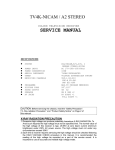
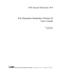
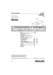
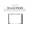
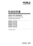
NXP TDA9351/53/61/63 XXX SERIES
SERVICE MANUAL
COLOUR TELEVISION
1
.
CONTENTS
1. safety precautions ………………………………………………………………………………………3
2.
block diagram ……………………………………………………………………………………………4
3. Replacement of memory IC ……………………………………………………………………………6
4. Service adjustment ……………………………………………………………………………………...6
5. ICs functional description ……………………………………………………………………………15
6. Test point waveform………………………………………………………………………………….…18
7. All ICs/transistors voltages…………………………………………………………………………….19
8. Purity / convergence adjustment……………………………………………………………………..20
9. KLX-PH22Z VER3.0 circuit diagram
10. KLX-PH22Z VER3.0 PCB
11. KLX-PH22Z .BOM
………………………………………………………………22
………………………………………………………………………….. 23
………………………………………………………………………………….. 24
2
.
SAFETY PRECAUTIONS
1.
The design of this product contains special hardware, many
circuits and components specially for safety purposes. For
continued protection, no changes should be made to the
original design unless authorized in writing by the
manufacturer. Replacement parts must be identical to those
used in the original circuits. Service should be performed by
qualified personnel only.
2.
Alterations of the design or circuitry of the products should
not be made. Any design alterations or additions will void
the manufacturer’s warranty and will further relieve the
manufacturer of responsibility for personal injury or property
damage resulting therefrom.
3.
Many electrical and mechanical parts in the products have
special safety-related characteristics. These characteristics
are often not evident from visual inspection nor can the
protection afforded by them necessarily be obtained by
using replacement components rated for higher voltage,
wattage, etc. Replacement parts which have these special
safety characteristics are identified in the parts list of
Service manual. Electrical components having such
features are identified by shading on the schematics
and by ( ! ) on the parts list in Service manual. The use
of a substitute replacement which does not have the same
safety characteristics as the recommended replacement
part shown in the parts list of Service manual may cause
shock, fire, or other hazards
4.
Don’t short between the LIVE side ground and
ISOLATED (NEUTRAL) side ground or EARTH side
ground when repairing. Some model’s power circuit is
partly different in the GND. The difference of the GND is
shown by the LIVE: ( ) side GND, ISOLATED (NEUTRAL) :
( ) side GND and EARTH : (
) side GND. Don’t short
between the LIVE side GND and ISOLATED (NEUTRAL)
side GND or EARTH side GND and never measure with a
measuring apparatus (oscilloscope etc.) the LIVE side GND
and ISOLATED (NEUTRAL) side GND or EARTH side GND
at the same time. If above note will not be kept, a fuse or
any parts will be broken.
5.
If any repair has been made to the chassis, it is
recommended that the +B setting should be checked or
adjusted (See ADJUSTMENT OF +B POWER SUPPLY).
6.
The high voltage applied to the picture tube must conform
with that specified in Service manual. Excessive high
voltage can cause an increase in X-Ray emission, arcing
and possible component damage, therefore operation under
excessive high voltage conditions should be kept to a
minimum, or should be prevented. If severe arcing occurs,
remove the AC power immediately and determine the cause
by visual inspection (incorrect installation, cracked or melted
high voltage harness, poor soldering, etc.). To maintain the
proper minimum level of soft X-Ray emission, components
in the high voltage circuitry including the picture tube must
be the exact replacements or alternatives approved by the
manufacturer of the complete product.
7.
Do not check high voltage by drawing an arc. Use a high
voltage meter or a high voltage probe with a VTVM.
Discharge the picture tube before attempting meter
connection, by connecting a clip lead to the ground frame
and connecting the other end of the lead through a 10kΩ
2W resitor to the anode button.
8.
When service is required, observe the original lead dress.
Extra precaution should be given to assure correct lead
dress in the high voltage circuit area. Where a short circuit
has occurred, those components that indicate evidence of
overheating should be replaced. Always use the
manufacturer’s replacement components.
9.
10. Isolation Check
(Safety for Electrical Shock Hazard)
After re-assembling the product, always perform an isolation
check on the exposed metal parts of the cabinet (antenna
terminals, video/audio input and output terminals, Control
knobs, metal cabinet, screwheads, earphone jack, control
shafts, etc.) to be sure the product is safe to operate without
danger of electrical shock.
11. The surface of the TV screen is coated with a thin film which
can easily be damaged. Be very careful with it when handle
the TV. Should the TV screen become soiled, wipe it with a
soft dry cloth. Never rub it forcefully. Never use any cleaner
or detergent on it.
(1)
(2)
3
Dielectric Strength Test
The isolation between the AC primary circuit and all metal
parts exposed to the user, particularly any exposed metal
part having a return path to the chassis should withstand a
voltage of 3000V AC (r.m.s.) for a period of one second.
(…Withstand a voltage of 1100V AC (r.m.s.) to an appliance
rated up to 120V, and 3000V AC (r.m.s.) to an appliance
rated 200V or more, for a periode of one second.)
This method of test requires a test equipment not generally
found in the service trade.
Leakage Current Check
Plug the AC line cord directly into the AC outlet (do not use
a line isolation transformer during this check.). Using a
“Leakage Current Tester”, measure the leakage current
from each exposed metal part of the cabinet, particularly
any exposed metal part having a return path to the chassis,
to a known good earth ground (water pipe, etc.). Any
leakage current must not exceed 0.5mA AC (r.m.s.).
However, in tropical area, this must not exceed 0.2mA AC
(r.m.s.).
●Alternate Check Method
Plug the AC line cord directly into the AC outlet ( do not use
a line isolation transformer during this check.). Use an AC
voltmeter having 1000 ohms per volt or more sensitivity in
the following manner. Connect a 1500 Ω 10W resistor
paralleled by a 0.15 μ F AC-type capacitor between an
exposed metal part and a known good earth ground (water
pipe, etc.). Measure the AC voltage across the resistor with
the AC voltmeter. Move the resistor connection to each
exposed metal part, particularly any exposed metal part
having a return path to the chassis, and measure the AC
voltage across the resistor. Now, reverse the plug in the AC
outlet and repeat each measurement. Any voltage
measured must not exceed 0.75V AC (r.m.s.). This
corresponds to 0.5mA AC (r.m.s.).
However, in tropical area, this must not exceed 0.3V AC
(r.m.s.).
This corresponds to 0.2mA AC (r.m.s.)
.
2 TV Block diagram
TDAXXXX
video
TUNER
SAW
S
TRAP
IF IN
R/Y IN
Y
RF AGC
G/U IN
Cr
B/V IN
Cb
Vo
V2i
video
4052
video
V1i
video
CVBSINT
Y
S-VHS
CHROMA
IFVO OUT
video
C
CVBS/Y IN
ALi2
24C08
ALi1
audio
z
z
bus
SDA
SCL
ARi2
audio
ARi1
AUDIO OUT
V OUT
IK
RGB OUT
H OUT
4052
ALo
ARo
audio
AN7522
110V
26V
POWER
UNIT
14V
-14V
8V
3.3V
V IN
H IN
180V
LA78040/41/
TDA8174A
H OUT
heat
H OUT
V OUT
CRT PCB
SCREEN
FOCUS
DY
4
audio
CRT
Vi1
OUT1OUT1+
Vi2
OUT2OUT2+
.
Block diagram TDA93xx/83xx series with mono intercarrier sound demodulator
5
3.REPLACEMENT OF MEMORY IC
1. MEMORY IC.
This TV uses memory IC. In the memory IC are memorized data for correctly operating the video and
deflection circuits.
When replacing memory IC, be sure to use IC written with the initial value of data.
2. PROCEDURE FOR REPLACING MEMORY IC
(1) Power off
Switch the power off and unplug the power cord from AC outlet.
(2) Replace IC
Be sure to use memory IC written with the initial data values.
(3) Power On
Plug the power cord into the AC outlet and switch the power On.
(4) Check and set system default value:
1) Press “MENU” key followed by digits '6''4''8' and '3'. then Press “TEST” key on the Remote
control unit for factory used.
2) The red “M”or”factory” will be displayed on the screen, repeat this and it will changed as follow:
normal-M(factory)-BUS open-normal..
3) Press digital key, (Mkey) and corresponding on-screen display will be appeared.
4) Check the setting value of the SYSTEM default value of Table below. If the value is different,
select items by [CH+]/[CH-] keys and set value by [VOL+]/[VOL-] keys.
5) Press “STANDBY” key again and return to the normal screen.
4.SERVICE ADJUSTMENT
B1 POWER SUPPLY
1. Receive normal colour bar signal.
2. Connect DC voltmeter to VD524- and isolated ground.
3. Adjust potentiometer in power unit to get the voltage as 110V ±1.0V for 21 inch hereinafter,
FOCUS ADJUSTMENT
1. Receive a crosshatch signal.
2. While watching the screen, adjust the FOCUS VR to make the vertical and horizontal lines as fine and
sharp as possible.
BUS CONTROL ADJUSTMENT
TDA9351/9353:to enter BUS control mode, Press “MENU” key followed by digits '6''4''8' and '3'. then
press digit Press “0” to “9“ key, (Mkey) and corresponding on-screen display will be appeared.
TDA8370:to enter BUS control mode, Press “MENU” key followed by digits '6''4''8' and '3'. then Press
“TEST” key on the Remote control unit twice for factory used(or press digits '6''4''8' and '3' twice.). and then
press digit Press “0” to “9“ key, (Mkey) and corresponding on-screen display will be appeared.
On TV screen “TEST” will be indicated, this means entered bus control mode.
And press following key, each function will be available.
6
Remote Hand Unit keys
[M1]
c
[M2]
d
[M4]
[M5]
f
i
[M8]
[M7]
g
j
[M0]
b
[M3]
e
[M6]
h
k
[M9]
MENU8
V SLOPE
V SHIFT
V AMP
V SCOR
H SHIFT
31
31
31
31
31
Geometrical adjustment
MENU8 (9351)/servise 1(8370)
Receive PAL standard Complete pattern signal.
Adjustment steps:
a) Adjust V. SLOPE, to the center horizontal line just appeare from half bottom shadow.
b) Adjust V. SIZE, to get 90% of vertical picture contents would be displayed on CRT.
c) Adjust V. SHIFT, the center horizontal line correspond to CRT vertical center.
d) Adjust H.SHIFT, to get the picture horizontal center correspond to CRT horizontal center.
Receive NTSC signal and repeat above
AGC Adjustment.
MENU7 (9351)/servise 2(8370)
Receive 60dBμ(1mV)VH colour bar pattern signal,adjust AGC value(voltage from high to low),to noise
reduce gradually and just disappeared point.
CRTcut off and white balance adjustment.
MENU9 (9351)/B W BALANCE(8370)
Receive white signal.
a) CRT cut off adjustment.
1. Select “SC”, then automatically vertical scan will be stopped.
2. Adjust SCREEN control on Flyback transformer to get the darkest single horizontal line (red,
green, or blue, sometimes shows more yellow, more purple or more white).
b) White balance adjustment.
1. Select RD/BD menu.
2. Adjust RD/BD to get colour temperature as x=281, y=311
c) Sub-Brightness adjustment. (Use stair case signal)
1. Select SB menu.
2. Adjust SB to get the darkest step being cutoff.
7
ICs Default Settings
1. TDA9351/9353
MI
M0
Items
Vari
Prese
discription
able
t
AVL
ON/OFF
ON
Auto volume control select on menu.on:open;off:close.
FSL
ON/OFF
ON
Vertical sync slice level select.off:auto;on: 60% of complex sync
FMWS
0-2
0
FM demodulation band width.0:standard(225khz);1: for over FM
modulation(450KHz);2:for over FM modulation(600KHz)
FFI
ON/OFF
OFF
IF PLL filter.on:short time constant;off:normal
OSO
ON/OFF
ON
Decreasing bright spot when switch off stay at the vertical over scan
period .ON:open;OFF:close.
FCO
ON/OFF
OFF
Forced color system. On:only for single color system(for example
VCR); off:normal
M1
M2
WOOFER
ON/OFF
OFF
Woofer select on menu.on:open;off:close.
DVD DELAY
0-8
2
Delay of turning to TV from DVD
DVD/VCD
ON/OFF
OFF
Display on screen.on:DVD;OFF:VCD.
BAND
0~2
2
Tuner band mode select,see attached table 1
AV OPT
ON/OFF
OFF
AV control logic option,see table 2
AV CFG*
0~8
3
AV input stuts select, see table 2
NTSC MX
USA/JAP
USA
NTSC matrix select(USA or JAPAN)
VIDEO OUT
IF/CVBS
CVBS
AV output mode select:TV /display on screen
PRO
0-3
0
Sharp the boardline
PIN5
NTSC
Compatible with other hardware, see table3
PIN7
VOL1
Compatible with other hardware, see table3
PIN8
MUTE
Compatible with other hardware, see table3
START TIME
6-15 S
8
Delay time after power on
VISION IF
38/38.9/4
38.9M
IF select
5.75/58.7
5
DK
ON/OFF
OFF
Sound system select
BG
ON/OFF
ON
Sound system select
I
ON/OFF
OFF
Sound system select
M
ON/OFF
OFF
Sound system select
SIF PREFER
DK/I/BG/
BG
Sound system priority select when Auto scan
M
AUTO SOUND
ON/OFF
ON
Sound system auto identify when auo scan
POWER OPT
0-2
2
Switch on mode,0:standby,1:power on;2:remember last time.
TXT DEF
0-3
0
Text language selset
TXT BRI
0-63
63
Text brightness set
SPANISH BIT
ON/OFF
OFF
Spanish text bit
ENGLISH
ON/OFF
ON
Language option
ARABIC
ON/OFF
OFF
Language option
MI
M3
8
M4
PERSIAN
ON/OFF
OFF
Language option
TURKISH
ON/OFF
OFF
Language option
FRANCE
ON/OFF
OFF
Language option
RUSSIA
ON/OFF
OFF
Language option
HUNGARY
ON/OFF
ON
Language option
SPANISH
ON/OFF
ON
Language option
CROATIA
ON/OFF
ON
Language option
GREECE
ON/OFF
ON
Language option
PORTUGUESE
ON/OFF
ON
Language option
BUGIARIA
ON/OFF
ON
Language option
SERBIA
ON/OFF
ON
Language option
ITALY
ON/OFF
ON
Language option
ROMANIAN
ON/OFF
ON
Language option
POLISH
ON/OFF
ON
Language option
Items
Variable
Preset
SUBCON
0~63
63
Subsidiary contrast setting
SUBCOL
0~63
63
Subsidiary color setting
SUBSHP
0~63
63
Subsidiary sharp setting
SUBTINT
0~15
15
Subsidiary tint setting
YDLY PAL
0~15
12
Y delay time setting of PAL
YDLY NTSC
0~15
12
Y delay time setting of NTSC
YDLY SEC
0~15
12
Y delay time setting of SECAM
YDLY AV
0~15
12
Y delay time setting of AV
UOC VOL SW
ON/OFF
OFF
Audio output mode option.on:output controlled by volume;off:not
controlled.
UOC VOL
0-63
63
Audio output range setting of pin44
TDA9874
0-30
5
Output range adjusting of TDA9874
CATHODE
0~15
15
Cathode voltage setting
SC BRI
0~63
32
The single horizontal line brightness setting
TINT RANGE
0-63
31
Tint adjust range setting
OSD VPOS
0~63
53
OSD position setting of vertical
OSD HPOS
0~59
15
OSD position setting of horizontal
WIDE
0~63
15
Vertical range setting of wide screen mode
ZOOM
0~63
59
Vertical range setting of zoom mode
NENU TITLE
0~6
3
Color setting of menu title
MI
HALFTONE
0-2
1
Halftone setting of menu
M6
SHIPMODE
GAIN
M5
Ship mode setting option
9
SEARCH
0-3
1
Search speed setting.o:slow;3:fast
PWL
0-15
15
White peak limit
OSD
0-3
0
OSD contrast setting.0:bitght;3:dark
BLUE STR.
ON/OFF
ON
Blue level stretch option
BSD
ON/OFF
ON
Black level stretch range.ON:30 IRE;OFF:20IRE.
AAS
ON/OFF
ON
Black level actived area.ON:no more than 10%of black
SPEED
CONTRAST
background;OFF:no more than 20% of black background.
CORING
M7
M8
M9
0-3
0
Coring and decrease nosie.0:off.
AGC-TOP
0-63
24
RF AGC adjusting
AGC-SPEED
0-3
1
AGC delay time adjusting
LOGO OPT
ON/OFF
OFF
LOGO option
VOL6
0-63
17
Volume setting of 10%
VOL16
0-63
32
Volume setting of 25%
VOL32
0-63
48
Volume setting of 50%
VOL63
0-63
63
Volume setting of 100%
7KEYS
ON/OFF
OFF
“POWER”key option of key board
X RAY
ON/OFF
OFF
X RAY protect function option
OSVE
ON/OFF
OFF
AKB detect line hide option(supported by TDA9353/63)
HCO
ON/OFF
OFF
Auto horizenal range revise option(supported by TDA9353/63)
FREQUENCY
50HZ
60HZ
Display vertical frequency automaticly
VSLOPE
0~63
31
31
Vertical slope adjusting
VSHIFT
0~63
31
31
Vertical shift adjusting
VAMP
0~63
31
31
Vertical size adjusting
VSCOR
0~63
31
31
Vertical correct adjusting
HSHIFT
0~63
31
31
Horizontal shift adjusting
RGBHS
0~63
31
Vertical shift adjusting of RBG/YUV
RGB HPOS
0~63
31
OSD horizontal shift adjusting of RBG/YUV
EW WIDTH
0~63
31
Horizontal range adjusting
EW PARA
0~63
31
East-west curve adjusting
UP CORNER
0~63
31
Up conner adjusting
LO CORNER
0~63
31
Low conner adjusting
H-PARA
0~63
31
Paralleloqram adjusting
H-BOW
0~63
31
Bow adjusting
EW-TRAPE
0~63
31
Trapezoid adjusting
BT
0~63
48
Brightness adjusting of white balance
CT
0~63
48
Contrast adjusting of white balance
OFF
Single horizontal line.open by “V+”;closed by “V-”
SC
RB
0~63
32
Red cut adjusting
GB
0~63
32
Green cut adjusting
10
RD
0~63
32
Red drive adjusting
GD
0~63
32
Green drive adjusting
BD
0~63
32
Blue drive adjusting
SB
0~63
40
Sub-brightness adjusting
ATTACHED TABLE1
BAND=0
BAND=1
BAND=2
PIN10(B2)
PIN11(B1)
PIN10(B2)
PIN11(B1)
PIN10(B2)
PIN11(B1)
VL
0
0
0
1
1
0
VH
1
0
1
0
0
1
U
0
1
1
1
1
1
TABLE2
AV OPTION:MENU1→AV CFG;
O=TV→AV;1=TV→AV1→AV2;2=TV→AV1→AV2→S-VIDEO;3=TV→AV1→AV2→S-VIDEO→YUV;
5= TV→AV→S-VIDEO;6= TV→AV→S-VIDEO→YUV;7= TV→AV→YUV;8=TV→EURO;
9=TV→AV→EURO
When“AV OPT”is setting “OFF”,the logic table of AV control
MODE
TV
AV2
AV/AV1/YUV/EURO(RGB)
SVHS
Pin62
L
L
H
H
Pin63
L
H
L
H
When“AV OPT”is setting “ON”,the logic table of AV control
MODE
TV
AV2
AV/AV1/YUV/EURO(RGB)
SVHS
Pin62
H
L
L
L
Pin63
H
H
L
L
TABLE3
Pin5,pin7,pin8 is variable for compating with other hardware
NTSC
Control SAW filter ,switch between M
VOL2
PWM control output for left AMP.
and N
DVD
Output for DVD&TV cabine control
VOL1
PWM control output for right AMP.
SCART
Scart detect level input
WOOFER
For woofer controlling
MUTE
For audio mute mode
MUTE2
For mute mode 2
LED
For LED controlling
SV-DT
S-VIDEO detect level input
BAND3
For band3 controlling
5060
Output for 50/60Hz alternate
11
2. OM8370
B/W BALANCE
MI
Items
Vari
Prese
discription
able
t
DRI R
0~63
32
RED DRIVE
DRI G
0~63
32
GREEN DRIVE
DRI B
0~63
32
BLUE DRIVE
CUT R
0~63
32
RED CUT
CUT G
0~63
32
GREEN CUT
BT
0~63
32
Brightness adjust of white balance
CT
0~63
32
contrast adjust of white balance
Note: press "MUTE" To enter the single horizontal line mode,and press again exit.
S0
POW
0-2
1
Switch on mode,0:standby,1:power on;2:remember last time.
LOGO
ON/OFF
OFF
LOGO option
DRCS LOAD
ON/OFF
OFF
Speicel letter load for logo(supportted by 24C16,set OFF normally)
SAVER
ON/OFF
OFF
Option of screen saver
MENU BG
0~2
2
Background of menu(0:no;1:blue;2:half tone)
AV OPT
ON/OFF
ON
AV control logic level option
OFF
ON
S1
S2
TV
AV1
AV2
SVHS
OTHER
PIN62
0
1
0
1
1
PIN63
0
0
1
1
0
PIN62
1
0
0
0
0
PIN63
1
0
1
0
0
AV2
ON/OFF
ON
Option of AV2
SVHS
ON/OFF
OFF
Option of SVHS
YUV
ON/OFF
OFF
Option of YUV
SCART
ON/OFF
OFF
Option of SCART
DVD
ON/OFF
OFF
Option of DVD
DVD SRC
V/S/YUV
V
Select of DVD input mode
DVD LOGIC
0-3
3
DVD logic output level select(pin62 63)
50HZ
Display vertical frequency automaticly
FREQUENCY
H PH
0~63
31
Horizontal shift adjusting
V SL
0~63
24
Vertical slope adjusting
V SH
0~63
21
Vertical shift adjusting
V SI
0~63
33
Vertical size adjusting
V SC
0~63
27
Vertical correct adjusting
H PH YUV
0~63
31
Horizontal shift adjusting of YUV/RGB
AGC
0~63
24
Adjusting of RF AGC
COOL R
0~63
30
Cool color temperature adjusting of red
COOL G
0~63
32
Cool color temperature adjusting of green
COOL B
0~63
42
Cool color temperature adjusting of blue
WARM R
0~63
42
Warm color temperature adjusting of red
WARM G
0~63
32
Warm color temperature adjusting of green
12
S3
S4
WARM B
0~63
30
Warm color temperature adjusting of blue
BR-YUV
0~63
32
Bias voltage of red for YUV
BG-YUV
0~63
32
Bias voltage of green for YUV
WIDE
0~63
17
Vertical size adjusting of wide mode
ZOOM
0~63
50
Vertical size adjusting of zoom mode
VP
7~63
38
Vertical shift of OSD
HP
0~63
30
Horizonol shift of OSD
HP-YUV
0~30
30
Horizonol shift of YUV
OSD BRI
0~3
0
Brightness of OSD
AGC-SPEED
0-3
1
AGC delay time adjusting
POW ON TIM
6-15
8
Powe on delay on time setting
VIDEO OUT
IF/CVBS
CVBS
AV out mode option(IF:TV;CVBS:screen)
PIN5
NTSC
Compatible with other hardware, see table*
PIN7
VOL1
Compatible with other hardware, see table*
PIN8
MUTE
Compatible with other hardware, see table*
AKB
ON/OFF
ON
Auto black level adjusting
NBL
ON/OFF
OFF
Auto detect of black current
RC FORMAT
NEC/RC5
NEC
Code select of Renote Control
Note:wrong select may cause useless of RC
KEYBOARD
SANYO/
SANY
PHILIPH
O
Keyboard select
S
MONO
* For compatible of other hardware, there are different functions of pin 5,7,8.
S5
woofer
For woofer control
Vol2
Volume PWM control of right AMP.
Vol1
Volume PWM control of left AMP.
Band3
For band control for the third pin of tuner
NTSC
For SAW filter control
SCART
Detect signal input of SCART
DVD
Output control level for DVD
MUTE
Control signal for MUTE
5060
Control signal for 50/60 switch
MUTE2
Control signal for MUTE2
SV-DT
Detect signal For S-Video
ENGLISH
ON/OFF
ON
Language option
FRENCE
ON/OFF
ON
Language option
RUSSIAN
ON/OFF
ON
Language option
TURKISH
ON/OFF
ON
Language option
FARSI
ON/OFF
ON
Language option
ARABIC
ON/OFF
ON
Language option
BULGARIAN
ON/OFF
ON
Language option
RUMANNIAM
ON/OFF
ON
Language option
SPANISH
ON/OFF
ON
Language option
13
S6
PORTUGUESE
ON/OFF
ON
Language option
ITALIAN
ON/OFF
ON
Language option
GERMAN
ON/OFF
ON
Language option
DUTCH
ON/OFF
ON
Language option
SWEDISH
ON/OFF
ON
Language option
NORWEGIAN
ON/OFF
ON
Language option
HUNGARIAN
ON/OFF
ON
Language option
POLISH
ON/OFF
ON
Language option
CZECH
ON/OFF
ON
Language option
SLOVENE
ON/OFF
ON
Language option
CROATIAN
ON/OFF
ON
Language option
MACEDONIAN
ON/OFF
ON
Language option
SERBIAN
ON/OFF
ON
Language option
GREEK
ON/OFF
ON
Language option
Items
Variable
Preset
UOC VOL SW
0~63
63
Subsidiary contrast setting
UOC/PWM
0~63
63
Subsidiary color setting
VOL10
0~100
25
Volmule of diagram 25%
VOL25
0~100
50
Volmule of diagram 50%
VOL50
0~100
75
Volmule of diagram 75%
VOL100
0~100
100
Volmule of diagram 100%
WOOFER
ON/OFF
OFF
Woofer option on menu
TDA9860
ON/OFF
OFF
Woofer output mode select (from TDA9860 or PWM)
VOL
WOOF
TDA9874
OFF:PWM;on:TDA9860.
ON/OFF
OFF
Gain of TDA9874 output
AGN
ON/OFF
OFF
Gain of FM output .OFF:normal;no:+6dB
IF
38/38.9/
38.9M
IF setting
0
Band width of FM demodulation.0:standard(225kHz) ;1:for FM
GAIN
S7
45.75/
58.75
FMWS
0~2
over modulation (450kHz);2:over modulation (600kHz)
VST
0~2
0
VST band control option
BAND3
Band
VHFL
0
0
opt=0
VHFH
1
0
UHF
0
1
Band
VHFL
0
1
opt=1
VHFH
1
0
UHF
1
1
14
Band
VHFL
1
0
0
opt=2/
VHFH
0
1
0
band
UHF
1
1
1
3
FST BAND
ON/OFF
OFF
OFF:TABLE1;ON:TABLE2. NOTE*
FST LH
Frequency of H band setting*
FST HU
Frequency of U band setting*
SECAM
ON/OFF
ON
SECAM system option
DK
ON/OFF
ON
Sound system option
I
ON/OFF
ON
Sound system option
M
ON/OFF
OFF
Sound system option
BG
ON/OFF
ON
Sound system option
AUTO
ON/OFF
ON
Sound system auto indefine for auto search
DK/I/BG/
BG
Perfer sound system for auto search
SOUND
SIFPREFER
M
S8
SUB CON
0~63
32
Subsidiary contrast setting
SUB BRI
0~63
32
Subsidiary brightness setting
SUB COL
0~63
32
Subsidiary color setting
SUB SHA
0~63
32
Subsidiary sharp setting
SUB TINT
0~31
16
Subsidiary tint setting
YDLY PAL
0~15
2
Y delay time setting of PAL
YDLY NTSC
0~15
2
Y delay time setting of NTSC
YDLY AV
0~15
2
Y delay time setting of AV
CATHE
0~15
8
Cathode drive level of CRT
SC.BRI
0~63
8
Brightness of the single horizontal line mode
PWL
0~15
15
Limit of peak of white level
5. ICs functional description
UOC TDA93XX/83XX
SYMBOL
PIN
DESCRIPTION
STAND BY output.
1
In STAND BY mode, high level (Power OFF).
For Power ON this pin will be reduced to low.
SCL
2
I2C-bus clock line
SDA
3
I2C-bus data line
TUNING
4
tuning Voltage (Vt) PWM output
P3.0/NTSC SW
5
Port 3.0 or NTSC output/SCART SW input, Forced NTSC selection,
Low-level output, otherwise High output.
KEY
6
Control keys input *3
VOL
7
Sound Volume control PWM output
MUTE
8
Sound mute output
VSSC/P
9
Digit ground for μ-controller core and periphery
BAND1
10
Tuner Band selection output
BAND2
11
Tuner Band selection output
VSSA
12
Analog ground of teletext decoder and digital ground of TV-processor
15
SECPLL
13
SECAM PLL decoupling
VP2
14
2nd supply voltage TV-processor(+8V)
DECDIG
15
decoupling digital supply of TV-processor
PH2LF
16
Phase-2 filter
PH1LF
17
Phase-1 filter
GND3
18
Ground 3 for TV-processor
DECBG
19
Band gap decoupling
AVL/EWD
20
Automatic volume leveling /EAST-WEST drive output
VDRB
21
Vertical drive B output
VDRA
22
Vertical drive A output
IFIN1
23
IF input 1
IFIN2
24
IF input 2
IREF
25
Reference current input
VSC
26
Vertical sawtooth capacitor
TUNER AGC
27
Tuner AGC output
AUDEEM/SIFIN1 *1
28
Audio deemphasis or SIF input
DECSDEM/SIFIN2
29
decoupling sound demodulator or SIF input 2
GND2
30
ground 2 for TV processor
SNDPLL/SIFAGC *1
31
narrow band PLL filter or AGC sound IF
AVL/SNDIF/REF0/
AMOUT *1
32
Automatic Volume Levelling / sound IF input / subcarrier reference output / audio
HOUT
33
horizontal output
FBISO
34
flyback input/sandcastle output
AUDEXT/QSSO/
AMOUT *1
35
external audio output / QSS intercarrier out
EHTO
36
EHT/overvoltage protection input
PLL IF
37
IF-PLL loop filter
IFVO/SVO
38
IF video output / selected CVBS output
VP1
39
supply voltage TV processor
CVBS INT
40
internal CVBS input
GND1
41
ground for TV processor
CVBS/Y
42
CVBS/Y input
CHROMA
43
C input
AUDOUT/AMOUT *1
44
audio output /AM audio output (volume controlled)
INSSW2
45
2nd RGB / YUV insertion input
R2/VIN
46
2nd R input / V (R-Y) input / PR input
G2/YIN
47
2nd G input / Y input
B2/UIN
48
2nd B input / U (B-Y) input / PB input
BCLIN
49
beam current limiter input
BLKIN
50
black current input / V-guard input
RO
51
Red output
GO
52
Green output
BO
53
Blue output
VDDA
54
analog supply of Closed Caption decoder and digital supply of TV-processor (3.3
deemphasis
16
V)
VPE
55
OTP Programming Voltage
VDDC
56
digital supply to core (3.3 V)
OSCGND
57
oscillator ground supply
XTALIN
58
crystal oscillator input
XTALOUT
59
crystal oscillator output
RESET
60
reset
VDDP
61
digital supply to periphery (+3.3 V)
P1.0/INT1
62
TV/AV (AV1) / AV2 /S-VHS mode Output.
P1.1/T0
63
TV/AV (AV1) / AV2 /S-VHS mode Output.
P1.2/INT0
64
Remote control signal input.
Note
1. The function of pin 20, 28, 29, 31, 32, 35 and 44 is dependent on the IC version (mono intercarrier FM demodulator
/QSS IF amplifier and East-West output or not) and on some software control bits. The valid combinations are given in
table 1.
2. the vertical guard function can be controlled via pin 49 or pin 50. the selection is made by means of the
IVG bit in subaddress 2BH.
TABLE 1
IC version
FM-PLL version
East-West
QSS version
N
Y
N
Y
Y/N
CMB1/CMB0
00
01/10/11
00
01/10/11
00
-
-
-
-
-
01/10/11
00
01/10/11
bits
AM bits
AVL
Pin 20
EWD
0
1
-
AVL
AUDEEM
SIFIN1
Pin 29
DECSDEM
SIFIN2
Pin 31
SNDPLL
SIFAGC
SNDIF(1)
REFO(2)
AVL/SNDIF(1)
Pin 35
AUDEXT
Pin 44
AUDOUT
REFO(2)
1
EWD
Pin 28
Pin 32
0
AMOUT
REFO(2)
AUDEXT
QSSO
AMOUT
AMOUT
REFO(2)
AUDEXT
QSSO
AMOUT
Controlled AM or audio out
Note
1. When additional (external) selectivity is required for FM-PLL system pin 32 can be used as sound IF input.
This function is selected by means of SIF bit in subaddress 28H.
2. the reference output signal is only available for the CMB1/CMB0 setting of 0/1. for the other settings this pin is
a switch output(see also 5 table 67).
Pin No. 6: Control keys input voltage
Function
POWER
MENU
TV/AV
V-
V+
P-
P+
Voltage
11/1613/16VDD
9/1611/16VDD
7/169/16VDD
5/167/16VDD
3/165/16VDD
1/163/16VDD
01/16VDD
AN17821A/17823A
Function : audio output
17
Symbol
PIN
Function
Symbol
PIN
Function
Vcc
1
Power supply
GND
7
ground
Out 1 (+)
2
Ch 1 output (+)
In 2
8
Ch 2 input
GND(out 1)
3
Ch 1Ground
VOL
9
Volume Control
Out 1 (-)
4
Ch 1 output (-)
Out 2 (-)
10
Ch 2 output (-)
Standby
5
Mute input
GND(out 2)
11
Ch 2 Ground
In 1
6
Ch 1 input
Out 2 (+)
12
Ch 2 output (+)
Note: AN17823A is pin 1 to 9, AN17821A is pin 1 to 12.
LA78040/78041/TDA8172A
Function : vertical output
Symbol
PIN
Function
Symbol
PIN
Function
INV IN
1
Input
V OUT
5
Vertical output
VCC1
2
Power
VCC2
6
Output power supply
PUMP UP
3
Pump up power
NON INV IN
7
Negative feedback
GND
4
Ground
6. Test point Waveforms
2.6Vpp
H
TDA93XX PIN38
95Vpp
H
1.2Vpp
H
TDA93XX PIN40
95Vpp
CRT KR
H
CRT KG
1Vpp
0.8Vpp
V
V
TDA93XX PIN21
TDA93XX PIN22
22Vpp
300Vpp
H
HEATER
H
T511 PIN7
3.8Vpp
2.5Vpp
H
TDA93XX PIN53
H
TDA93XX PIN52
95Vpp
0.9Vpp
H
CRT KB
1.3Vpp
TDA93XX PIN59
18
H
TDA93XX PIN33
2.7Vpp
H
V451 B
2.5Vpp
H
TDA93XX PIN51
5Vpp
H
TDA93XX PIN34
1000Vpp
H
V451 C
7. IC voltages
TDA93XX
PIN
1
2
3
4
5
6
7
8
9
10
11
12
13
14
15
16
V
2.8
3.8
3.6
3.3
3.5
3.5
0.1
0.1
0
5.4
0.1
0
2.3
8
5
3
PIN
17
18
19
20
21
22
23
24
25
26
27
28
29
30
31
32
V
4
0
4
0.9
0.7
0.8
1.9
1.9
3.9
3.8
1.6
3.2
3.4
0
2.4
0.1
PIN
33
34
35
36
37
38
39
40
41
42
43
44
45
46
47
48
V
0.6
0.5
3.7
1.7
2.4
3.1
8
3.8
0
3.4
1.5
3.6
2.3
2.6
2.6
2.6
PIN
49
50
51
52
53
54
55
56
57
58
59
60
61
62
63
64
V
2.3
7.2
2.7
2.7
2.7
3.5
0
3.5
0.1
1.7
1.8
0
3.5
0.1
0.1
5
LA76040
PIN
1
2
3
4
5
6
7
V
0.7
15
-12
-15
0.3
15.9
-0.07
AN 17821A
PIN
1
2
3
4
5
6
7
8
9
10
11
12
V
12
7
0
7
3.3
1.4
0
1.4
0
7
0
7
TDA9859
PIN
1
2
3
4
5
6
7
8
9
10
11
12
13
14
V
4.0
0
4.0
8.0
4.0
8.0
4.0
0
4.0
4.0
4.0
4.0
4.0
4.0
PIN
15
16
17
18
19
20
21
22
23
24
25
26
27
28
V
4.0
4.5
4.6
4.0
4.0
4.0
4.0
4.0
4.0
4.0
0
4.0
4.0
4.0
PIN
29
30
31
32
V
4.0
4.0
0
4.0
19
8. PURITY / CONVERGENCE ADJUSTMENT
PURITY ADJUSTMENT
1.
Demagnetize CRT with the demagnetizer.
2.
Loosen the retainer screw of the deflection yoke.
3.
Remove the wedges.
4.
Input a green raster signal from the signal generator,
and turn the screen to green raster.
5.
WEDGE
DEFLECTION YOKE
P
CRT
4 6
Move the deflection yoke backward.
P/C MAGNETS
6.
Bring the long lug of the purity magnets on the short
lug and position them horizontally. (Fig2)
7.
Adjust the gap between two lugs so that the GREEN
RASTER will come into the center of the screen. (Fig.
3)
8.
Move the deflection yoke forward, and fix the position
of the deflection yoke so that the whole screen will
become green.
9.
Insert the wedge to the top side of the deflection yoke
so that it will not move.
P: PURITY MAGNET
4: 4-POLES (convergence magnets)
6: 6-POLES (convergence magnets)
Fig. 1
PURITY MAGNETS
Long lug
10. Imput a crosshatch signal.
11. Verify that the screen is horizontal.
12. Input red and blue raster signals, and make sure that
purity is properly adjusted.
Short lug
Bring the long lug over the short lug
and position them horizontally.
Fig. 2
(FRONT VIEW)
GREEN RASTER
CENTER
Fig. 3
20
STATIC CONVERGENCE ADJUSTMENT
1. Input a crosshatch signal.
2. Using 4-pole convergence magnets, overlap the red
and blue lines in the center of the screen (Fig. 1) and
turn them to magenta (red/blue).
3. Using 6-pole convergence magnets, overlap the
magenta (red/blue) and green lines in the center of the
screen and turn them to white.
(FRONT VIEW)
4. Repeat 2 and 3 above, and make the best
convergence.
Fig. 1
DYNAMIC CONVERGENCE ADJUSTMENT
(FRONT VIEW)
RED
1. Move the deflection yoke up and down and overlap
lines in the periphery. (Fig. 2)
2. Move the deflection yoke left to right and overlap the
lines in the periphery. (Fig. 3)
3. Repeat 1 and 2 above, and make the best
convergence.
GREEN BLUE
BLUE
RED
GREEN
GREEN
RED
BLUE
BLUE GREEN RED
Fig.2
(FRONT VIEW)
After adjustment, fix the wedge at the original position.
Fasten the retainer screw of the deflection yoke.
Fix the 6 magnets with glue.
RED GREEN BLUE
BLUE GREEN RED
RED
GREEN
BLUE
BLUE
GREEN
RED
Fig. 3
21
Vcc
Ch1 out
GND
Ch1 out
Standby
Ch1 in
GND
Ch2 in
Volume
5
4
3
2
8
9
Ch2 out 11
10
R604
270K
B6
8V
C612
10uF*
V602
2SC1815Y
R614
68K
R612
18K
C613
10uF
R616
47K
C604
0.01uF
R609
47K
C606
0.01uF
D911
1N4148
4
R932 47
G
3
R916 47
B
2
R911 47
330p
R928
1/2W/2.7K
R935
2WSJ12K
V933
BF421
330 C931
TUNING
SW/NTSC
32
31
30
29
28
27
26
25
24
23
22
21
20
19
18
17
C704 0.01uF
C709 0.01uF
F
FOUSE
51
49
50
48
47
46
45
44
43
42
41
O
R509 15k
0
R502
8D-11
R513
3W 68
D506
FR154
D508
1N4148
C502
AC280V/0.1uF
C522
2A472
C514
FK0.1u
C501
AC280V/0.1uF
V501
2SA1015
R516
3.3k
C518A
2A153
R506
2.7K
TJC1-2A
R501
1/2W 120K
C509
CL21 2A153
FU501
T3.15A
1
3
2
B4
+15V
C306
25V/470u R572
2W 27
D555
FR154
C553
25V1000uF
D552
FR154
B9
11V
270k*
R316
IN
78L05
C567
OUT220uF
R701
1/4W27
B5
5V
GND
C716
47uF
C112
0.01uF
V563
2SD882
R564
2WDJ2.2
B6
8V
C554
16V470uF
D704
D703
1N4148 1N4148
C562
35V/470uF
R514
1/2WRI12M
C566
B8
27V 16V47uF
D556
FR154
R563
2WDJ0.47
3
B2
16V
D559
HZ9B2/8.7V
PPC-AMP
B1
3.6V
C314
35V/470uF*
C312
0.1u*
R317
1k*
C311 R319
0.1u* 18k*
R311
39k*
D550
1N4148
R321
2.7k*
R322
R320
39k*
R445
1W 10*
4.7k*
R323
2.7k*
R454
2W270
ABL
R482
10K
R302
47K
V305
2SC1815
R305
15K
V301
2SC1815
R301
8.2K
R304
4.7K
R331
10K
V304
2SC1815
R334
1K
RP303
50K
R306
4.7K
PPC-PHASE R332
1K
R309
22K
R455
27K
R307 C302
1.8K 10uF
MAIN BOARD
5
6
4
B+
110V
C437
630V0.047uF*
8
R561
1
2
6
5
3
29"短管:BSC26-01N4010F
BSC26-N2143
樱发
10
4
9
3WSJ1
C403
160V/47uF
D461
1N4148
ATTENTION:
(1)2SC:2SC536-E/F/G,2SC1815-O/Y/GR;
(2)D:1S1555;1N4148;1S2473;1S2076;D5442;
(3)2SA:2SA608;-E/F;2SA1015-O/Y/GR;
(4)0.01:CT1-08B-2F4-63V-0.01uF-Z
(5)KK470:CT1-06B-2B4-63V-470p-K
(6)FFXXX:CL11-63V-XXXuF-K
(7)200NJXXX:CBB22-200V-XXXuF-J
(8)1500MJXXX:CBB12-1600V-XXXuF-J
7
C
T471
BSC25-N0832
BSC25-T1010A
BSC24-01N4014K
Flyback Transformer
R486
C484
1000pF
R308
6.8K
3
4
7
R465
V303
2SC1815
R310
6.8K
R481
10K
D481
1N4148
C481
16V/47uF
560K
R303
1K
C601
25V1000UF
4
C402
250V/10u
B6
8V
R456
100K
EHTO
C701
47uF
D452
FR305*
B10
180V
R401
1/2W220K
C307
50v4.7u*
V303
2SD2012*
D311
1N4148*
B8
27V
L311
410uH*
CDS
R335
47K
C301
47uF
R568
1K
R318
5.6k*
RP312
10K*
V312
2SA1015*
V302
2SC1815
V562
2SA1015
HORIZ-SIZE
RP311
50K*
R314
R571
22K
8.2k*
V565
78L05
R312
10k*
C437A
TXP-5
V401
2SC2383
V552
2SC1815
R557
1/2WDJ150k
D562
HZ6C3/6.2V(日立)
R313
100k*
2
3
B10
180V
R451
2W 1.5
D401
FR157
T451
UU10.5
R403
1/4W1K
C452
500V/3900pF
C401
35V47uF
2
C455
1.6KV3300p*
C231 1KV471
R574
7.5K
C315
35V/47u*
R567
1/2W1K
16
C518
AC400V/2200p
LIVE AREA
15K
C591
47u
B+
110V
R570
1/2WDJ47K
C556 C558
0.01 470uF
V502
21":2SC2655
29":2SC3807(三洋)
R517
22K
A
SW501
KDC-A04
KDC-A11
14
13
RP551
B-2K
C561
160V/47uF
C552
1KV/470p
R551
D553
FR154 1W 0.47
2
R555
1/2WDJ100K
B3
-15V
D557
12
15
1K
R515
VD515
HZ9C1
D512
L501
ET24
V513
21":2SC5287
29":2SC5297
D5017(华微)
C305
25V/470u
D551
HER207
11
R511
1/6W22
1N4148
5.6K
D511
1N4148
R505
L909
LM-01
Degauss Coil
R512
2W 68
R552
1W 0.47
V311
2SC1815*
0O
R503
1/2W 120K
B
10
7
D554
FR154
R569
10K
C505
X
C565
2A102
C456
1.6KV9100p
D451
FR309*
C451
500V/1000pF
R405
1W2K*
C482 500V/4700pF
V451
D1651/TT2190
R322A
1/4W82K
L422
C449
160V/4.7uF
D
XS401
TJC3-4A
1
C422
400V0.1uF*
240uH*
C326
35V/47u*
29"待机电路
C521
2KV/680p
C513
D504
RL207
R504
1/2W 120k
2KV/470p
RT501
MZ73-14RM
C511
1KV/1000p
D502
RL207
C486
220pF
R459
100
C460
250V0.39uF
D484
HZ9A2
R458
1/2W4.7K
9
XP402
TJC2-5Y
L441
LF-044-2-37uH
C437A
2W2.2
33
2
C3047
34
1
C301
2200p
C712 0.01uF
C715
B6
8V
VD591
HZ6C3
B8
27V
D442
FR157
V303
IRF630
T501
21":YBC40-28/1950A
29":YBC43-28/1969
4
C303
2A104
R487
1/2W22K
R315
1W 10*
V553
A1015
!
XS402
TJC2-5A
R404
1WSJ1K
R318
220
C507
400V/220uF
R459
1WSJ1.2
FBP
B4
+15V
R302
1/4W 1
R303
1.8K
R483
27K
R592
10K
C563
50V/1uF
B3
-15V
1
H out
G OUT
AV1
D201
HZ9A2
B OUT
10uF
C717 0.01uF
D202
HZ9A2
B1
3.6V
R460
82K
L502
UF16*
D301
1N4004
R301
1.8K
2
R304A
1/4W 2.2
N501
PC817(SHARP)
D503
RL207
3
L703
10uH
L702
10uH
EW
D203
HZ9A2
EHTO
ABL
R OUT
BLANKING
ABL
B/UIN
G/YIN
SW
CHROMA
R/VIN
R225 390
R224 56
VOUT
AOUT
35
CVBS/Y
R218
100
IR IN
C807 0.01uF
C808 0.01uF
C809 0.01uF
1K
R208
R214 5.6K
1000pF
R216 100
36
R206 390
10uF
37
R226 2.2K
R222 100
C713
38
6.5M
VDRA
OFF/ON
AV2
39
Z203
6.0M
C718 0.01uF
40
Z202
5.5M
L701
10uH
C712 C712
0.01uF 0.01uF
E
LA78040
4
2
C302
2A104
52
R806 R807 R808
100 100 100
5
1W 2180
53
C217 2A104
N451
6
R219
VDRB 100
R305
54
V201
C1815
C218
10UF
Z201
V564
C1815
R591
15K*
W711
10K
C503/ C506 1KV/1000p
C504
X
C939
2KV102
4
R938
1/4W 33
G701
12.0M
R213 R212 R211 R210
10K 100 100 100
C
D501
RL207
XS901
GZS10-2-108P
3
50V100uF
55
C801 10UF R8011K
56
L202 6.8uH
57
58
EHTO
59
AUDOEXT
60
FBP
61
C483
R402 100 1000pF
62
HOUT
63
64
OFF/ON
IR IN
AV1
AV2
VDDP
XTAL IN
RESET
OSC GND
B6
8V
R223
180
XTAL OUT
10K
V561
2SC1815
XS502
TJC1-2A
R721
100
R719
100
KEY
VOL1
MUTE
VH
VL
C202
0.22uF
C205 16V/47uF
C205 50V/2.2UF
C206 2A472
C204 0.1uF
VDRA
C208 1000pF
C207 1000pF
R202 RJ1/4W39K
C211 50V/2.2UF
VIF
AGC
R203 680
C210 3300pF
C211
CL21 2A104
C213
10uF
C214 2A472 R205 2.7K
C215 820pF
C223 2200PF
16
15
14
5.6K
R201
C203 50V/1UF 1.5K
13
R108
VDRB
12
11
10
9
1K
STAND BY
R109
SCL
KEY
TUNING
VOL1
NTSC SW
MUTE
VPE
VDDC
VDDA
R560
10K
D563
10K
U901
CRT
XX-XX-XX
B5
5V
SDA
VSS C/P
B OUT
V603
2SC1815*
R OUT
CON&IR BOARD
2
R594
R22K
D558
1N4148
R731
G OUT
1
BLANKING
R221 390
V202
C1815
W554
1.5K
2
B2/UIN
C1101
16V/47u
1
7
C219 10uF
B9
11V
3.3K
3
LED
TRL-R
BCLIN
4
R2/VIN
R729
G2/YIN
B5
5V
IR OUT
VCC
VSSA
PH1LF
B9
11V
XS702
TJC3-5A
XS003
SCN-5Y
GND
R1112
47
IR
KEY
R706
2.2K
INSSW2
R1111
3.3K
BAND1
GND3
D
8
N701
AT24C08
R716 3.3K
R704 3.3K
R712 3.3K
BAND2
DECBG
R705
2.7K
R
G
B
6
9
10
R708 3.3K
C224
0.22uF
SEC PLL
AVL/EWD
R704
3.9K
CVBS/Y
R703
4.7K
REM
BRM1030
CHROMA
MUNE AV/TV
!
11
5
4 3
AUDOUT/AMOUT
R702
8.2K
VP2
VDRB
R701
27K
V-
DECDIG
VDRA
R700
150K
V+
VP1
CH-
R453
2.2K
GND1
CH+
B6
8V
CVBSINT
PLL IF
N201
C101
10uF
R108
27K
IFVO/SVO
FBISO
EHTO
AUDEXT
HOUT
AGC
R131
15K
C132
0.01uF
6
7
TJC2-1A
L901
22uH
XP901
SCN-4Y
VL
VH
S DE
TU
C131
100uF
8
G
1N4007
R938
1/2W/2.7K
330p
K9N
R709 3.3K
R937
220
D932
V932
2SC2482
R933
R936
330
R706 10K
D922 1N4007
V931
2SC2482
R926
330
C705
220pF
C718
220p
C109
50V4.7u
AGC
L201
10UH
PH2LF
IF IN1
TUNING
R723
27K
C103
50V4.7u
UB
IF IN2
R714
10K
IREF
V701
2SC1815Y
C107
50V0.47u
VSC
VH \B2
C105
50V0.47u
N705
KA33V
TUNER AGC
C102
2A104
C104
50V4.7u
C708
50V4.7u
R715
10K
AUDEEM/SIFIN1
MB
VL\B1
R105
10K
DECSDEM/SIFIN2
R716
12K
R116
10K
GND2
R111
56
TDA9341
B+
110V
SNDPLL/SIFAGC
R100
100
B7
5V
IF
C216
50V/4.7uF
VIF
R718
2WSJ12K
Z101
LBN3828H
AVL/REF
TDQ
100
L110
1.2uH
C112
V101 0.01u
2SC1674
0.01u
VIDEO OUT
8
C110
R821
V801
2SA1015
B6
12V
C209
0.01uF
7
C111
0.01u
A101
R107
100
6
R110
390
Cr-in
XS501
R
1
R7113.3K
5
270
Cb-in
B6
8V
4
B7
5V
3
YUV
R822
AC input
AC220V/50zH
XP902
5
BIANKING
XS201
C607
10uF
V923
BF421
330 C921
R927
220
V922
2SC2482
R923
SCN-5Y
R617
100
R605
56K
R606 C603
18K 10uF
C605
10uF
2
LSR
C823
16V/10u
XP502
V921
2SC2482
SCN-2Y
W602
7.5mm*
Ch2 out
12
1
MUTE
C iN
AR in
AV1/2
7
1
L out
E
6
R608
1
R601
1K
C608
50V4.7u
5
H
R918
1/2W/2.7K
R925
2WSJ12K
R829
1K
Y-in
F
S DE
V1 Y in
AL in
AV/TV
R825
100
TV A
C821
220uF
R out
C807
10uF
V2 in
V out
4
TJC3-5A
C602
2A104
R610
5.6K
V601
2SA1015
8
D701
1N4148
G
R607
220
R609
4.7
Vss
EE
7
3
D921
1N4148
x4 in
V
6INH
5
2
C610
470uF
R932A 10K
4
C825
10uF
1
D912 1N4007
330p
D931
1N4148
3
x1 in
x out
V
2
C607
16V/100u
C604
0.01uF
C611
100uF
R611
10K
y2 in
y4 in
y out
y3 in
y1 in
1
D601
1N4148
9
b
CD4052
N801
V823
2SC1815
R826
2.2K
10
a
V913
BF421
330 C911
3W/16OHM
R916A
330
R615
1K
R828
100
11
3W/16OHM
XS601A
TJC3-2A
AN7522
LSR
C822
10uF
12
TDA2003
R613
1K
L in
C806
10uF
13
N601
LSL
R812
4.7K
14
x2 in
DD
R in
R811
47K
15
x3 in
16
R824
27K
C805
10uF
R809
47K
C615
10uF
C824
10uF
V822
2SC1815
R827
2.2K
1
R823
27K
R829
100
C823
10uF
SCN-2Y
B2
16V
N601
R810
4.7K
XS601
TJC3-2A
R808
82
B9
11V
AV BOARD
V in
R807
100
C808 10uF
R OUT
G OUT
B OUT
B6
8V
B7
5V
2WSJ12K
R917 330
V912
2SC2482
R913
Model: KLX-PH22Z Ver: B01
C803
50V/1uF
R806
100
R915
V911
2SC2482
CRT BOARD
3W/8OHM
14''/21'' COLOR TV BASIC SCHEMATIC DIAGRAM
XS804
SZ-3W
C820
47uF
8
7
XS602
TJC3-2A
BIANKING
R804
47K
C802
10uF
R805
82
L
6
R922 10K
Y in
C801
10uF
4.7K
R
H
R803
R801
4.7K
R802
47K
5
7
4
C in
5
3
R912 10K
2
GND
1
XS102
SCN-2Y
V
1K
C458
50V/1uF(CD73)
29":BSC26-01N4010E
BSC26-N2148
樱发
B
ABL
三菱29":BSC26-01N4004F
BSC26-01N
樱发
SAFETY NOTE:
ALL parts with symbol
are important safety parts
please do dot use substitutes to repiace them
DESIGN&SPECIFICATIONS ARE SUBJECT TO CHANGE
WITHOUT PRIOR NOTICE
8
A
KLX-PH22 VER 3.0 main bom list(for 14 and 21 inch)
PAL/SECAM BG/DK/I , MONO AUDIO , AV port(front three and back TWO)
MAIN BOM:BOM-KLX-PH22 VER 3.0
NO.
PART NO.
NAME
Ⅰ、Electron component
1 10-00PC817-000 IC
2 10-0078L05-000 IC
3 10-0078040-000 IC
4 10-0024C06-000 IC
5 10-0000574-000 IC
6 10-0009351-000 IC
7 10-000821A-000 IC
8 11-2SA1015-P00 TRANSISTOR
9 11-2SC1815-P00 TRANSISTOR
10 11-2SD2012-P00 TRANSISTOR
11 11-2SC3807-000 TRANSISTOR
12 11-2SC2383-P00 TRANSISTOR
13 11-00BF423-P00 TRANSISTOR
14 11-00BF422-P00 TRANSISTOR
15 11-0PH2369-000 TRANSISTOR
16 11-2SC5287-000 TRANSISTOR
17 11-2SC1674-000 TRANSISTOR
18 11-2SD1651-C00 TRANSISTOR
19 12-0IN4148-P52 SWITCHING DIODE
SPECIFICATION
UNIT
QT
Y
PC817B
78L05
LA78040/STV8172A
AT24C08
UPC574J/W574/KA33V
TDA9351/61/53/63
AN17823A/AN7523
2SA1015-O/Y
2SC1815Y
2SD2012
2SC3807-CTV-YA/2SC2655
2SC2383Y
BF423/BF421
BF422/BF420
PH2369
2SC5287
2SC1674
2SD1651C
1N4148
PCS 1
PCS 1
PCS 1
PCS 1
PCS 1
PCS 1
PCS 1
PCS 2
PCS 7
PCS 1
PCS 1
PCS 1
PCS 3
PCS 6
PCS 1
PCS 1
PCS 1
PCS 1
PCS 11
20 12-01N4007-P52
SWITCHING DIODE
1N4007
PCS
4
21
22
23
24
25
26
27
28
29
SWITCHING DIODE
SWITCHING DIODE
SWITCHING DIODE
SWITCHING DIODE
ZENER DIODE
ZENER DIODE
ZENER DIODE
ZENER DIODE
ZENER DIODE
FR154(L15/H10)
FR157
HER207(L15/H10)
RL207
3C3/3.4V
5C2/5.1V
6C3/6.2V
9A2/8.2V
9B2/8.7V
PCS
PCS
PCS
PCS
PCS
PCS
PCS
PCS
PCS
7
4
1
4
1
2
1
2
1
12-00FR154-L15
12-00FR157-P52
12-0HER207-L15
12-00RL207-P52
12-03V43C3-P52
12-05V15C2-P52
12-06V26C3-P52
12-08V29A2-P52
12-08V79B2-P52
PART PLACE
N501
V565
N451
N701
N552
N201
N601
V501.V562.
V201.V202.V552.V561.V601.
V563
V502
V401
V913.V923.V933.
V911.V912.V921.V922.V931.V932.
V701A
V513
V101
V451
D461.D481.D508.D511.D512.D550.D702.D558
D911.D921.D931
D301.
D912.D922.D932.
D506.D552.D553.D554.D555.D556
D401.D462.
D551.
D501.D502.D503.D504.
D701
D101.
D562.
D201.D202.D203.D484.D941.
D559.
BOARD
PLACE
MAIN
MAIN
MAIN
MAIN
MAIN
MAIN
MAIN
MAIN
MAIN
MAIN
MAIN
MAIN
CRT
CRT
MAIN
MAIN
MAIN
MAIN
MAIN
CRT
MAIN
CRT
MAIN
MAIN
MAIN
MAIN
MAIN
MAIN
MAIN
MAIN
MAIN
12-09V19C1-P52
16-RMF393J-P52
16-RTF390J-P52
16-RTF470J-P52
16-RTF560J-P52
16-RTF101J-P52
ZENER DIODE
CARBON FILM RESISTOR
CARBON FILM RESISTOR
CARBON FILM RESISTOR
CARBON FILM RESISTOR
CARBON FILM RESISTOR
9C1/9.1V
RM-1/6W-39KΩ-G
RT14-1/6W-39Ω-J
RT14-1/6W-47Ω-J
RT14-1/6W-56Ω-J
RT14-1/6W-100Ω-J
PCS
PCS
PCS
PCS
PCS
PCS
QT
Y
1
1
1
3
1
13
36 16-RTF181J-P52
37 16-RTF221J-P52
CARBON FILM RESISTOR
CARBON FILM RESISTOR
RT14-1/6W-180Ω-J
RT14-1/6W-220Ω-J
PCS
PCS
1
4
38 16-RTF331J-P52
39 16-RTF391J-P52
CARBON FILM RESISTOR
CARBON FILM RESISTOR
RT14-1/6W-330Ω-J
RT14-1/6W-390Ω-J
PCS
PCS
3
6
40
41
42
43
44
45
46
47
48
49
50
51
52
16-RTF471J-P52
16-RTF681J-P52
16-RTF102J-P52
16-RTF122J-P52
16-RTF182J-P52
16-RTF222J-P52
16-RTF272J-P52
16-RTF332J-P52
16-RTF392J-P52
16-RTF472J-P52
16-RTF562J-P52
16-RTF752J-P52
16-RTF103J-P52
CARBON FILM RESISTOR
CARBON FILM RESISTOR
CARBON FILM RESISTOR
CARBON FILM RESISTOR
CARBON FILM RESISTOR
CARBON FILM RESISTOR
CARBON FILM RESISTOR
CARBON FILM RESISTOR
CARBON FILM RESISTOR
CARBON FILM RESISTOR
CARBON FILM RESISTOR
CARBON FILM RESISTOR
CARBON FILM RESISTOR
RT14-1/6W-470Ω-J
RT14-1/6W-680Ω-J
RT14-1/6W-1KΩ-J
RT14-1/6W-1.2KΩ-J
RT14-1/6W-1.8KΩ-J
RT14-1/6W-2.2KΩ-J
RT14-1/6W-2.7KΩ-J
RT14-1/6W-3.3KΩ-J
RT14-1/6W-3.9KΩ-J
RT14-1/6W-4.7KΩ-J
RT14-1/6W-5.6KΩ-J
RT14-1/6W-7.5KΩ-J
RT14-1/6W-10KΩ-J
PCS
PCS
PCS
PCS
PCS
PCS
PCS
PCS
PCS
PCS
PCS
PCS
1
2
8
1
3
2
2
9
2
2
3
2
16
53
54
55
56
57
58
59
60
61
62
16-RTF153J-P52
16-RTF183J-P52
16-RTF223J-P52
16-RTF273J-P52
16-RTF333J-P52
16-RTF683J-P52
16-RTF104J-P52
16-RTF154J-P52
16-RTF274J-P52
16-RTF564J-P52
CARBON FILM RESISTOR
CARBON FILM RESISTOR
CARBON FILM RESISTOR
CARBON FILM RESISTOR
CARBON FILM RESISTOR
CARBON FILM RESISTOR
CARBON FILM RESISTOR
CARBON FILM RESISTOR
CARBON FILM RESISTOR
CARBON FILM RESISTOR
RT14-1/6W-15KΩ-J
RT14-1/6W-18KΩ-J
RT14-1/6W-22KΩ-J
RT14-1/6W-27KΩ-J
RT14-1/6W-33KΩ-J
RT14-1/6W-68KΩ-J
RT14-1/6W-100KΩ-J
RT14-1/6W-150KΩ-J
RT14-1/6W-270KΩ-J
RT14-1/6W-560KΩ-J
PCS
PCS
PCS
PCS
PCS
PCS
PCS
PCS
PCS
PCS
3
1
3
2
3
1
2
1
1
1
NO.
30
31
32
33
34
35
PART NO.
NAME
SPECIFICATION
UNIT
PCS
PART PLACE
D515
R202.
R103.
R911.R916.R932.
R224.
R210.R211.R212.R216.R218.R219.R222.
R402.R459.R719.R721.R722.R809.
R223.
R106.
R917.R927.R937.
R916A.R926.R936.
R206.R221.R225.
R913.R923.R933.
R107
R203.R731
R207.R208.R486.R515.R568.R801.R802.R812
R104.
R215.R301.R303.
R226.R453.
R205.R506.
R516.R704.R708.R709.R711.R712.R715.
R457.R606.
R105.R613.
R214.R505.R710.
R574
R213.R481.R482.R569.R610.R614.R705.
R706.R707.W711.R725.R726.R811.
R922.R932A.R912.
R201.R509.R724.
D557
R209.R517.R571.
R455.R483.
R102.R452.
R603.
R456.
R108.
R604.
R465.
BOARD
PLACE
MAIN
MAIN
MAIN
CRT
MAIN
MAIN
MAIN
MAIN
MAIN
CRT
CRT
MAIN
CRT
MAIN
MAIN
MAIN
MAIN
MAIN
MAIN
MAIN
MAIN
MAIN
MAIN
MAIN
MAIN
MAIN
MAIN
CRT
MAIN
MAIN
MAIN
MAIN
MAIN
MAIN
MAIN
MAIN
MAIN
MAIN
NO.
PART NO.
63
64
65
66
67
68
69
70
71
72
73
74
75
76
77
78
79
80
81
82
83
84
85
86
87
88
89
90
91
92
93
94
95
96
16-RTG10AJ-P52
16-RTG22AJ-P52
16-RTG220J-P52
16-RTG270J-P52
16-RTG330J-P52
16-RTG102J-P52
16-RTG225J-P52
16-RTH102J-P52
16-RTH272J-P52
16-RTH472J-P52
16-RTH103J-P52
16-RTH224J-P52
16-RYH124J-P52
16-RYG154J-P52
16-RYH473J-P52
16-RYH104J-P52
16-RYI47BJ-P52
16-RYI12AJ-L15
16-RYI220J-L15
16-RYI181J-P52
16-RYI102J-P52
16-RYJ68BJ-L20
16-RYJ10AJ-L20
16-RYJ15AJ-L20
16-RYJ270J-L20
16-RYJ271J-L15
16-RYJ103J-L20
16-RYJ123J-L15
16-RYK680J-L20
16-RIH126K-P52
16-MF8D11J-000
16-RW02K2J-000
16-RM7214J-000
17-00E100M-PO0
NAME
CARBON FILM RESISTOR
CARBON FILM RESISTOR
CARBON FILM RESISTOR
CARBON FILM RESISTOR
CARBON FILM RESISTOR
CARBON FILM RESISTOR
CARBON FILM RESISTOR
CARBON FILM RESISTOR
CARBON FILM RESISTOR
CARBON FILM RESISTOR
CARBON FILM RESISTOR
CARBON FILM RESISTOR
METAL OXIDE FILM RESISTOR
METAL OXIDE FILM RESISTOR
METAL OXIDE FILM RESISTOR
METAL OXIDE FILM RESISTOR
METAL OXIDE FILM RESISTOR
METAL OXIDE FILM RESISTOR
METAL OXIDE FILM RESISTOR
METAL OXIDE FILM RESISTOR
METAL OXIDE FILM RESISTOR
METAL OXIDE FILM RESISTOR
METAL OXIDE FILM RESISTOR
METAL OXIDE FILM RESISTOR
METAL OXIDE FILM RESISTOR
METAL OXIDE FILM RESISTOR
METAL OXIDE FILM RESISTOR
METAL OXIDE FILM RESISTOR
METAL OXIDE FILM RESISTOR
HIGH VOLTAGE INSULATED RESIS.
ORGANIC SOLID RESISTOR
TRIMMER POTENTIOMETER
DEGAUSSING THERMISTOR
MINI ELEC.CAPACITOR
97 17-00E470M-PO0 MINI ELEC.CAPACITOR
SPECIFICATION
RT14-1/4W-1Ω-J
RT14-1/4W-2.2Ω-J
RT14-1/4W-22Ω-J
RT14-1/4W-27Ω-J
RT14-1/4W-33Ω-J
RT14-1/4W-1KΩ-J
RT14-1/4W-2.2MΩ-J
RT15-1/2W-1KΩ-J
RT15-1/2W-2.7KΩ-J
RT15-1/2W-4.7KΩ-J
RT15-1/2W-22KΩ-J
RT15-1/2W-220KΩ-J
RY15-1/2W-120KΩ-J
RY14-1/4W-150KΩ-J
RY15-1/2W-47KΩ-J
RY15-1/2W-100KΩ-J
RY16-1W-0.47Ω-J
RY16-1W-1.2Ω-J(L15/H10)
RY16-1W-22Ω-J
RY16-1W-180Ω-J
RY16-1W-1KΩ-J
RY21-2W-0.68Ω-J
RY21-2W-1Ω-J
RY21-2W-1.5Ω-J
RY21-2W-27Ω-J
RY21-2W-270Ω-J(L17.5/H10)
RY17-2W-10KΩ-J
RY21-2W-12KΩ-J(L17.5/H10)
RY18-3W-68Ω-J
RI40-1/2W-12MΩ-K
MF72-8D11
W206-2AL2KΩ
MZ72A-14RM(three pin)
CD110-16V-10μF-M
CD110-16V-47μF-M
UNIT
QT
Y
1
1
1
1
1
1
1
1
3
1
1
2
2
1
1
1
1
2
1
1
1
1
2
1
1
1
1
3
2
1
1
1
1
15
PART PLACE
R302.
R304A.
R511
R701.
R940.
R403
R576.
R567
R918.R928.R938.
R458.
R487.
R401.R501.
R503.R504
R557.
R570.
R555.
R551.R552
R304.
R101.
R305.
R404.
R563.
R561.R564.
R451.
R572
R454.
R558.
R915.R925.R935.
R512.R513.
R514.
R502.
RP551.
RAJ501.
C101.C102.C103.C108.C213.C219.C603.
C604.C605.C623.C713.C715.C801.C802.
C813
PCS 8 C201.C222.C481.C566.C701.C708.C716
C591
PCS
PCS
PCS
PCS
PCS
PCS
PCS
PCS
PCS
PCS
PCS
PCS
PCS
PCS
PCS
PCS
PCS
PCS
PCS
PCS
PCS
PCS
PCS
PCS
PCS
PCS
PCS
PCS
PCS
PCS
PCS
PCS
PCS
PCS
BOARD
PLACE
MAIN
MAIN
MAIN
MAIN
CRT
MAIN
MAIN
MAIN
CRT
MAIN
MAIN
MAIN
MAIN
MAIN
MAIN
MAIN
MAIN
MAIN
MAIN
MAIN
MAIN
MAIN
MAIN
MAIN
MAIN
MAIN
MAIN
MAIN
MAIN
MAIN
MAIN
MAIN
MAIN
MAIN
MAIN
MAIN
MAIN
MAIN
NO.
PART NO.
98
99
100
101
102
103
104
105
106
107
108
109
110
111
112
113
114
115
116
117
118
119
120
121
122
123
124
125
126
127
128
129
130
131
132
133
17-00E221M-PO0
17-00E471M-PO0
17-00F471M-PO0
17-00F102M-PO0
17-00G470M-PO0
17-00G101M-PO0
17-00G471M-PO0
17-00I47BM-PO0
17-00I10AM-PO0
17-00I22AM-PO0
17-00I47AM-PO0
17-00Q100M-PO0
17-00N47AM-PO0
17-00N470M-PO0
17-00P101M-000
17-00I10AM-730
18-00K102K-PO0
18-00K222K-PO0
18-00K472K-PO0
18-00K153K-PO0
18-00K104K-PO0
18-00K224K-PO0
18-21X153K-7L5
18-21X104K-PO0
18-21X394K-7L5
18-81U912J-L20
18-0AN104M-L15
19-RHJ330J-P00
19-2B4561J-P00
19-2B4561J-P00
19-2B4561J-P00
19-2B4821J-P00
19-2BJ102K-P00
19-2BJ222K-P00
19-2BJ332K-P00
19-2BJ103Z-P00
134 19-2BJ104Z-P00
NAME
SPECIFICATION
UNIT
MINI ELEC.CAPACITOR
MINI ELEC.CAPACITOR
MINI ELEC.CAPACITOR
MINI ELEC.CAPACITOR
MINI ELEC.CAPACITOR
MINI ELEC.CAPACITOR
MINI ELEC.CAPACITOR
MINI ELEC.CAPACITOR
MINI ELEC.CAPACITOR
MINI ELEC.CAPACITOR
MINI ELEC.CAPACITOR
MINI ELEC.CAPACITOR
MINI ELEC.CAPACITOR
MINI ELEC.CAPACITOR
MINI ELEC.CAPACITOR
MINI ELEC.CAPACITOR
INDUCTVE POLY.CAPACITOR
INDUCTVE POLY.CAPACITOR
INDUCTVE POLY.CAPACITOR
INDUCTVE POLY.CAPACITOR
INDUCTVE POLY.CAPACITOR
INDUCTVE POLY.CAPACITOR
METALIZED POLY.CAPACITOR
METALIZED POLY.CAPACITOR
METALIZED POLY.CAPACITOR
METALIZED POLY.CAPACITOR
METALIZED POLY.CAPACITOR
CERAMIC CAPACITOR
CERAMIC CAPACITOR
CERAMIC CAPACITOR
CERAMIC CAPACITOR
CERAMIC CAPACITOR
CERAMIC CAPACITOR
CERAMIC CAPACITOR
CERAMIC CAPACITOR
CERAMIC CAPACITOR
CD110-16V-220μF-M
CD110-16V-470μF-M
CD110-25V-470μF-M
CD110-25V-1000μF-M
CD110-35V-47μF-M
CD110-35V-100μF-M
CD110-35V-470μF-M
CD110-50V-0.47μF-M
CD110-50V-1μF-M
CD110-50V-2.2μF-M
CD110-50V-4.7μF-M
CD288H-250V-10μF-M
CD288H-160V-4.7μF-M
CD288H-160V-47μF-M
CD293-400V-100µF-M
CD73-BP-50V-1uF-M
CL11-100V-102K(PEI)
CL11-100V-222K(PEI)
CL11-100V-472K(PEI)
CL11-100V-153K(PEI)
CL11-100V-104K(PEI)
CL11-100V-224K(PEI)
CL21X-100V-153K(MPE)
CL21X-100V-104K(MPE)
CBB21-400V-0.39µF-K
CBB81-1.6KV-912J(PPS)
CBB23A/CIS-275VAC-104K(X2)
CC1-RH-63V-33pF-J
CC1-2B4-63V-220pF-K
CC1-2B4-63V-330pF-K
CC1-2B4-63V-560pF-K
CC1-2B4-63V-820pF-K
CC1-2B4-63V-1000pF-K
CC1-2B4-63V-2200pF-K
CC1-2B4-63V-3300pF-K
CC1-2B4-63V-0.01μF-Z
PCS
PCS
PCS
PCS
PCS
PCS
PCS
PCS
PCS
PCS
PCS
PCS
PCS
PCS
PCS
PCS
PCS
PCS
PCS
PCS
PCS
PCS
PCS
PCS
CERAMIC CAPACITOR
CC1-2B4-63V-0.1μF-Z
PCS
PCS
PCS
PCS
PCS
PCS
PCS
PCS
PCS
PCS
PCS
PCS
PCS
QT
Y
1
2
2
2
1
1
1
2
2
2
2
1
1
2
1
1
2
1
1
1
7
2
1
1
1
1
1
2
3
3
1
1
5
1
1
13
PART PLACE
C567
C554.C558.
C305.C306.
C553.C601.
C401.
C304.
C562
C705.C706
C203.C811.
C205.C211.
C216.C559.
C402.
C459.
C403.C561.
C507.
C458
C565.C565A
C301.
C206.C214.C522.
C518A.
C204.C217.C302.C303.C514.C707.C806
C202.C224.
C509.
C212
C460.
C456.
C501.
C710.C711.
C486.C702.C111
C911.C921.C931.
C225.
C215.
C207.C208.C483.C484.R216
C223.
C210.
C105.C107.C209.C110.C112.C221.C556.
C568.C616.C709.C717.C718.C714.C703
1 C712
BOARD
PLACE
MAIN
MAIN
MAIN
MAIN
MAIN
MAIN
MAIN
MAIN
MAIN
MAIN
MAIN
MAIN
MAIN
MAIN
MAIN
MAIN
MAIN
MAIN
MAIN
MAIN
MAIN
MAIN
MAIN
MAIN
MAIN
MAIN
MAIN
MAIN
MAIN
MAIN
MAIN
MAIN
MAIN
MAIN
MAIN
MAIN
MAIN
MAIN
NO.
PART NO.
135
136
137
138
139
140
141
142
143
144
145
146
147
148
149
150
151
152
153
154
155
156
157
158
159
160
161
162
163
164
165
166
167
168
169
170
171
172
19-2BR102K-P00
19-2BR392K-7L5
19-2BR392K-7L5
19-2BV471K-7L5
19-2BV102K-7L5
19-2BV471K-7L5
19-2BV681K-7L5
19-2BV102K-7L5
19-ACP222M-L10
20-30712AK-P52
20-307100K-P52
20-307330K-P52
20-41068AK-P53
20-000T55M-P00
20-000T65M-P00
21-YDD37UH-000
21-YDDUF16-000
21-DDUU105-000
21-YBC1950-A00
22-000012M-000
22-LBN389H-000
23-1N4014K-000
24-05053V8-000
25-00V2141-000
25-GZS2108-000
25-H7100D1-000
25-H7100D2-000
25-CH655D0-000
25-CH655D0-000
25-5B025D2-000
25-5B025D3-000
25-5B025D4-000
25-5B025D5-000
25-00BXGJ1-000
26-94DY450-000
26-95DY500-000
28-250V315-000
29-PH22V10-000
NAME
CERAMIC CAPACITOR
CERAMIC CAPACITOR
CERAMIC CAPACITOR
CERAMIC CAPACITOR
CERAMIC CAPACITOR
CERAMIC CAPACITOR
CERAMIC CAPACITOR
CERAMIC CAPACITOR
CERAMIC CAPACITOR
INDUCTOR WITH COLOR CIDES
INDUCTOR WITH COLOR CIDES
INDUCTOR WITH COLOR CIDES
INDUCTOR WITH COLOR CIDES
FILTER
FILTER
HORIZONTAL LINEARITY COIL
POWER FILTER TRANSFORMER
HORIZONTAL DRIVE TRANSFORMER
SWITCHING POWER TRANSFORMER
QUARTZ
IF FILTER
FLYBACK TRANSFORMER
TUNER
AV TIP JACK
SOCKET
ERTH CONNECTOR
ERTH CONNECTOR
ERTH CONNECTOR
ERTH CONNECTOR
CONNECTOR
CONNECTOR
CONNECTOR
CONNECTOR
FUSE BRACKET
4PIN CONNECTOR
5PIN CONNECTOR
FUSE
MAIN PCB
SPECIFICATION
CT81-2B-500V-1000pF-K
CT81-2B-500V-3900pF-K
CT81-2B-500V-4700pF-K
CT81-2B-1KV-470pF-K
CT81-2B-1KV-1000pF-K
CT81-2B-2KV-470pF-K
CT81-2B-2KV-680pF-K
CT81-2B-2KV-1000pF-K
CT7-2E4-400VAC-2200PF-M
LGA0307-1.2µH-K
LGA0307-10µH-K
LGA0307-22µH-K
LGA0307-6.8µH-K
X5.5B
X6.5B
YDD-37µH
JLF-98-UF16/YDDUF16
YDD-UU10.5
YBC40-28/1950A
12MHz
KDV-F38.9H/LBN38.9H
BSC24-01N4014K
EWE-5053-V8/EWE-1053-V3
AV2-14-1
GZ10-2-108
CH7-10-1DY
CH7-10-2DY
CH6-5-5DY
CH6-5-5DY
CH5B-2.5-2DY
CH5B-2.5-3DY
CH5B-2.5-4DY
CH5B-2.5-5DY
BXGJ-1
CH9-2.5-4DY-450-CH5B
CH9-2.5-5DY-500-CH5B
250V-3.15A
KLX-PH22Z VER:1.0
UNIT
PCS
PCS
PCS
PCS
PCS
PCS
PCS
PCS
PCS
PCS
PCS
PCS
PCS
PCS
PCS
PCS
PCS
PCS
PCS
PCS
PCS
PCS
PCS
PCS
PCS
PCS
PCS
PCS
PCS
PCS
PCS
PCS
PCS
PCS
PCS
PCS
PCS
PCS
QT
Y
1
1
1
2
2
1
2
1
1
1
4
1
1
1
1
1
1
1
1
1
1
1
1
1
1
1
2
1
1
4
1
3
1
2
1
1
1
1
PART PLACE
C451.C504.C506.
C452.
C482.
C404.C552.
C511
C513
C521.
C943.
C518.
L101.
L201.L203.L701.L702.L703.
L901.
L202.
Z202.
Z203.
L441.
L501.
T451.
T501.
G701.
Z101
T401.
A101
XS801.
XS902.
K9N.
XS501.XS502.
XS402.
XS404.
XS602.XS603.XS702.XS803
XS804
XS403.XS701.XS703
XS201
FU501
XP902.
XP901.
FU501.
BOARD
PLACE
MAIN
MAIN
MAIN
MAIN
MAIN
MAIN
MAIN
CRT
MAIN
MAIN
MAIN
CRT
MAIN
MAIN
MAIN
MAIN
MAIN
MAIN
MAIN
MAIN
MAIN
MAIN
MAIN
MAIN
CRT
CRT
MAIN
MAIN
MAIN
MAIN
MAIN
MAIN
MAIN
MAIN
CRT
CRT
MAIN
MAIN
NO.
PART NO.
NAME
SPECIFICATION
173
174
JUMPER
JUMPER
2.5mm
5mm
175
JUMPER
7.5mm
176
JUMPER
177
JUMPER
10mm
12.5mm
QT
PART PLACE
Y
PCS 3 N801(12-13).N802(2-3).XS403
PCS 3 W501.W811.C803
PCS 30 W101.W102.W103.W202.W203.W204.W209
UNIT
MAIN
W301.W302.W503A.W508.W555.W601.W604.
MAIN
W608.W701.W706.W708.W712.W713.W714.
MAIN
R723. W813.W814.W815.R914.R924. R934.
MAIN
N801(3-15)
MAIN
W902.
CRT
PCS 17 W206.W504.W505.W509.W510.W553.W556.
PCS
BOARD
PLACE
MAIN
MAIN
MAIN
W707.W807.W809.W810.W812.W904.R826
MAIN
R511A.W513.W709
MAIN
9 W201.L301.W303.L505.W551.W702.W703.
W705.W706
MAIN
MAIN
178
JUMPER
15mm
PCS
179
JUMPER
20mm
PCS
3 W602.D452.L403.
2 W207
Ⅱ、Frame
1 32-0021MF3-000
2 32-0021HV3-000
3 32-21MMB1-100
4 32-0007210-000
HEAT SINK(POWER)
HEAT SINK(IC.VERTICAL)
HEAT SINK(17823)
HEAT SINK(2012)
21MF3(1.35mm)
21HV3(1.5mm)
21MMB1-1
H=30mm
PCS
PCS
PCS
PCS
1
1
1
1
TR 3×6 (acutilingual)
TR 3×8 (acutilingual)
ST3×8
M3×10
M3
PCS
1 N601.
V513.
V451+N451
N601.
V563.
MAIN
MAIN
MAIN
MAIN
MAIN
MAIN
Ⅲ、SCREW
1
43-1103060-000
SCREW(POINTED)
2
3
4
5
43-1103080-000
43-1103080-TAP
43-1103102-000
43-7130000-000
SCREW(POINTED)
TAPPING SCREW
SCREW FOR HEAT SINK
NUT FOR HEAT SINK
1
PCS 1
PCS 2
PCS 4
PCS
N451.
V563.
V432.V513.
V432.N451.V513.N601.
MAIN
MAIN
MAIN
MAIN
Ⅳ、Assistant material
1
2
3
77-00FL001-000
77-00FL002-000
77-00FL003-000
HEAT CONDUCTION SILICON GREASE
RED GLUE
ANODE SILICON GREASE
5 V432.N451.V513.N601.V563.
6 V432.N451.V513.N601.V563. RP551.
PCS 1 CRT
PCS
PCS
MAIN
MAIN
MAIN
Additive BOM list
F01: Add double channel AV (AV port front three and back six)
NO.
PART NO.
NAME
SPECIFICATION
NO. :BOM-KLX-PH22 VER 3.0-F01
UNIT QTY
ADD PART PLACE
N801(12-13).N802(2-3)
BOARD
PLACE
MAIN
1
JUMPER
2.5mm
2
JUMPER
5mm
-1
W811
MAIN
3
JUMPER
7.5mm
+1 R713.R714
N801(3-15).
MAIN
4
JUMPER
10mm
+1 W802.
5
JUMPER
5mm
-1
6
-2
DELETE PART PLACE
MAIN
C803
MAIN
JUMPER
20mm
+1 W803
MAIN
7
16-RTF101J-P52
CARBON FILM RESISTOR
RT14-1/6W-100Ω-J
+3 R217.R825.R810
MAIN
8
16-RTF102J-P52
CARBON FILM RESISTOR
RT14-1/6W-1KΩ-J
+3 R816.R822.R824.
MAIN
9
16-RTF222J-P52
CARBON FILM RESISTOR
RT14-1/6W-2.2KΩ-J
+1 R819.
MAIN
10 16-RTF332J-P52
CARBON FILM RESISTOR
RT14-1/6W-3.3KΩ-J
+2 R803.R804
MAIN
11 16-RTF103J-P52
CARBON FILM RESISTOR
RT14-1/6W-10KΩ-J
+1 R815
MAIN
12 16-RTF104J-P52
CARBON FILM RESISTOR
RT14-1/6W-100KΩ-J
+1 R821.
MAIN
13 19-2BJ103Z-P00
CERAMIC CAPACITOR
CC1-2B4-63V-0.01μF-Z
+1 R822
MAIN
14 17-00E100M-PO0 MINI ELEC.CAPACITOR
CD110-16V-10μF-M
+5 C218.C803.C815.C818.
MAIN
C819
MAIN
15 17-00E470M-PO0 MINI ELEC.CAPACITOR
CD110-16V-47μF-M
+1 C805.
MAIN
16 17-00E471M-PO0 MINI ELEC.CAPACITOR
CD110-16V-470μF-M
+1 C821.
MAIN
17 17-00I10AM-PO0
MINI ELEC.CAPACITOR
CD110-50V-1μF-M
+1 C812
MAIN
18 11-2SC1815-P00
TRANSISTOR
+2 V802.V803.
MAIN
19 25-5B025D2-000
CONNECTOR
2SC1815Y
CH5B-2.5-2DY
-1
XS803
MAIN
20 25-5B025D3-000
CONNECTOR
CH5B-2.5-3DY
0 XS803
XS804 short L1.R1
MAIN
21 25-00V2141-000
AV TIP JACK
AV2-14-1
-1
XS801
MAIN
22 25-000V614-000
AV TIP JACK
AV6-14
+1 XS801
MAIN
23 10-04052BE-000
IC
HCF4052BE
+2 N801.N802
MAIN
F02: Add SCART(EURO)21Pin port
NO.
PART NO.
1
NO.:BOM-KLX-PH22 VER 3.0-F02
NAME
SPECIFICATION
UNIT QTY
ADD PART PLACE
JUMPER
7.5mm
PCS +2 W805.W804.
CARBON FILM RESISTOR
RT13-1/6W-100Ω-J
PCS +3 R806.R807.R808
DELETE PART PLACE
BOARD
PLACE
MAIN
MAIN
2
16-RTF101J-P52
3
16-RTF823J-P52
CARBON FILM RESISTOR
RT14-1/6W-82KΩ-J
PCS +2 R702.R703
MAIN
4
19-2BJ103Z-P00
CERAMIC CAPACITOR
CC1-2B4-63V-0.01μF-Z
PCS +3 C807.C808.C809
MAIN
5
25-5B025D3-000
CONNECTOR
CH5B-2.5-3DY
PCS +1 XS804
MAIN
6
25-5B025D4-000
CONNECTOR
CH5B-2.5-4DY
PCS +1 XS805
MAIN
7
25-5B025D6-000
CONNECTOR
CH5B-2.5-6DY
PCS +1 XS802
MAIN
SCREW FOR SCART BOARD
M3×10(Ni)
PCS +2
SCART
SCART BOARD
KLX-PH.SCART
PCS +1
SCART
9
43-1103102-000
10
NO. :BOM-KLX-PH22 VER 3.0-F02
F03: Add general EW Proofread
NO.
PART NO.
1
NAME
SPECIFICATION
UNIT QTY
JUMPER
15mm
-1
ADD PART PLACE
DELETE PART PLACE
D452
BOARD
PLACE
MAIN
2
16-RTF102J-P52
CARBON FILM RESISTOR
RT14-1/6W-1KΩ-J
+1 R317
MAIN
3
16-RTF272J-P52
CARBON FILM RESISTOR
RT14-1/6W-2.7KΩ-J
+2 R321.R323.
MAIN
4
16-RTF472J-P52
CARBON FILM RESISTOR
RT14-1/6W-4.7KΩ-J
+1 R322
MAIN
5
16-RTF562J-P52
CARBON FILM RESISTOR
RT14-1/6W-5.6KΩ-J
+1 R318
MAIN
6
16-RTF822J-P52
CARBON FILM RESISTOR
RT14-1/6W-8.2KΩ-J
+1 R316
MAIN
7
16-RTF103J-P52
CARBON FILM RESISTOR
RT14-1/6W-10KΩ-J
+1 R312
MAIN
8
16-RTF183J-P52
CARBON FILM RESISTOR
RT14-1/6W-18KΩ-J
+1 R319
MAIN
9
16-RTF393J-P52
CARBON FILM RESISTOR
RT14-1/6W-39KΩ-J
+2 R311.R320
MAIN
10 16-RTF104J-P52
CARBON FILM RESISTOR
RT14-1/6W-100KΩ-J
+1 R313
MAIN
11 16-RTF274J-P52
CARBON FILM RESISTOR
RT14-1/6W-270KΩ-J
+1 R314
MAIN
12 16-RYI100J-P52
METAL OXIDE FILM RESISTOR
RY16-1W-10Ω-J
+2 R315.R445.
MAIN
13 17-00G470M-PO0 MINI ELEC.CAPACITOR
CD110-35V-47μF-M
+2 C315.C316
MAIN
14 17-00G471M-PO0 MINI ELEC.CAPACITOR
CD110-35V-470μF-M
+1 C314
MAIN
15 18-21X104K-PO0 METALIZED POLY.CAPACITOR
CL21X-100V-104K(MPE)
CBB21-630V-0.047µF-J
+2 C312.C311
MAIN
+1 C457
MAIN
+1 C455
MAIN
+1 C307
MAIN
16 18-21Y473K-7L5
METALIZED POLY.CAPACITOR
17 18-81U332J-L20
METALIZED POLY.CAPACITOR
18 17-00S47AM-PO0 MINI ELEC.CAPACITOR
CBB81-1.6KV-332J(PPS)
CDS-50V-4.7μF-M
19 12-0IN4148-P52
SWITCHING DIODE
1N4148
+1 D311
BOARD
PLACE
MAIN
20 12-00FR305-L15
SWITCHING DIODE
FR305(L15/H10)
+1 D452
MAIN
21 12-00FR309-L15
SWITCHING DIODE
FR309(L15/H10)
+1 D451
MAIN
22 11-2SA1015-P00
TRANSISTOR
2SA1015-O/Y
+1 V312
MAIN
23 11-2SC1815-P00
TRANSISTOR
2SC1815Y
+1 V311
MAIN
24 11-2SD2012-P00
TRANSISTOR
MAIN
25 21-00411UH-000
PROOFREAD COIL
2SD2012
YDD-410uH
+1 V303
+1 L311
MAIN
26 16-RW0103J-000 TRIMMER POTENTIOMETER
W206-2AL2KΩ
+1 VR312
MAIN
27 16-RW0503J-000 TRIMMER POTENTIOMETER
NO.
PART NO.
NAME
SPECIFICATION
UNIT QTY
ADD PART PLACE
DELETE PART PLACE
MAIN
HEAT SINK(2SA940)
W206-2AL2KΩ
H=61mm
+1 VR311
28 32-0000061-000
+1 V303
MAIN
29 43-1103080-000
SCREW(POINTED)
TR 3×8 (acutilingual)
+1 V303
MAIN
NO. :BOM-KLX-PH22 VER 3.0-F04
F04: Match the short CRT of 21" SUPER or SLIM
NO.
PART NO.
NAME
SPECIFICATION
UNIT QTY
ADD PART PLACE
DELETE PART PLACE
BOARD
PLACE
MAIN
JUMPER
15mm
PCS +1 R551.R552
16-RYI47BJ-P52
METAL OXIDE FILM RESISTOR
RY16-1W-0.47Ω-J
PCS -2
16-RYI10AJ-L15
METAL OXIDE FILM RESISTOR
RY16-1W-1Ω-J(L15/H10)
PCS +1 R304
R304
MAIN
R305
MAIN
16-RYI12AJ-L15
METAL OXIDE FILM RESISTOR
RY16-1W-1.2Ω-J(L15/H10)
PCS -1
16-RYI181J-P52
METAL OXIDE FILM RESISTOR
RY16-1W-180Ω-J
PCS -1
16-RYI471J-P52
METAL OXIDE FILM RESISTOR
RY16-1W-470Ω-J
PCS +1 R305
16-RYJ15AJ-L20
METAL OXIDE FILM RESISTOR
RY21-2W-1.5Ω-J
PCS -1
R551.R552
MAIN
MAIN
MAIN
R451
MAIN
16-RYJ22AJ-L20
METAL OXIDE FILM RESISTOR
RY21-2W-2.2Ω-J
PCS +1 R451
MAIN
18-21X364K-7L5
METALIZED POLY.CAPACITOR
CBB21-400V-0.36µF-K
PCS +1 C460
MAIN
18-21X394K-7L5
METALIZED POLY.CAPACITOR
CBB21-400V-0.39µF-K
PCS -1
18-21Y333K-7L5
METALIZED POLY.CAPACITOR
CBB21-630V-0.033µF-J
PCS +1 C457
18-21Y473K-7L5
METALIZED POLY.CAPACITOR
CBB21-630V-0.047µF-J
PCS -1
C457
C455
C460
MAIN
MAIN
MAIN
18-81U332J-L20
METALIZED POLY.CAPACITOR
CBB81-1.6KV-332J(PPS)
PCS -1
18-81U562J-L20
METALIZED POLY.CAPACITOR
CBB81-1.6KV-562J(PPS)
PCS +2 C455.C456
MAIN
MAIN
18-81U472J-L20
METALIZED POLY.CAPACITOR
CBB81-1.6KV-472J(PPS)
PCS +1 C453
MAIN
18-81U912J-L20
METALIZED POLY.CAPACITOR
PCS -1
C456
17-00F471M-PO0 MINI ELEC.CAPACITOR
CBB81-1.6KV-912J(PPS)
CD110-25V-470μF-M
PCS -2
C305.C306
17-00F102M-PO0 MINI ELEC.CAPACITOR
CD110-25V-1000μF-M
PCS +2 C305.C306
MAIN
MAIN
MAIN
NO.
NO.
PART NO.
NAME
SPECIFICATION
UNIT QTY
ADD PART PLACE
17-00N470M-PO0 MINI ELEC.CAPACITOR
CD288H-160V-47μF-M
PCS -1
17-00P101M-000
MINI ELEC.CAPACITOR
CD293-400V-100µF-M
PCS +1 C561
17-00Q100M-PO0 MINI ELEC.CAPACITOR
CD288H-250V-10μF-M
PCS -1
17-00Q220M-PO0 MINI ELEC.CAPACITOR
CD288H-250V-22μF-M
PCS +1 C402
18-00K104K-PO0 INDUCTVE POLY.CAPACITOR
CL11-100V-104K(PEI)
PCS -1
18-00K224K-PO0 INDUCTVE POLY.CAPACITOR
PCS +1 C303
C561
IC
10-008172A-000
IC
LA78040/STV8172A
PCS +1 N451
PCS -1
12-0HER207-L15
SWITCHING DIODE
HER207(L15/H10)
PCS -1
SWITCHING DIODE
HER308(L15/H10)
PCS +1 D551
11-2SD1651-C00
TRANSISTOR
2SD1651C
PCS -1
11-2SC5296-C00
TRANSISTOR
2SC5296
PCS +1 V451
21-00411UH-000
PROOFREAD COIL
YDD-410uH
PCS -1
NAME
SPECIFICATION
UNIT QTY
MAIN
MAIN
N451
12-0HER308-L15
MAIN
MAIN
C303
10-0078040-000
BOARD
PLACE
MAIN
MAIN
C402
CL11-100V-224K(PEI)
LA78040
PART NO.
DELETE PART PLACE
MAIN
MAIN
D551
MAIN
MAIN
V451
MAIN
MAIN
L311
ADD PART PLACE
MAIN
BOARD
DELETE PART PLACE
PLACE
MAIN
PCS -1 L441
21-YDD30UH-000 HORIZONTAL LINEARITY COIL
YDD-37µH(SMALL)
YDD-30uH-1(BIG)
PCS +1
L441
MAIN
T451
MAIN
21-YDD37UH-000 HORIZONTAL LINEARITY COIL
21-DDUU105-000 HORIZONTAL DRIVE TRANSFORMER
YDD-UU10.5
PCS -1
21-YDDE119-000 HORIZONTAL DRIVE TRANSFORMER
YDD-E119
PCS +1 T451
21-YBC1950-A00 SWITCHING POWER TRANSFORMER
YBC40-28/1950A
PCS -1
21-YBC2708-060
SWITCHING POWER TRANSFORMER
YBC40-28/2708
PCS +1 T501
23-0T1010A-000
FLYBACK TRANSFORMER
BSC25-T1010A
PCS -1
MAIN
T501
MAIN
MAIN
T401
MAIN
V451+N451
MAIN
23-00N0608-000
FLYBACK TRANSFORMER
BSC25-N0608
PCS +1 T401
32-0021HV3-000
HEAT SINK(IC.VERTICAL)
21HV3(1.5mm)
PCS -1
32-0021HV3-000
HEAT SINK(IC.VERTICAL)
21HV3(1.5mm,H=100mm)
PCS +1 V451+N451
32-0000061-000
HEAT SINK(2SA940)
H=61mm
PCS -1
32-034SSHS-000 HEAT SINK(2SA940)
34SSHS
PCS +1 V303
MAIN
21-00211UH-000
PROOFREAD COIL
YDD-210uH
PCS +1 R561
MAIN
25-CH655D0-000 ERTH CONNECTOR
CH6-5-5DY
PCS -1
25-CH655D0-000 ERTH CONNECTOR
CH6-5-4DY
PCS +1 XS404
MAIN
43-1104100-000
TR 4×10 (acutilingual)
PCS +2
MAIN
SCREW(POINTED)
MAIN
MAIN
V303
XS404
MAIN
MAIN
Horizontal linearity Proofread PCB:21HS-CD
29-2129V10-000
Horizontal linearity Proofread PCB
21HS-CD
+1
21HS-CD
JUMPER
5mm
+1 W413
22HS-CD
JUMPER
15mm
+1 W421
23HS-CD
16-RTF202J-P52
CARBON FILM RESISTOR
RT13-1/6W-2KΩ-J
+1 R410
24HS-CD
18-21X104K-7L5
METALIZED POLY.CAPACITOR
CBB21-400V-0.1µF-K
+1 C466
25HS-CD
21-00411UH-000
PROOFREAD COIL
YDD-410uH
+1 L456
26HS-CD
21-00211UH-000
PROOFREAD COIL
YDD-210uH
+1 L455
27HS-CD
25-CH655D0-000 ERTH CONNECTOR
CH6-5-5DY
28HS-CD
26-75DY3PL-000
3P-L=120
+1 XS405
+1 XS405(Black connect to "D"
5PIN CONNECTOR
29HS-CD
White connect to "B"
30HS-CD
Bule connect to "C"
31HS-CD