1
SmartSafe™ Failsafe
The AR7600 features SmartSafe failsafe. SmartSafe is ideal for most types of aircraft. With
SmartSafe, when signal is lost the throttle channel only is driven to its preset failsafe position
(normally low throttle) while all other channels hold last command.
• Prevents unintentional electric motor response on start-up.
• Eliminates the possibility of over-driving servos on start-up by storing preset failsafe
positions.
• Establishes low-throttle failsafe and maintains last-commanded control surface position if
the RF signal is lost.
Receiver Power Only
• When the receiver only is turned on (no transmitter signal is present), the throttle channel has
no output, to avoid operating or arming the electronic speed control.
• All other channels are driven to their preset failsafe positions set during binding.
After Connection
• When the transmitter is turned on and after the receiver connects to the transmitter, normal
control of all channels occurs.
• After the system makes a connection, if loss of signal occurs SmartSafe drives the throttle
servo only to its preset failsafe position (low throttle) that was set during binding.
• All other channels hold their last commanded position. When the signal is regained, the
system immediately (less than 4ms) regains control.
Plugging in the Leads
Plug the servo leads into the appropriate servo ports in the receiver noting the polarity of the
servo connector.
Red LED Hold Indicator
The AR7600 features a red LED that indicates the number of holds that have occurred since
the receiver was last powered on. The LED will flash the number of holds then pause (e.g., flash,
flash, flash, pause, flash, flash, flash, pause indicates three holds occurred since the receiver
was last turned on). Note that holds are reset to zero when the receiver is turned off. During
the first flights of a new airplane, it’s recommended to check the red LED hold indicator. If it’s
flashing, it’s important to optimize the installation (move or reposition antennas) until no hold
occurs. On later flights, the LED Hold Indicator can be used to confirm RF link performance.
Range Testing
Before each flying session and especially with a new model, it is important to perform a range
check. All Spektrum aircraft transmitters incorporate a range testing system which, when
activated, reduces the output power, allowing a range check.
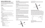
30 paces (90 feet/28 meters)
1. With the model restrained on the ground, stand 30 paces (approx. 90 feet/28 meters) away
from the model.
2. Face the model with the transmitter in your normal flying position and place your
transmitter into range check mode.
3. You should have total control of the model with the button depressed at 30 paces (90
feet/28 meters).
4. If control issues exist, call the Product Support Team in the U.S. at 1-877-504-0233 for
further assistance. In the UK or Germany use one of the following contacts.
European Union: +
44 (0) 1279 641 097 (United Kingdom)
or email [email protected]
+49 4121 46199 66 (Germany)
or email [email protected]
Advanced Range Testing
For sophisticated models that have significant conductive material in them, the advanced range
test using a flight log is recommended. The advanced range check will confirm that the internal
and remote receivers are operating optimally and that the installation (position of the receivers)
is optimized for the specific aircraft. This Advanced Range Check allows the RF performance of
each receiver to be evaluated and to optimize the locations of the remote receiver.
How QuickConnect™ With Brownout Detection Works
• When the receiver voltage drops below 3.5 volts the system drops out (ceases to operate).
• When power is restored the receiver immediately attempts to reconnect to the last two
frequencies that it was connected to.
• If the two frequencies are present (the transmitter was left on) the system reconnects
typically within one second.
Advanced Range Test
1 P lug a Flight Log (SPM9540 - optional) into the Batt/Data port on the AR7600 and turn on
the system (Tx and Rx).
2. Advance the Flight Log until F-frame losses are displayed by pressing the button on the
Flight Log.
3. Have a helper hold your aircraft while observing the Flight Log data.
4. Standing 30 paces away from the model, face the model with the transmitter in your
normal flying position and put your transmitter into range test mode. This causes reduced
power output from the transmitter.
5. H
ave your helper position the model in various orientations (nose up, nose down, nose
toward the Tx, nose away from the Tx, etc.) while your helper watches the Flight Log noting
any correlation between the aircraft’s orientation and frame losses. Do this for 1 minute.
The timer on the transmitter can be used here.
QuickConnect with Brownout Detection is designed to allow you to fly safely through most short
duration power interruptions, however, the root cause of these interruptions must be corrected
before the next flight to prevent catastrophic safety issues.
Receiver Power System Requirements
Inadequate power systems that are unable to provide the necessary minimum voltage to the
receiver during flight have become the number one cause of in-flight failures. Some of the
power system components that affect the ability to properly deliver adequate power include:
• Receiver battery pack (number of cells, capacity, cell type, state of charge)
• The ESC’s capability to deliver current to the receiver in electric aircraft
• The switch harness, battery leads, servo leads, regulators etc.
The AR7600 has a minimum operational voltage of 3.5 volts; it is highly recommended the
power system be tested per the guidelines below and in the Flight Log section.
Recommended Power System Test Guidelines
If a questionable power system is being used (e.g. small or old battery, ESC that may not have
a BEC that will support high-current draw, etc.), it is recommended that a voltmeter be used to
perform the following test.
Note: The Hangar 9 Digital Servo & Rx Current Meter (HAN172) or the Spektrum Flight Log
(SPM9540) are the perfect tools to perform the test below.
Plug the voltmeter into an open channel port in the receiver and with the system on, load the
control surfaces (apply pressure with your hand) while monitoring the voltage at the receiver.
The voltage should remain above 4.8 volts even when all servos are heavily loaded.
Note: The latest generations of Nickel-Metal Hydride batteries incorporate a new chemistry
mandated to be more environmentally friendly. These batteries when charged with peak
detection fast chargers have tendencies to false peak (not fully charge) repeatedly. These
include all brands of NiMH batteries. If using NiMH packs, be especially cautious when
charging, making absolutely sure that the battery is fully charged. It is recommended to
use a charger that can display total charge capacity. Note the number of mAh put into a
discharged pack to verify it has been charged to full capacity.
QuickConnect With Brownout Detection
Your AR7600 features QuickConnect with Brownout Detection.
• Should an interruption of power occur (brownout), the system will reconnect immediately when
power is restored (QuickConnect).
• The LED on the receiver will flash slowly indicating a power interruption (brownout) has occurred.
• Brownouts can be caused by an inadequate power supply (weak battery or regulator), a loose
connector, a bad switch, an inadequate BEC when using an electronic speed controller, etc.
• Brownouts occur when the receiver voltage drops below 3.5 volts thus interrupting control as the
servos and receiver require a minimum of 3.5 volts to operate.
Note: If a brownout occurs in flight it is vital that the cause of the brownout be determined
and corrected.
Flight Log (SPM9540 Optional)
The Flight Log is compatible with the AR7600. The Flight Log displays overall RF link
performance as well as the individual internal and external receiver link data. Additionally it
displays receiver voltage.
Using the Flight Log
After a flight and before turning off the receiver or transmitter, plug the Flight Log into the Data
port on the AR7600. The screen will automatically display voltage e.g. 6v2= 6.2 volts.
Note: When the voltage reaches 4.8 volts or less, the screen will flash indicating low voltage.
Press the button to display the following information:
A - Antenna fades on the internal antenna
B – Not used
L – Antenna fades on the external antenna
R – Not used
F - Frame loss
H - Holds
Antenna fades—represents the loss of a bit of information on that specific antenna.
Typically it’s normal to have as many as 50 to 100 antenna fades during a flight. If any single
antenna experiences over 500 fades in a single flight, the antenna should be repositioned in the
aircraft to optimize the RF link.
Frame loss—represents simultaneous antenna fades on all attached receivers. If the RF link
is performing optimally, frame losses per flight should be less than 20. A hold occurs when 45
consecutive frame losses occur. This takes about one second. If a hold occurs during a flight, it’s
important to evaluate the system, moving the antennas to different locations and/or checking to
be sure the transmitter and receivers are all working correctly.
Note: A servo extension can be used to allow the Flight Log to be plugged in more
conveniently. On some models, the Flight Log can be plugged in, attached and left on
the model using double-sided tape. Mounting the Flight Log conveniently to the side
frame is common with helicopters.
ModelMatch
Some Spektrum and JR transmitters offer a patent pending feature called ModelMatch.
ModelMatch prevents the possibility of operating a model using the wrong model memory,
potentially preventing a crash. With ModelMatch each model memory has its own unique code
(GUID) and during the binding process the code is programmed into the receiver. Later, when the
system is turned on, the receiver will only connect to the transmitter if the corresponding model
memory is programmed on screen.
Note: If at any time you turn on the system and it fails to connect, check to be sure the
correct model memory is selected in the transmitter. Please note that the Spektrum
Aircraft Modules do not have ModelMatch.