1
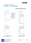
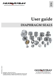
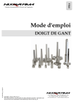
ENG
Industrial instrumentation for Pressure and Temperature
User guide
MI-TW/11/ENG rev.0
THERMOWELL
Copyright Nuova Fima S.p.A.
All rights reserved. Any part of this publication should not be
reproduced without a written Nuova Fima’s S.p.A. approval
Via C. Battisti, 59/61 – 28045 INVORIO (No) – Italy
Tel. +39 0322 253200 – Fax +39 0322 253232
www.nuovafima.com – e-mail: [email protected]
User guide
THERMOWELL
Index
1. IMPORTANT INFORMATION________________________________________________________________3
1.1 INTENDED USE _____________________________________________________________________________3
2. INSTALLATION ____________________________________________________________________________3
2.1 SCREW-FITTING THERMOWELLS ________________________________________________________________5
2.2 WELD-FITTING THERMOWELLS _________________________________________________________________5
2.3 THERMOWELL WITH FLANGE CONNECTION ________________________________________________________5
3. USE LIMITS ________________________________________________________________________________6
3.1 VIBRATION RUPTURE (RESONANCE) _____________________________________________________________6
3.2 FATIGUE RUPTURE __________________________________________________________________________6
3.3 OVERPRESSURE RUPTURE _____________________________________________________________________7
3.4 CORROSION RUPTURE ________________________________________________________________________7
3.5 STATIC-BENDING RUPTURE ____________________________________________________________________7
3.6 OVERTEMPERATURE RUPTURE _________________________________________________________________7
4. WRONG APPLICATION _____________________________________________________________________7
4.1 MODIFICATION OF THE INSTALLATION POINT ______________________________________________________7
4.2 INSTALLATION WITH INTERFERENCE COLLAR ______________________________________________________7
5. MAINTENANCE AND CLEANING ____________________________________________________________7
5.1 MAINTENANCE _____________________________________________________________________________7
5.2 CLEANING_________________________________________________________________________________7
6. DISMOUNTING AND DISPOSAL _____________________________________________________________7
6.1 DISMOUNTING _____________________________________________________________________________8
6.2 DISPOSAL _________________________________________________________________________________8
2
NUOVA FIMA - Industrial instrumentation for Pressure and Temperature
User guide
THERMOWELL
1. Important information
The instrument described in this manual has been designed and produced in conformity to the following
standards:
ASME PTC 19.3 TW 2010, ASME B16.5 e ASME B31.1. All components are subject to stringent quality and
traceability controls. The quality management system is certified according to the ISO 9001 standard. This
manual contains important information on handling and the installing the instrument in safe conditions.
Therefore it is highly recommended to read carefully the following instructions prior to beginning any work.
This instrument operates in safe conditions if correctly selected and installed in the system and when these operating
instructions and the maintenance procedures that are established by the manufacturer are respected.
The staff charged with the selection, installation and maintenance of the instrument must be able to recognize the
conditions that may negatively affect the instrument's ability to work and which may lead to premature breakage. The
staff must therefore be technically qualified and properly trained, and must carry out the procedures called for in the
plant regulations.
Nuova Fima offers a design and engineering service for the right matching of the thermowell
to the system where it is installed.
In case of dynamic process Nuova Fima ALWAYS recommends and offers the possibility to examin the
thermowells according to ASME PTC 19.3 TW 2010.
-
-
The manufacturer disclaims all responsibility in case of damages caused by the improper
use of the product and by the non-respect of the instructions reported in this manual.
Follow carefully the specific safety rules in case of measuring oxygen pressure, acetylene,
inflammable or toxic gas or liquids.
Disconnect the instruments only after depressurization of the system.
The process fluids residuals in the disassembled instruments could affect people, the
environment and the system. It is highly recommended to take proper precautions.
Before installation be sure that the right instrument has been selected following the
working conditions and in particular the range, the working temperature and the
compatibility between the material used and the process fluid.
This manual does not concern the instruments conforming to standard 94/9/CE (ATEX).
The product warranty is no longer valid in case of non-authorized modifications and of
wrong use of the product.
The user is totally responsible for the instrument installation and maintenance.
In order to verify the working and manufacturing features of the instruments read
the catalogue sheets in the most up-dated edition available on.line on www.nuovafima.com
1.1 Intended use
Thermowells are use to protect bulbs from the effects of corrosion and process fluid flow, due to the high speed at
which the process fluid flows, and to enable the thermometer to be interchanged, recalibrated, or replaced, without
disturbing the process
2. Installation
Before installation verify the chemical compatibility between the thermowell selected and the process medium and its
endurance to mechanical stress due to the medium itself.
The non-observance of these recommendations can result in serious injuries and damages to the system.
NUOVA FIMA - Industrial instrumentation for Pressure and Temperature
3
User guide
THERMOWELL
The instrument has to be compatible with respect to the measurement range and the system conditions. During
installation thermowells should not be subjected to thermal shocks or mechanical impacts.
Insert the thermowell into the process adapter without forcing or damaging it. The thermowell must not be bent or
altered during mounting. It is recommended to mount the temperature measuring instrument into the thermowell
using a suitable sealing material in order to avoid humidity ingress.
Generally the tip of the thermowell should be placed in the middle third of the pipe, though the position may differ in
special cases.
It must be ensured that the measuring element sensing part, (thermocouples, bi-metal or inert gas thermometers ) is
completely exposed to the medium.
If as a result of a small pipe diameter, this cannot be ensured, a pipe expansion can be inserted around the measuring
point.
Three mounting positions in the system are possible. These are independent from the process connection type:
1. Right-angled position with respect to the flow
2. Tilted position with respect to the flow:
a. Upstream
4
b. Downstream
NUOVA FIMA - Industrial instrumentation for Pressure and Temperature
User guide
THERMOWELL
The insertion length and the diameter of the thermowell are dependent on the process conditions especially on the
flow rate of the measured medium.
2.1 Screw-fitting thermowells
When using a parallel threads, a suitable seal should be used when mounting. Tapered threads can be sealed directly
on the thread. For the correct tightness it is recommended to apply a PTFE tape on the male thread compatible with
the process temperature (200C°max).
This is not allowed on tapered threads.
2.2 Weld-fitting thermowells
Weld-in thermowells can be mounted into the process directly (pipe or vessel wall) or by using a welded socket. Make
sure that the weld seam is clean and that suitable equipment is used. If necessary heat-treat the weld seams.
2.3 Thermowell with flange connection
The flange dimensions of the thermowell must match those of the mating flange on the process side. The seals used
must be suitable to the process and chemically compatible..
In case of process high flow rate the correct tightening torques and suitable tools (spanners) should be used for
installation. The use of spanners is recommended in order to resist the vibrations and bending stress caused by the
process medium flow rate.
ANTI-VIBRATION COLLAR
"NOZZLE"
The interception collar should match with the inner diameter of the nozzle for the proper operation of it. The collar
shifts the thermowell constraint point towards the stem reducing the way the thermowell portion is affected by the
flow rate.
According to ASME PTC 19.3 TW 2010 standard the interference collar thermowells
are not recommended and they are not included in the above mentioned directive.
NUOVA FIMA ensures a proper endurance of these instruments only if correctly installed. That is a lightly forced
coupling between the outside diameter of the collar and the inner diameter has to be applied.
The necessary procedure to obtain a correct coupling is described as follows:
Design:
1) The outside diameter of the collar should be more than 0,15mm at least with respect to the inner bore diameter
where the thermowell is installed.
2) Install the interference collar as close as possible to the nozzle near the pipe.
NUOVA FIMA - Industrial instrumentation for Pressure and Temperature
5
User guide
THERMOWELL
Interference collar thermowell installation
WARNING: A lightly forced coupling between the collar and the nozzle bore is essential for a correct
operation.
On the contrary if the thermowell does not match perfectly the correct function of the instrument is not
possible.
1) Gradually install the thermowell into the nozzle. If the thermowell fits correctly, no other operation is necessary. If
it doesn’t, rotate the thermowell without too much force until it reaches the expected position.
2) If the thermowell does not fit in remove it carefully, gradually reducing the outer collar diameter by decreasing it
by 0,05mm at a time and then verify the nozzle fitting manually. Repeat these operations until you obtain a lightly
forced manual coupling of the thermowell in the nozzle. If the collar is hit by the interference only partially, then
proceed to the diameter reduction only as far as that part is concerned.
ATTENTION: the collar just reduces the vibrations effects caused by the process medium. Vibrations in the
pipe and/or on the nozzle plus those produced by the process medium could affect the integrity of the
thermowell
3. Use limits
The main thermowell failure cases are listed below.
In order to find out correctly the instrument’s working limits contact the Nuova Fima technical assistance department
which will take care to calculate the correct thermowell dimensions according to ASME PTC 19.3 TW 2010.
The tests which have been carried out are:
a) Resonance test
b) Fatigue test
c) Bending test
d) Maximum pressure test
e) Minimum temperature test
3.1 Vibration rupture (Resonance)
In case of a dynamic process in which the process medium flow rate is high the thermowell could vibrate. This is
because of oscillations that can subsequently develop in the process medium caused by the turbulent nature of the
vortex. The vortex which can be detached from the fluid flow surrounding the thermowell.
When the vibration frequency of the fluid movement coincides with the natural one of the thermowell we can say that
the thermowell is in resonance. At this state the movement range due to bending increases seriously as well as the
bending stress causing a tension level to the thermowell which is higher than the maximum limit allowed for the
material.
In this way the thermowell is damaged where tensions are higher that is in the thermowell constraint
point. In this case there is the risk of leakage which could affect the outer parts of the process.
It is necessary to install the thermowell far from the resonance area, or when the process type does not allow that,
replace it with a thermowell designed with a shorter immersion length or an antivibration collar.
3.2 Fatigue rupture
In case of dynamic process the thermowell is subject to stress.In fact the dynamic properties of the medium make the
thermowell oclillate cyclically causing a mechanical stress to it. After repeated cycles the thermowell could break
because of the widening of a crack which usually create nearby the welding between the flange and the thermowell
body in the constraint point where tension due to fatigue (and bending) is higher.
So it is necessary to establish if the resulting dynamic tensions are lower than those supported by the material
maximum fatigue limit. If they are not, replace the thermowell installing one whose dimensions can support the
current dynamic stress.
6
NUOVA FIMA - Industrial instrumentation for Pressure and Temperature
User guide
THERMOWELL
3.3 Overpressure rupture
In case of pressure peak due to a system malfunction the thermowell could be subject to a higher pressure value
compared to the maximum tolerable limit. In this case the thermowell hydrostatic tightness cannot be guaranteed. If
the thermowell is not able to tolerate such a pressure value. It is then necessary to replace it with another one whose
dimensions are suitable to the oscilltations produced by the maximum current pressure.
3.4 Corrosion rupture
In case of particularly agressive process medium the thermowell material and welded parts could be eroded. That is
why it is necessary to choose the most suitable material matched to the process medium in order to ensure a properly
functioning thermowell.
3.5 Static-bending rupture
If the thermowell is subject to a fluid flow it tends to bend depending on the flow rate velocity. Threrefore it is
necesssary to prevent this by choosing the right thermowell dimensions.
3.6 Overtemperature rupture
In case the process temperature is higher than the maximum allowed temperature with respect to the thermowell
material, the established security standards are no longer ensured; the mechanical thermowell properties slightly
decrease when the temperature exceeds the maximum limit. Therefore it is necessary to select a material suitable to
the process temperature range in order to prevent any damage to the system.
4. Wrong application
In case of damage caused by using the product contrary to its intended use the guarantee will be no longer valid.
Below is a list of the main uses incorrect.
4.1 Modification of the installation point
Do not use the thermowell in a different system area other than that specified in the order.By modifying the process
characteristics of the thermowell the working range could be reduced or even the thermowell could be rendered
unusable.
In case of any system characteristics modification the thermowell verification according to ASME PTC 19.3
TW 2010 won’t be valid anymore.
4.2 Installation with interference collar
In case during the thermowell installation an interference collar is expected to be used in order to avoid any slack
between the nozzle diameter and the collar itself. For further information about the correct installation of the
interference collars refer to paragraph 2.3 of this use instructions manual.
5. Maintenance and cleaning
5.1 Maintenance
Generally thermowells are maintenance-free. A visual check at regular intervals of the thermowell is recommended in
order to detect leaks or damages. Make sure that the seal is in perfect condition. Repairs should only be carried out by
the manufacturer or, following prior consultation, by correspondingly qualified skilled personnel.
5.2 Cleaning
Wash and clean the dismounted instrument before returning it, in order to protect staff and the environment from
exposure to residual media.
6. Dismounting and disposal
Residual media on dismounted thermowells can result in a risk to persons, the environment and equipment. Take
sufficient precautionary measures.
NUOVA FIMA - Industrial instrumentation for Pressure and Temperature
7
User guide
THERMOWELL
6.1 Dismounting
Let the instrument cool down sufficiently before dismounting it. When dismounting it, there is a risk
that dangerously hot pressure media may escape.
Only disconnect thermowells once the system is depressurised.
6.2 Disposal
Incorrect disposal can put the environment at risk. Dispose of instruments, components and packaging materials in an
environmentally compatible way and in accordance with the country-specific waste disposal regulations.
8
NUOVA FIMA - Industrial instrumentation for Pressure and Temperature