1
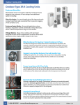
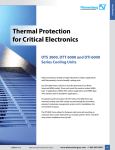
ELECTRO-TECHNOLOGY FOR INDUSTRY DTS 3000 Series Cooling Units Installation, Operation and Service Manual Safety for man, machine and the environment® TABLE OF CONTENTS SECTION 1: HOW TO USE THIS MANUAL...........1 SECTION 2: RECEIVING INSPECTION.................2 2.1 Unpacking............................................................ 2 2.2 Included Items.................................................... 2 2.3 Review of ID Plate................................................ 2 SECTION 3: HANDLING.......................................3 3.1 Transporting........................................................ 3 3.2 Storage................................................................. 3 SECTION 4: INSTALLATION.................................3 4.1 Pre-installation testing....................................... 3 4.2 Installation onto the electrical panel................. 3 4.3 Power connection................................................ 4 4.4 Door contact........................................................ 5 SECTION 5: OPERATING CONDITIONS...............5 5.1 Requirements...................................................... 5 5.3 Condensation Consideration.............................. 6 SECTION 6: UNIT START-UP................................7 6.1 General................................................................. 7 6.2 Fault indicator / LED Display............................... 7 6.3 Test Mode / Start-up............................................ 8 6.4 Door Contact........................................................ 8 6.5 Setting the Operating Parameters..................... 8 SECTION 7: MAINTENANCE................................9 7.1 General Maintenance.......................................... 9 7.2 Cleaning............................................................... 9 SECTION 8: TROUBLESHOOTING.................... 10 8.1 Verifying Normal Function...............................10 8.2 Fault Condition..................................................10 8.3 Error Codes.........................................................11 SECTION 9: DESIGN DATA................................ 12 9.1 SCCR Determination..........................................12 SECTION 10: WARRANTY INFORMATION....... 14 DTS Series Cooling Units SECTION 1: HOW TO USE THIS MANUAL This manual contains information on the installation and operation of DTS 3000 Series bolt-on cooling units intended to be door and side mounted on electrical panels. Conventions used: Hint: A hint contains additional information on the action or instruction being described WA R N I N G ! If the information following this is not strictly followed there is a danger to health or life. WA R N I N G ! If the information following this is not strictly followed there is a danger to health or life due to electrical shock. The technical data specific to each cooling unit including installation connections and operational data are contained on a separate data sheet. 1 SECTION 2: RECEIVING INSPECTION 2.2 Included Items The following items should be included: Cooling unit Mounting cutout Manual Technical Data Sheet 2.1 Unpacking Prior to and during unpacking the cooling unit, visually inspect it to determine if any damage has occurred during shipping. Make sure that it does not contain any loose components. Before discarding any packaging materials: Look for loose parts, dented or scratched panels or fluids. DTS 3000 Series accessory pack typically includes: • Sealing strips • Threaded mounting studs • Mounting bolts, nuts and washers • Condensate hose • Door contact connector/jumper If any damage is noted it shall be reported immediately to the delivering carrier and a claim should be filed with them. Pfannenberg cannot accept responsibility for freight damage that may occur; we will assist you in any way possible if the need arises to file a claim. 2.3 Review of ID Plate The ID plate is located on the left side of the cooling unit. The technical data specific to the cooling unit is located on the ID plate as shown below. In case of a warranty claim, the following information is required: exact details of the fault (including photographs, if possible), the cooling unit part number and serial number are required. WA R N I N G ! Burrs caused by production may be present on the metal edges of the cooling unit. Always wear protective gloves when carrying out installation or maintenance work. Cooling Part # Frequency Nominal Voltage Nominal Current Power Consumption Serial # Design Pressure Refrigerant Charge Cooling Capacity Heating Capacity Environmental Conditions Fusing 2 DTS Series Cooling Units SECTION 3: HANDLING SECTION 4: INSTALLATION 3.1 Transporting The cooling unit shall only be moved in the fully assembled, upright condition. 4.1 Pre-installation testing Before mounting the cooling unit to the electrical panel enclosure it should be tested to verify function. If the cooling unit is being shipped with an electrical panel enclosure it shall be packed separately from the electrical enclosure. 4.2 Installation onto the electrical panel Before connecting the cooling unit to the power supply, verify that the following are correct. Voltage must be within ± 10% of the value listed on the ID plate. WA R N I N G ! If for any reason the cooling unit has been placed in any position other than fully upright it shall be placed in a vertical position for a minimum of 1 hour prior to starting the unit. If this is not done the compressor may be drained of oil. Operation of the compressor without proper oil fill may cause permanent damage to the cooling unit and void the warranty. 3.2 Storage The cooling unit shall not be exposed to temperatures exceeding +70ºC. Store the unit fully assembled in the fully upright condition. WA R N I N G ! Failure to observe these requirements will void the warranty. Voltage frequency must be within ± 3 Hz of the value listed on the ID plate Ambient temperature must be below +55ºC (for options see “setting the operating parameters” section) Place the drilling template supplied with the cooling unit onto the applicable mounting surface of the electrical panel enclosure. WA R N I N G ! Metal chips from drilling and cutting the openings may damage the electrical panel enclosure. Take precautions required to prevent chips and debris from getting into the enclosure. WA R N I N G ! Watch out for sharp edges created when drilling and/or cutting the enclosure. Drill holes in the electrical panel enclosure to match the unit and cut out air flow openings. Remove the cooling unit cover for handling during installation by removing the cover mounting screws. Install the two supplied stud bolts (in the accessory pack) into the top two mounting hole locations of the cooling unit. WA R N I N G ! Please note the information on the “Thread Reach for Set Screw” label attached to the cooling unit. If the noted installed thread depth is exceeded the cooling unit may be damaged. Install the cooling unit mounting insulation strips (in 3 the accessory pack) to the cooling unit as noted on the individual cooling unit information sheet. Make sure that the insulation strips are correctly attached and placed correctly on the cooling unit. The correct fitting and location of the insulation strips is required for the proper operation of the cooling unit. Attach the cooling unit to the electrical panel enclosure by use of the stud bolts inserted as described above. WA R N I N G ! Do not move the cooling unit by the piping. Doing so will damage the cooling unit and void the warranty. required, shall only be carried out by authorized, trained electricians. WA R N I N G ! The cooling unit may be damaged due to compressor rotating in the incorrect direction. On three phase connection (400V/460V) units the power supply connections are phase sensitive. Make sure that the power connections are correct or the cooling unit will not operate properly. Power supply connection All units are provided with either a molded cord or permanent connection internal to the unit. permanent connection must be secured to the cooling unit by means of a cable strain relief. The cooling unit is then completely attached to the electrical panel enclosure from inside the enclosure by use of the screws and washers supplied in the accessory pack. Tighten the fasteners until the cooling unit insulation strips are compressed to a thickness of 2 mm (approx. .080”) Install the condensate drainage hose to the drain located in the cooling unit base. Reinstall the cover using the original mounting screws. 4.3 Power connection WA R N I N G ! Make sure that the main power supply to the cooling unit is turned off while making the power connections. The cooling unit power supply shall be fused as indicated on the unit ID plate by means of a series connected power line connection. A temperature control can not be connected in series with the cooling unit power supply. Both the main power supply voltage and frequency shall correspond to the nominal values shown on the cooling unit ID plate. WA R N I N G ! The cooling unit may be damaged if the supply voltage is too high. This refers to cooling units with (460V / 400V) multiphase connections. All power connections and / or repairs, if or when 4 DTS Series Cooling Units As an option, the control voltage can be adjusted to match the main power supply. Internal to the unit, a voltage jumper is provided to adjust the transformers incoming voltage. See technical data sheet included with cooling unit. Connect the main power supply to the cooling unit as indicated by the label located on the cooling unit and on the individual cooling unit data sheet. WA R N I N G ! During installation, service technician must verify and mark voltage as connected on service cover warning sticker. Terminal Connections: 4.4 Door contact To avoid an increased production of condensate and for safety reasons a door limit switch should be connected to the terminals provided. The power supplied to these terminals from the cooling unit is low voltage (<20V, 20mA). WA R N I N G ! No external voltage may be applied to the door contact circuit or damage to the cooling unit may result. In order to prevent any interference from outside signals, it is recommended that a shielded cable with a twisted pair leads be used for the connection. The cable shielding can be connected on one side to the PE (ground) connection point provided on the cooling unit. If the use of a shielded cable is not possible, the cable that is used must not be routed in the immediate vicinity of potential sources of interference such as power supply lines , components with a relatively high electromagnetic emission (EMI), etc. SECTION 5: OPERATING CONDITIONS 5.1 Requirements Before connecting the cooling unit to the power supply, verify that the following are correct. Voltage must be within ± 10% of the value listed on the ID plate. Voltage frequency must be within ± 3 Hz of the value listed on the ID plate Ambient temperature must be below +55ºC (for options see Section 6.5) If it ever becomes necessary for servicing, use only the refrigerant specified on the ID plate and genuine spare parts only or damage to the cooling unit may result. Before mounting, make sure that the cooling unit will have proper ventilation for operation. The cooling unit must have at least 200mm of clearance between it and any other surface. Make sure that the airflow inside of the electrical panel enclosure is not restricted by internal components. Enclosure Cooling Unit 8” (200 mm) Wall If no door contact switch is used, the connecting terminals must be jumpered for the cooling unit to operate. Centralized fault indicator option To connect the fault signal line there are two connection terminals available (see the connecting diagram on the label of the individual cooling unit). The signal of a fault in the cooling unit is displayed by the breaking of a potential-free contact. WA R N I N G ! These connection points may be connected to a live electrical line with a maximum of 230V, 2 A 5 WA R N I N G ! If the cooling unit is being mounted on the door of the electrical panel enclosure, it must be confirmed that the door hinges can support the additional weight of the cooling unit and that the electrical panel enclosure is securely fastened so that the panel enclosure will not topple over. enclosure and pushes it through the evaporator (4) and back into the electrical panel enclosure at a lower temperature. 5.2 Theory of Operation ∞ ∞ The cooling unit is electronically controlled. To accomplish this a temperature sensor monitors the temperature inside the electrical panel enclosure and regulates the function of the cooling unit. The refrigerants used in the cooling unit are noncombustible and are minimally detrimental to the atmosphere. 1 Compressor 2 Heat exchanger (condenser) 3 Expansion valve/ capillary line 4 Heat exchanger (evaporator) 5 fan, exterior circulation 6 fan, inner circulation 7 Electronic control system with temperature sensor The compressor (1) compresses the refrigerant until it becomes a high pressure gas. During the compression process, the temperature of the refrigerant gas increases. As the refrigerant in the form of a high pressure, high temperature gas flows through the condenser (2) the refrigerant cools and condenses as the heat is dissipated to the ambient (outside of the electrical panel) air. This is accomplished by the condenser fan (5) pulling in ambient air into the housing and then pushes the ambient air through the fin and coils of the condenser (2) and back out of the housing and into the ambient environment at a higher temperature. 5.3 Condensation Consideration During operation, the moisture in the air inside of the electrical panel enclosure condenses on the fins of the evaporator and is collected as condensate. In order to avoid any damage to the electrical panel enclosure contents or to the cooling unit, the condensate must be removed from the cooling unit. The condensate is removed as follows: The condensate drains into a condensate tray located at the bottom of the cooling unit and is evaporated into the ambient air by means of an electrical heating element. The free discharge of any accumulated condensate must be provided for to ensure trouble-free operation of the cooling unit. The PTC-heater starts heating immediately on the application of power to the cooling unit. The PTCheater is self-controlled and it’s temperature will vary depending on the level of condensate in the condensate tray. As the now liquid refrigerant passes through the expansion valve (3) the pressure drops and the refrigerant becomes a liquid / gas mixture. As the refrigerant in the form of a liquid / gas passes through the evaporator (4) it absorbs the heat from air in the electrical panel enclosure while also dehumidifying it. This process lowers the temperature of the air in the electrical panel enclosure This is accomplished by the evaporator fan (6) pulling in the hot air from the electrical panel 6 DTS Series Cooling Units SECTION 6: UNIT START-UP WA R N I N G ! HOT SURFACE Even if there is no condensate in the condensate tray the PTC-heater will be on at a low output. In the case of excessive condensate drainage the condensate tray located at the bottom of the cooling unit may fill with condensate which is then drained away by means of a hose connection. WA R N I N G ! If there is excessive condensate formation during normal operation, check the electrical panel enclosure seals. We recommend that a door contact switch be installed to turn off the cooling unit when the door to the electrical panel enclosure is opened in order to prevent excessive condensate formation. 6.1 General The cooling unit is equipped with an electronic control system. The temperature of the air pulled in from the electrical panel enclosure into the cooling unit is measured by a temperature sensor. WA R N I N G ! Ambient conditions and temperatures in the electrical panel must be in accordance with the values indicated in the cooling unit information sheet. WA R N I N G ! Unit must be operated with the cover installed. Unit can not cool properly when cover is not in place. Immediately after the main power is turned on for the cooling unit, the unit goes into its start-up / test mode. 6.2 Fault indicator / LED Display The cooling unit has an operational display in the form of an LED located either on the rear of the cooling unit or on the external hood of the cooling unit. If the indicator light remains on when the power supply is turned on, it means that the cooling unit is in its normal operating mode. If a fault is detected or if the cooling unit is in its start-up / test mode, the LED will flash in a fault code that can be used to help diagnose the problem. 7 6.3 Test Mode / Start-up The start-up / test mode is activated whenever the unit has had power removed and re-applied. While in this mode the cooling unit operates independently from the ambient conditions when the door contact is closed. The cooling unit runs through a start up sequence that takes approximately 30 seconds to accomplish. The start-up mode is also activated whenever the door limit switch is closed. Modus Start-up Mode Time Curve t = 0s - < 30s t = 30s t = 32s Characteristics No function. Internal fan start up. External fan and compressor start up. Flashing sequence of the status indicator: "off-dark-light-dark-off". Fault signal contact is closed. Self Test during Start t > 34s - 64s The location of the DIP switch is on the cooling unit control board as shown on its circuit diagram. The coding options are represented on the circuit diagram. The circuit diagram and / or display image are to be found on the inside of the service cover of the cooling unit or on the individual cooling unit information sheet. See the cooling unit information sheet for additional details. WA R N I N G ! Changes to the operating parameters of the cooling units should only be made by authorized personnel. Compressor and fans remains in operation during the period. Flashing sequence of the status indicator: "off-dark-light-off". Fault signal contact is open. Should a fault arise during the test mode, the unit goes into the fault mode and the status indicator lights up according to the fault state (See Section 8.1) 6.4 Door Contact For safety reasons and to prevent an increased output of condensate, a door limit switch should be connected to the terminals provided on the cooling unit. (see the wiring diagram on the individual cooling unit or on the individual information sheet supplied with the cooling unit. With the switch in place, when the electrical panel enclosure door is opened (thereby opening the switch) all of the cooling unit motors are immediately turned off. When the electrical panel enclosure door is closed, the cooling unit start-up mode begins and is run through which ensures a restart-up of the cooling unit with a time lag. 6.5 Setting the Operating Parameters Various electrical panel enclosure temperatures as well as the limit temperatures can be selected by means of a DIP switch on individual cooling units. 8 DTS Series Cooling Units SECTION 7: MAINTENANCE 7.1 General Maintenance WA R N I N G ! Disconnect the cooling unit from the power supply before any cleaning or maintenance. The cooling unit is largely maintenance free. The cooling circuit is a maintenance free hermetically sealed system. It has been filled at the factory with the required refrigerant amount, checked for leakage and run through a series of functional tests before being shipped. The components around the external air circuit require periodic cleaning and maintenance depending on the environmental conditions. 7.2 Cleaning The cleaning intervals depend upon the relevant operating conditions. In particular, observe the following instructions: • Disconnect the cooling unit from the power supply • Remove the external cover • Clean the heat exchanger regularly using a soft brush or pressurized air • It is recommended that the condensate run off opening be checked regularly WA R N I N G ! Damage to the heat exchanger possible. Do not use any sharp or pointed object to clean the condenser heat exchanger. The heat exchanger fins should not be bent, compressed or damaged in any way during the cleaning process. If the cooling units are provided with a filter, clean the filter mat regularly. The cleaning intervals or the intervals for replacement of the filter mat mainly depends upon environmental conditions (air quality.) You can rinse the filter mat using water heated to 40° C and commercially available mild detergent. It is possible to remove any dirt by knocking the mat slightly, vacuum cleaning it or blowing it out. 9 If the filter mat is oily or greasy, please replace. SECTION 8: TROUBLESHOOTING 8.1 Verifying Normal Function Environmental conditions may eliminate the need for cooling. If the door contact circuit (X54) is opened then closed the unit will perform it's test function. This will cause all the components to activate and the unit will provide cooling for a short time. (See below.) If cooling does not occur, please review the troubleshooting topics listed below. Modus Time Curve Characteristics Start-up Mode t = 0s - < 30s t = 30s t = 32s No function. Internal fan start up. External fan and compressor start up. Flashing sequence of the status indicator: "off-dark-light-dark-off". Fault signal contact is closed. Self Test during Start t > 34s - 64s Compressor and fans remains in operation during the period. Flashing sequence of the status indicator: "off-dark-light-off". Fault signal contact is open. Should a fault arise during the test mode, the unit goes into the fault mode and the status indicator lights up according to the fault state. NO DIP SWITCH CHANGES ARE REQUIRED. 8.2 Fault Condition If a fault occurs, check the following points first. If the fault is then not cleared, call an authorized specialist. Fault Unit fails to cool. Internal fan is running. Unit fails to cool sufficiently. Condensate accumulates in switch cabinet. Condensate fails to drain. Possible cause(s) Remedy Temperature setting is above ambient. Check temperature setting. Required cooling capacity exceeds capacity of unit. Check ambient temperature and internal load. Dirty filter or condenser. Clean condenser. Clean or replace filter. Lack of refrigerant. Call authorized technician. Check unit for leaks. Internal and external fans not working. Call authorized specialist. Check fan capacitors. Replace fans. Ensure proper electrical connections. Air not circulating properly inside the switch cabinet. Check enclosure and air circulation inside enclosure. Air intake and exhaust must be unimpeded by components. Exiting temperature is too low. Enclosure is not sufficiently sealed. Condensate drain is clogged Set cooling unit to a higher temperature setting. Close enclosure door and improve the seal in the enclosure. Clean condensate drainage. Condensate drainage hose must be angled downward without showing a bend. 10 DTS Series Cooling Units 8.3 Error Codes Unit Characteristics Technical Causes Fault Remedy Compressor: Internal Fan: External Fan: Status LED: Fault signal contact: ON ON ON flashing (seq. 3) open The test mode of the unit is active. This mode is left automatically at the latest after 60 s. The unit switches to test mode once after each new connection to the power supply. No remedy of fault necessary. Compressor: Internal Fan: External Fan: Status LED: Fault signal contact: OFF OFF OFF flashing (seq. 1) closed The input for the door limit switch is open - e.g. as a result of a switch cabinet door not closed or a bridge not set. Insert link, close door contact switch, or with an engaged door contact switch, close the door. Compressor: Internal Fan: External Fan: Status LED: Fault signal contact: OFF ON OFF flashing (seq. 2) open High pressure pressostat or motor protection switch has responded (overheating). Compressor switches on again automatically after the fault has been remedied (cooling) with a delay of 30 s. Clean filter mat or heat exchanger in the external circulation. Possibly check the power dissipation in the switch cabinet to the installed cooling capacity of the cooling unit. Compressor: Internal Fan: External Fan: Status LED: Fault signal contact: ON ON ON flashing (seq. 1) open The upper temperature limit (T L2) of the switch cabinet has been exceeded. Clean filter mat or heat exchanger in the external circulation. Possibly check the power dissipation in the switch cabinet to the installed cooling capacity of the cooling unit. **Sequence 1: (User Error) ***Sequence 2: (Unit Fault) ****Sequence 3: (Test/start-up mode) 11 SECTION 9: DESIGN DATA rating of the control panel. The link to spreadsheets provide guidance for industrial control panel manufacturers who purchase the discreet components and assemble combination motor controllers within their panels to achieve a combination short circuit rating that is higher than the lowest rated individual component. Please refer to the cooling unit individual technical data sheets for the following: Dimensional Data Mounting Cutout Circuit Diagrams 9.1 SCCR Determination Article 409 of the 2005 National Electric Code (NFPA 70) requires Industrial Control Panels (electrical panel enclosures) to be marked with a short circuit current rating. As specified in the National Electric Code, the Standard for Industrial Control Equipment, UL508A-2001, Supplement SB, provides an accepted method for determining the short circuit current (3) 15A Class CC Fuses Table 1 Room cooling units rated-Load Current, Amperage 3 Phase3 Single Phase3 110 - 120 V 100kA 9.9 Branch 200 - 208 V Using the technical data sheet and the information on the cooling unit ID plate, identify the full load current conditions for the appropriate voltage. The installation of the cooling unit should be calculated as a dedicated branch circuit for determining the SCCR value. All selections should be evaluated based on the current UL standards for UL508a. 220 - 240 V Marked 8.8 SCCR-5 kA 5.0 50 KA Peak Let-thru Current2 Max Fuse1 Ip x 103 Less 1000 15 50 KA 254 - 277 V 440 - 480 V 8.0 6.65 Less 1.8 16.0 5.4 16.1 34.0 8.9 18.6 8.1 17.0 --- --- --- --- 2000 30 50 KA --- --- --- --- --- --- --- --- Over 1.8 5000 15 50 KA 100 KA Max Fuse1 Ip x 103 200 KA Max Fuse1 Ip x 103 n/a n/a 15 100 KA n/a 30 100 KA 30 200 KA Maximum CC class Fuse size that can achieve this branch circuit SCCR value. Smalller values may be used and still achieve equal rating. 2 Circuit capacity amperes based on UL 484 table 52.1 3 Individual units running amperes can be obtained on each unit's technical data sheet. 1 1.5 HP Example 2: DTS 35xx 460V units has a 5KA IR value based on UL 484 table 52.1 (see Table 1) and the amp draw of the unit. If a 15amp Class CC current limiting feeder circuit is used in combination with the DTS35xx 460V unit, the maximum allowable Ipeak of the 15 amp Class CC fuse at an available RMS fault current of 200 kA is 1700 amps (figure 2). This value does not exceed the allowable Ipeak of this unit based on UL SCCR value of Table 52.1. Threrefore, the individual branch circuit SCCR value of this series combination can support 200 kA IR. (See figure 1.) Figure 2 12 DTS Series Cooling Units Figure 1 Option 3: UL 508a reference SB4.2 The combinations listed in the linked spreadsheets (www.ul.com/controlequipment/shortcircuit.html) may be applied in a manufacturer's Listed industrial control panel without further evaluation or specific documentation in the manufacturer's UL Procedure pages. (3) 15A Class CC Fuses 100kA Branch Marked SCCR-5 kA 1.5 HP Option 1: UL 508a reference SB4.2 According to UL508A Supplement SB, if a panel contains no current-limiting devices, its SCCR depends on the “weakest” or lowest rated component or combination within the panel. However, Supplement SB also states that if currentlimiting fuses are used in the feeder circuit, and if the highest instantaneous current reached during the first half cycle of a fault is less than or equal to the lowest rated SCCR in any branch circuit, the SCCR of the current limiting fuse can be applied to the combination. When the specified branch circuit protection related to the high fault short circuit current rating is a Class CC,G,J,L,RK1, RK5 or T fuse, a fuse of a different class is able to be used at the same high fault rating where the peak let through current and I2t of the new fuse is not greater than that of the specified fuse. Option 2: UL 508a reference SB4.3 An alternate method of achieving a high short circuit rating is by applying a power transformer with an isolated secondary winding, the short circuit current rating on the line side of the transformer shall be one of the following: For a power transformer rated not more than 10 kVA, and where the short circuit current rating of all components in the secondary circuit are not less than 5kA, the short circuit current rating of the primary overcurrent protective device is able to be assigned to the line side of the power transformer circuit. For a power transformer rated not more that 5kVA and a 120V maximum secondary voltage, and where the short circuit current rating of all components in the secondary circuit are not less than 2kA, the short circuit rating of the primary overcurrent protective device is able to be assigned to the line side of the power transformer circuit. 13 The spreadsheets cover the application of individual components, including a disconnecting means, an over current protective device, motor controller and motor overload protection, as a combination motor controller having specified ratings, including a short-circuit current rating (SCCR). Each of the individual components is Listed or Recognized to the requirements in the applicable component Standard. The specified ratings for the combination motor controller may be applied to the end-product equipment only when all of the specific components listed are provided in the end-product equipment and installed according to any applicable conditions of acceptability. Components other than those identified in the combination motor controller and connected in the power circuit of the combination motor controller will require additional evaluation. SECTION 10: WARRANTY INFORMATION (WARRANTY IS VALID FOR 1 YEAR) Warranty becomes null and void: In case of improper usage of the unit, noncompliance with operating conditions or nonobservance of instructions the warranty becomes null and void. If operated in rooms in which corrosives or acids are present in the atmosphere. In case of damage caused by contaminated or jammed air filters. If a non-authorized person interrupts the cooling circulation, modifies the unit or changes the serial number. In case of damage caused by transport or by accidents. For the exchange of parts by non-authorized companies. In order to maintain your warranty rights please observe the following when returning the unit. Enclose an exact description of the fault in the shipping package. Enclose proof of delivery (delivery note or copy of invoice). Return the unit together with all accessories; use the original packaging or packaging of equivalent quality, send the unit freight prepaid and covered by an adequate transport insurance. 14 ELECTRO-TECHNOLOGY FOR INDUSTRY Pfannenberg Incorporated 68 Ward Road, Lancaster, New York 14086 Phone: 716-685-6866 Fax: 716-681-1521 email: [email protected] www.pfannenbergusa.com Org 05/09 © 2009 Pfannenberg Incorporated