1
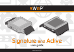
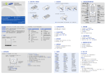
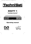
OPERATING INSTRUCTIONS
ELTRIP-R20
ELTRIP-R20f
Pilvitie 6
90620 Oulu
FINLAND
06/2012
p. +358-8-512 165
www.trippi.fi
[email protected]
Table of contents
1.TECHNICAL INFORMATION.................................................................................4
2.INSTRODUCTION....................................................................................................5
3.Installation of Eltrip-R20............................................................................................6
3.1.Installation location.............................................................................................6
3.2.Connection of cables...........................................................................................6
3.2.1. Using LEDs as change indicators................................................................7
3.3.Precautions!.........................................................................................................7
4.Setting up Eltrip-R20..................................................................................................8
4.1.Setting distance calculaton..................................................................................8
4.2.Settings................................................................................................................9
4.2.1.Brightness.....................................................................................................9
4.2.2.Distance unit.................................................................................................9
4.2.3.Speed unit.....................................................................................................9
4.2.4.RPM-Factor................................................................................................10
4.2.5.Language....................................................................................................10
4.3.Setting the time..................................................................................................10
4.4.Calibrating stopwatch........................................................................................10
4.5.Setting target average speed..............................................................................10
4.6.Calibrating fuel display (R20f-model only)......................................................10
5.Using Eltrip-R20.......................................................................................................12
5.1.Displays and counters........................................................................................12
5.1.1.Using displays............................................................................................12
5.1.2.Selecting display and counters...................................................................12
5.1.3.Clearing a counter.......................................................................................13
5.1.4.Setting the displays.....................................................................................13
5.2.Trip counters 1, 2 and 3.....................................................................................14
5.3.Clock..................................................................................................................14
5.4.Stopwatch..........................................................................................................14
5.4.1.Automatic starting of stopwatch.................................................................14
5.4.2.Stopwatch downcounting...........................................................................14
5.5.Speed.................................................................................................................15
5.6.Average speed....................................................................................................15
5.7.Time display of target average speed................................................................15
5.8.Arrival time.......................................................................................................15
5.9.RPM counter......................................................................................................15
5.10.Fuel (only R20F-model)..................................................................................16
5.11.Custom logo and turning display off...............................................................16
6.Usage of meter during race.......................................................................................17
6.1.Preparation.........................................................................................................17
6.2.Preparations before start....................................................................................17
6.3.After the race.....................................................................................................17
2
7.Problems?.................................................................................................................18
8.Declaration of Conformity........................................................................................19
9.Eltrip-R20 quick instructions....................................................................................20
3
1. TECHNICAL INFORMATION
KEYBOARD: 16 click-type buttons
COUNTERS:
• 3 trips; one with 1 metre and 2 with 10 metre resolution
• Clock; hours, minutes, seconds
• Speed with 0,1 km/h resolution
• Average speed with 0,1 km/h resolution
• Stopwatch with 1/100th second resolution
• Automatic start of stopwatch
• RPM counter
• Gear change indication based on RPM
• Fuel amount display (only R20f-model)
REGISTERS:
• Setting of imp/km
• Clock time
• Gear change thresholds (down/up)
• Fuel amount calibration
DISPLAY: Graphical display, 10mm or 5mm number height based on mode, can be
switched off
DIMENSIONS: 145x47x25mm (W x H x D)
WEIGHT: approx 150 g
OPERATING VOLTAGE: 10-30v
POWER CONSUMPTION:
• Display on approx. 100mA, Display off approx. 50mA
OPERATING TEMPERATURE: -30º - +60º C
FURE: max 400 mA
SENSOR: multiple options
4
2. INTRODUCTION
We congratulate you for choosing a reliable ELTRIP-meter.
This booklet will instruct you on how to install and use your new Eltrip-meter. Please
read this booklet carefully so you are familiar with installation, calibration and the
use of the meter. This allows you to gain maximum benefits from the meter.
If you have any technical problems with the meter, see instructions chapter 7. The the
problem persists, please contact our local representative for further instructions.
Although we trust that you are expert on many suspects, please do not attempt to
open or repair the meter by yourself, as the repair of electronics inside the meter
requires special tools and knowledge. Attempt to repair the meter by yourself may
seriously damage the meter and void the warranty. Installation and use against these
instructions will also void the warranty.
When your rally meter is at end of its road, please return it to us our our
local representative for recycling. Returning the meter is free for you. For
further instructions, please contact us.
5
3. INSTALLATION OF ELTRIP-R20
3.1. INSTALLATION LOCATION
Install the meter so that you can easily read and reach it. The meter should not affect
the use of vehicle's other controls or visibility outside the vehicle. Avoid place where
meter is in direct sunlight or in front of heating vents.
3.2. CONNECTION OF CABLES
Sensor is installed according to separate instructions.
We recommend that the meter is installed to continuous power.
DANGER! RISK OF FIRE!
If the main power switch of vehicle is connected to minus (-) lead of battery and
you wish to connect meter to continuous power, please contact the manufacturer
for further instructions.
Inside the meter the minus lead (-) and meter housing are connected together.
This connection may bypass main power switch and cause safety hazard.
Black wire: Connect to vehicle chassis (ground).
Red: Power supply +10 .. +30v, fused with fast max. 400mA fuse. Can be taken from
vehicle fuse box or other suitable location that does not interfere meter or other
circuits of vehicle.
White: Positive wire of sensor is connected to white wire, negative wire of sensor to
vehicle ground (black wire). If vehicle's own distance pulse is used, only the white
wire is connected. Some vehicles may require an adapter for connection. If ABS
sensor is used, an external divider is required.
Purple: Negative/Positive counting (reverse). If you wish to connect meter so that
distance counts backwards when vehicle is in reverse gear, connect this to reverse
light. If you do not need this functionality, connect this to vehicle ground.
Yellow: Display clear with external switch. If you wish to use external switch to reset
meter counter (for example foot switch), connect the switch between this wire and
vehicle ground. If not needed, leave unconnected.
Green: RPM measurement. Connect green wire to RPM sensor. If RPM sensor is not
used, leave unconnected.
6
Orange: Gear up-change indicator light. Connect a lamp between this wire and
vehicle ground if gear up-change indicator is used. NOTE: If you with to use LED, a
resistor is required.
Brown: Gear down-change indicator light. Connect a lamp between this wire and
vehicle ground if gear down-change indicator is used. NOTE: If you with to use
LED, a resistor is required.
Blue: (R20f) Fuel amount measurement. Use vehicle's original fuel sensor.
Depending on vehicle, extra electronics may be needed.
Red: +10..+30v DC, fused 400mA
Brown: change indication down
Orange: change indication up
White: speed pulse in
Green: RPM in
Purple: reverse
Yellow: external clear
Blue: Fuel in
Black: vehicle ground/chassis
3.2.1. USING LEDS AS CHANGE INDICATORS
If you wish to use LED as change indicator light, connect anode of LED to +12v and
cathode through a (approx) 600 ohm resistor to meter's signal wire. Without the
resistor the LED will be damaged or destroyed almost immediately.
3.3. PRECAUTIONS!
When welding the vehicle, disconnect the meter from battery. Although the meter is
protected from electrical interference normally present within a vehicle, the high
voltages present during the welding process may damage sensitive electrical
equipment.
Replace blown fuse only with similar fuse (max 400mA, fast) .
7
4. SETTING UP ELTRIP-R20
4.1. SETTING DISTANCE CALCULATON
After installation the correct distance calibration factor must be set to meter. This is
the number of impulses from the sensor that indicates one kilometre (or mile) of
travel. Calibration constant depends on vehicle, its tires and location of sensor.
Accuracy of the meter fully depends on the calibration factor, so be careful when
adjusting it. If the conditions change later (if, for example, vehicle tires are changed),
verify the measurement accuracy and if needed, adjust calibration constant. Make
note of calibration constant so it may ne verified later.
Before calibration verify that the distance unit that the meter is set to use matches the
distance unit you with to use. Change it if needed (see chapter 4.2.2 below).
If you know the calibration constant (number of pulses per kilometre or mile), set it
to meter as follows:
1. Press SET and 1 keys at same time (SET first). Meter enters calibration mode.
2. Use number keys to enter calibration factor (for example 3653).
3. CLR key can be used to correct number
4. Accept number by pressing OK or Accept
If you do not know the exact calibration factor, you can also set it up by driving a
kilometre-long test track by selecting Measure when in calibration setup display.
Measurement is done as follows:
1. Drive vehicle to known one-kilometre track
2. Select Measure. If at start of track there are pulses measured, you may clear the
counter by pressing CLR.
3. Drive through the measurement track.
4. Accept measurement by selecting Use.
5. If measurement track was shorter or longer than 1 kilometre (or 1 mile), alter
reading as shown in following table:
Track length
100 m (0,1 mi)
200 m (0,2 mi)
500 m (0,5 mi)
1000 m (1,0 mi)
2000 m (2,0 mi)
Factor
10 x measured number
5 x measured number
2 x measured number
1 x measured number
0,5 x measured number
For example: On a 200 metre long track a number of 215 is measured. A correction
factor is applied: 215 x 5 = 1075, which is then set as meter's calibration constant.
8
When calibration is done, verify accuracy of measurement by driving through the test
track by using normal distance counter 1. If the measured distance does not match the
track length, correct the calibration constant.
4.2. SETTINGS
Used measurement units, language and RPM correction factor are done in meter
settings. Settings mode is entered from normal operating mode as follows:
1. Press SET+1 together to enter calibration mode
2. Select Settings (key B)
Setting items are selected with Previous / Next and then changed with Select, or by
pressing directly the number key of the settings (for example 2 for Distance unit).
When finished, press CLR to exit settings.
Settings display
4.2.1.BRIGHTNESS
Display brightness can be adjusted in 4 steps from dim (suitable for night use) to
bright that can be seen even in bright daylight.
4.2.2.DISTANCE UNIT
The unit used to display measured distances can be selected from three possibilities:
kilometres (km), miles (mi) or metres (m). Note that when changing between metric
and imperial units meter must be recalibrated, as the meter is always calibrated to
used base unit – either kilometre or mile. When using metre display meter is also
calibrated to one kilometre distance.
4.2.3.SPEED UNIT
Speed unit cal be selected from three possibilitiers: kilometres per hour (km/h), miles
per hour (mi/h) or metres per second (m/s). When changing speed unit meter does not
need recalibration unless distance unit is also changed, and using mixed units is also
possible (for example distance in kilometres per hour and speed in miles per hour).
9
4.2.4.RPM-FACTOR
In order to RPM display to show correctly, correct factor must be selected. The factor
depends on method of measuring of the RPM and the engine. For example, if given
measurement point gives 1 impulse per two revolutions of engine, correct factor is 2.
4.2.5.LANGUAGE
The language is selectable between finnish and english.
4.3. SETTING THE TIME
Meter has internal clock which will keep correct time for approximately a week after
meter has been disconnected from power, so for short vehicle maintenance
procedures clock does not need to be re-set. Note that clock does not automatically
switch between normal and daylight savings time; this must be done manually. Clock
always operates in 24-hour format.
Time can be set as follows:
1. Press SET+5
2. Enter time with number keys in format hhmmss. For example 8:09:23 is
entered as 080923.
3. Accept by pressing Accept.
4.4. CALIBRATING STOPWATCH
Stopwatch must be calibrated to maximize its accuracy. The accuracy of stopwatch
depends on environmental factors (temperature), so calibration should be done when
meter is in environment where is will be used. Calibration is fully automatic and done
as follows:
1. Press SET+3+1 (press keys in this order)
2. Calibration takes approx. 30 seconds and meter then returns to normal mode.
4.5. SETTING TARGET AVERAGE SPEED
In order for time display of target average speed to work, the target speed must be set
to meter. Meter remembers the set value until next time it is changed.
1. Press SET+4
2. Enter target speed
3. Accept by selecting Accept
4.6. CALIBRATING FUEL DISPLAY (R20F-MODEL ONLY)
The fuel calibration is done when vehicle is on level surface and starting from
completely empty tank.
1. Press SET+2. On calibration display's left side is shown reading ”f=123”. This
10
reading must change when amount of fuel changes (note; the reading may also
go down when amount of fuel is increased). If the reading does not change,
verify the fuel sensor connection.
2. Completely drain the fuel tank, then select OK.
3. Add desired amount of fuel (for example 3 litres) and enter new amount in tank
(3.0 litres), then select OK.
4. Add more fuel (for example 2 litres), then enter new amount in tank (now 5.0
litres), and select OK.
5. Repeat adding fuel and entering new amount for maximum of 8 times. Amount
of fuel added does not need to be same, but it is recommended.
6. After last adding select ”Ready”; new amount does not need to be entered in
this case.
7. Calibration is done. Meter verifies result, and if there appears to be something
wrong (for example measured amount not changed in between measurements),
meter reports of the problem. The calibration is then stored anyway and
measurement can be used.
11
5. USING ELTRIP-R20
5.1. DISPLAYS AND COUNTERS
5.1.1.USING DISPLAYS
Meter can be configured with four different displays for different use cases (for
example so that during race the measurements are shown and after race results).
Display is selected with keys A-D, below the display.
Each display can include from one to four different counter displays, where desired
information, for example speed or stopwatch are shown. Number of counters on each
display, as well as included counters can be selected freely.
5.1.2.SELECTING DISPLAY AND COUNTERS
A display is selected by pressing key A-D. When pressed first time the display is
shown and all counters within that display are selected (bright border around entire
display). After pressing same display selection key again first counter on screen
selected (bright border around it), after next press next counter and so on, until after
last counter all counters on display are selected again.
Display selected with A-key; all counters selected
After pressing A again first counter is selected
After pressing A again next counter is selected
A counter can be selected by pressing shortcuts in numeric keys, if it is shown on
display. If, for example stopwatch is shown on display, it can be selected directly by
pressing key 7.
12
5.1.3.CLEARING A COUNTER
A counter is cleared (zeroed) by selecting it and pressing CLR-key for approx. one
second. This clears either single selected counter, or if entire display is selected, all
clearable counters on it. Counters are cleared so that the moment the CLR-key was
pressed down is the zero moment, even if vehicle had moved during the clearing
period.
Clearable counters are distance counter and stopwatch. Average speed and finishing
time are cleared with the stopwatch.
If external clear switch is used, it clears the counters immediately after being pressed.
5.1.4.SETTING THE DISPLAYS
The amount of counters that are shown on display can be adjusted by pressing SET
and display's shortcut key A-D together. Note that after pressing these, both must be
released before they can be used again.
Number of counters on display B is changed by pressing SET and B
A counter within a display can be changed by selecting the counter and pressing a
selection key of a counter for more than two seconds. For example pressing key 4 for
one seconds selects a speed as counter.
Speed is selected to counter by pressing 4 for two seconds
To select a sub-operation of a counter (for example average speed), first select speed
to a counter, and then sub-operation by pressing ALT key for two seconds.
Speed is changed to average speed by pressing ALT of two seconds
13
5.2. TRIP COUNTERS 1, 2 AND 3
Distance (trip) counters are selected with number keys 1-3. Trip 1 has 1-metre (or
1/1000th of a mile) resolution and trips 2 and 3 have 10-metre resolution. All three
can be independently cleared and they measure distance continuously. They are
cleared by selecting counter and pressing CLR for approx one second.
If meter's reverse wire is connected, counters automatically count backwards when
vehicle in in reverse. Counter can also be manually set to count backwards by
pressing +/- key for approx a second. If enabled, downwards arrow is shown next to
counter indication. This can be disabled by pressing +/- key again for one second.
Note that if manual down-counting is enabled, meter will actually count up when
vehicle is on reverse.
5.3. CLOCK
Clock is selected by pressing 5. Clock is always in 24-hour mode and has hours,
minutes and seconds shown. Clock will keep time for approximately a week after
meter has been disconnected from power.
5.4. STOPWATCH
Stopwatch is selected by pressing 7. Stopwatch counts time from the moment it is
started at 1/100th second resolution. Note that if region of counter on display is not
wide enough, hundreths are not shown. Stopwatch can be started with start (8) and
stop (9) keys at any time, even when stopwatch is not currently selected.
When stopwatch is stopped, STOP-text is shown in the display. Clearing the
stopwatch will also stop it.
Stopwatch while cleared and stopped. It is started with 8-key.
5.4.1.AUTOMATIC STARTING OF STOPWATCH
Stopwatch can be set to automatically start at the moment vehicle moves. Automatic
starting is enabled by pressing SET and 8 at same time. This mode is indicated by
showing AUTO at the left part of the display.
5.4.2.STOPWATCH DOWNCOUNTING
Stopwatch can also be set up to count down from given time. This is done by pressing
SET and 7 keys at same time and entering start time (for example 4 hours, 7 minutes
and 50 seconds is entered as 40750). After time is entered, selecting Accept will start
14
the stopwatch immediately counting down, and selecting Auto will enable the
stopwatch autostart. When stopwatch is cleared it will return to up-counting mode
unless down-counting is selected again.
Entering stopwatch start time
5.5. SPEED
Current speed is selected by pressinf 4-key. Speed is shown with 0,1 km/h, m/s or
mi/h resolution and updated once a second.
5.6. AVERAGE SPEED
Average speed is selected by selecting first speed (key 4) and after that subcounter by
holding ALT down for two seconds. Average speed is tied to stopwatch and is
updated only when stopwatch is running. Average speed is cleared when stopwatch is
cleared or countdown timer set.
5.7. TIME DISPLAY OF TARGET AVERAGE SPEED
Target average speed indicates how many seconds slow/fast vehicles calculated
average speed is to set target; for example value ”-1:23” indicates that vehicle is one
minute 23 seconds behind (slow) of given target.
Target speed display is set by first selecting average speed and then next subcounter
by pressing ALT for two seconds. This counter is also fixed to stopwatch operation
and only updated when stopwatch is running. Time is cleared when stopwatch is
cleared or countdown timer set.
Target speed used for calculation is changed by pressing SET and 4 at same time.
5.8. ARRIVAL TIME
Arrival time is selected by selecting first clock (key 5) and after that subcounter with
ALT-key. Arrival time or goal arrival time is the time when stopwatch was stopped
for the last time. Each stopping of stopwatch sets new arrival time.
5.9. RPM COUNTER
Engine RPM counter is selected with key 6. The counter and its associated change
indicators are active even if the counter itself is currently not shown on display. The
lower and upper limits are set by pressing SET and 6 at same time. The down-shift
indicator is lit when RPM is below lower limit, and up-shift indicator is lit when
RPM is above higher limit.
15
5.10.
FUEL (ONLY R20F-MODEL)
Fuel display is selected by first activating trip counter 2 (key 2) and then subcounter
with ALT key. Fuel measurement is done continuously. Note that if vehicle is not
level or fuel is moving in the tank, the reading may not be exact due to the shape of
the fuel tank.
5.11.
CUSTOM LOGO AND TURNING DISPLAY OFF
Meter will turn display off automatically after five minutes is vehicle is stopped and
stopwatch is not running. In this case meter activates display automatically when
vehicle starts moving again or any key is pressed.
If meter has no custom logo or picture loaded, meter display can be turned off by
pressing SET and CLR at same time. If a logo is loaded, SET and CLR at same time
will first show the logo. Logo will remain on display until a key is pressed. When
logo is shown, pressing CLR will turn the display off. Any other key will return to
normal operating mode.
All counters continue to operate normally when meter is showing the logo or display
is turned off. When meter display is turned manually off, meter will not activate
automatically when vehicle moves but must be activated manually by pressing any
key.
Custom logo must be provided when ordering the meter, or meter must be delivered
to manufacturer or representative for logo programming.
NOTE: Keeping display on all the time (either by running stopwatch, or keeping logo
on) will shorten the lifespan of the display. Thus keeping logo showing all the time or
stopwatch running is not recommended.
16
6. USAGE OF METER DURING RACE
6.1. PREPARATION
Before the race select suitable counters to diplays, for example speed, stopwatch and
trip to display to be used during the race, and average speed, arrival time and trip to
the display to be used after the race.
6.2. PREPARATIONS BEFORE START
1. Clear all counters
• select desired counter (1-3) and press CLR for a second
• select stopwatch and press CLR for a second
• alternatively select entire display and press CLR to clear all visible counters
2. Enable stopwatch autostart
• Press SET and 8 together; stopwatch display will show ”AUTO”
6.3. AFTER THE RACE
When arriving to goal stop the stopwatch which will store the arrival time. Activate
display prepared for after the race to review results.
17
7. PROBLEMS?
If you encounter problems, here is a short list of common problems with their
solutions. If this does not help, contact representative or manufacturer for further
instructions.
Under no circumstances do not open meter enclosure, as electronics within may be
damaged by improper handling and such damages are not covered by warranty.
Warranty does not cover installations made against instructions.
Display blank
Press a key to enable display. If this does not help, verify the fuse and power
connections.
Meter does not measure distance
Verify the sensor and its connections. Verify that connectors are properly set. If you
are using magnetic sensor, verify the magnets. If problem persists, contact
representative or manufacturer.
The voltage on signal wire should alter between 2-4v or even more when magnets
pass over the sensor (should be less than 1v when magnet is directly on sensor). Of
voltage is constantly at 5v or more, the sensor wire may be cut or sensor broken. If
voltage is below 1v all the time, cable or sensor may be shorted.
Meter measures backwards
Verify that downcounting is not enabled. Purple wire may be not connected to ground
or does not get proper contact.
If connected to reverse light, connection must be made to positive side of the lamp.
Lamp may also be burned out, there may be problem with reverse switch or lamp
may have bad grounding.
Meter measures distance but no time
Contact manufacturer.
Meter measures distance or speed wrong
Re-calibrate the meter.
Other problems
If you have other problems with installation or usage, contact the representative or
manufacturer for assistance.
18
8. DECLARATION OF CONFORMITY
Trippi Oy declares under our sole responsibility that the following
products:
Type:
Models:
Rally Meter
Eltrip-R20, Eltrip-R20f
Manufacturer:
Trippi Oy
Pilvitie 6
90620 Oulu
Finland
Meet the requirements set by following directives and their requirements:
2004/104/EU (EMC), appended 2006/28/EU and 2009/19/EU
2002/95/EU (RoHS), appended 2011/65/EU
Following standards have been used:
ISO 7637-2
IEC 61000-4-2
IEC 61000-4-3
Signed
Toni Räsänen, CEO
7.3.2012
19
9. ELTRIP-R20 QUICK INSTRUCTIONS
Selected counter (bright border)
Display (all counters)
In normal operating mode screen shows selected display and counters on it.
Keys A-D below screen are used to select specific display, or when pressed again
next counter on current display until after last counter all counters on display are
selected again.
Pressing numeric keys 1-7 for two seconds changes type of currently selected single
counter. Pressing OK/ALT for two seconds changes to current counter's next
available sub-counter. The counters are as follows:
1. Trip 1, 1 metre resolution
2. Trip 2, 10 metre resolution; with ALT fuel (only R20f)
3. Trip 3, 10 metre resolution
4. Speed, with ALT average speed and time display of target average speed
5. Clock, with ALT arrival time
6. RPM counter
7. Stopwatch
Keys 8 and 9 are used to start and stop the stopwatch. Pressing 0 (+/-) for a second
will change counting direction of trips.
Long CLR will reset currently selected counter. Clearable are trips and stopwatch. If
entire display is selected, all clearable counters on display are cleared.
20