1
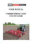
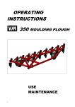
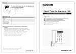
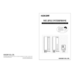
Operating Intsructions Tassu 420 Operating Instructions Espotel Tassu 420 - Control Automation System for Seeding Drill Espotel Oy Kappelitie 6, FI-02200 Espoo FINLAND Version: 1.5 Muutos pvm. 02.07.08 Hyv.-- 1 (16) Operating Intsructions Tassu 420 Version history Version 0.1 0.2 1.0 1.1 1.2 1.3 Date 28.11.05 27.12.05 28.12.05 04.01.06 11.01.06 23.10.06 Made by HM HM HM HM HM RR 1.4 1.5 20.11.06 22.02.08 JJS MaKo Espotel Oy Kappelitie 6, FI-02200 Espoo FINLAND Changes First version Chapters 1.4 and 1.5 added Corrections after inspection realized, 1st approved version Images added, chapters 3.5 and 3.6 specified Alarm messages updated in chapter 3.5 Added to Fig. 6 in chapter 3.6 the description of operation of the backspace key for the seeding furrow counter added to the programme version 1.04. Addition on page 10, Addition on page 12 text in Fig. 6 Added; description of operation of the driveline markers Version: 1.5 Muutos pvm. 02.07.08 Hyv. -- 2 (16) Operating Intsructions Tassu 420 3 (16) Contents Version history 1. 1.1. 1.2. 1.3. 1.4. 1.5. 2 COMMISSIONING, MAINTENANCE AND STORAGE ........................ 4 Parts of Control Automation System............................................................... 4 Characteristics of Control Automation System ..................................... 5 Installation of Control Automation System ........................................... 6 Maintenance of Control Automation System ........................................ 6 Storing the Control Automation Syste m .............................................. 7 2. USER INTERFACE .............................................................................. 7 3. 3.1. 3.2. 3.3. 3.4. 3.5. 3.6. STANDARD EQUIPMENT ................................................................... 7 Selecting the seeding plot .................................................................... 7 Seeding reports .................................................................................... 8 Area meter ........................................................................................... 8 Using the working hour counter............................................................ 9 Rotation guards for shafts .................................................................... 9 Spraying-track function ........................................................................ 12 4. 4.1. 4.2. 4.3. 4.4. 4.4.1. 4.4.2. ADDITIONAL AND OPTIONAL EQUIPMENT...................................... 14 Electric remote control of fertilizer feeding ........................................... 14 Electric control of hydraulic blocks ....................................................... 14 Level guards for the hoppers ............................................................... 14 Operation of the driveline marker ......................................................... 14 Manual ................................................................................................. 15 Automatic ............................................................................................. 15 Espotel Oy Kappelitie 6, FI-02200 Espoo FINLAND Version: 1.5 Muutos pvm. 02.07.08 Hyv. -- Operating Intsructions Tassu 420 1. COMMISSIONING, MAINTENANCE AND STORAGE 1.1. Parts of Control Automation System A B C D E 4 (16) Tassu 420 control unit I/O device CAN bus cable Power supply cable Wire harness for tractor A B D C E Fig. 1: The parts for the Control Automation System (the control unit A in the picture lacks a control facility for the driveline marker) Espotel Oy Kappelitie 6, FI-02200 Espoo FINLAND Version: 1.5 Muutos pvm. 02.07.08 Hyv. -- Operating Intsructions Tassu 420 5 (16) Fig. 2: This is a newer Tassu equipped with the driveline marker facility. 1.2. Characteristics of Control Automation System Operating voltage: Operating temperature: Mechanical structure: Official regulations: Fuse current rating: Fuse type: 8 – 32 VDC (Rated 12/24 V) -20 … +50 ºC IP54 Control automation system meets the requirements according to EMC Directive 89/336/EEC 30 Amp Littelfuse MIDI® 0498030 or equivalent 30 Espotel Oy Kappelitie 6, FI-02200 Espoo FINLAND Version: 1.5 Muutos pvm. 02.07.08 Hyv. -- Operating Intsructions Tassu 420 6 (16) Fig. 3: Fuse, wire harness for tractor 1.3. Installation of Control Automation System The I/O device complete with sensors and cables ís ready-installed in the seeding drill at the Vieskan Metalli factory and does not require any further adjustment by the user. A wire harness for tractor use comes with the appliance and needs to be permanently installed in your tractor The 2-pole flat connector in the wire harness also needs to be permanently installed, for example, in the mudguard, while the other ends of the cable need to be connected directly to the battery poles The fuse box must be attached to the tractor so that the battery lead is not subjected to stretching or squeezing. The fuse in the wire harness must not be removed or replaced by a bigger one. Make sure of the correct polarity while connecting the wire harness: connect the yellow lead to the minus-pole of the battery and the red one to the plus-pole. The length of the wire harness is 6 metres. Attach any extra length to the tractor chassis so that it is not subjected to mechanical strain. Install the control unit in the tractor cabin. A fixture of steel is delivered with the unit. While selecting the installation position, ensure that the CAN bus cable, coming from the control unit, is not subjected to any stretching squeezing. The installation must never jeopardize traffic safety. 1.4. Maintenance of Control Automation System The Control Automation System does not need any specific maintenance (such as, for example, changing of batteries). Espotel Oy Kappelitie 6, FI-02200 Espoo FINLAND Version: 1.5 Muutos pvm. 02.07.08 Hyv. -- Operating Intsructions Tassu 420 7 (16) The Control Automation System does not include any parts that the user can replace or repair. Do not undo the attachment screws of the boxes. In the event of any malfunctions or matters related to the warranty, please contact Vieskan Metalli. The warranty does not cover devices that have been repaired or modified. Use compressed air to remove dust from the 2-pole flat connector in the tractor’s wire harness or the power supply cable of the seeding drill. The control unit MUST NEVER BE WASHED USING A HIGH-PRESSURE WASHER NOR SUBMERGED IN WATER. Use a dry or moist cloth to clean it. As necessary, apply mild soap solution. Do not use industrial solvents. The IO device in the seeding drill MUST NOT BE WASHED USING A HIGHPRESSURE WASHER. Use compressed air to remove dust from the top of the IO-device box 1.5. Storing the Control Automation Syste m Keep the Control Automation System in dry indoor storage when it is not in use. Put a dust cap on the 2-pole flat connector in the tractor’s wire harness when it is not in use. When storing, position the power supply cable and the CAN bus cable of the seeding drill so that neither rain nor melting water have direct access to the connectors’ contact pins. Do not remove the IO-device with sensors from the drill, when putting it into storage for winter 2. USER INTERFACE All the control unit’s menus are illustrated blown up on the last page of these instructions The illustration may also be used as a quick reference. 3. STANDARD EQUIPMENT As standard, the appliance is equipped with instruments for monitoring and controlling the basic functions of the seeding drill Operation of the additional equipment is described in chapters 3.1 - 3.6. The standard equipment comprises: Area meter Operating hour counter Rotation guards Spraying-track automation 3.1. Selecting the seeding plot The area and working hour information for twenty-four different plots may be saved in the memory of the Control automation system . In addition, data about the total area and total time are saved in the memory. Espotel Oy Kappelitie 6, FI-02200 Espoo FINLAND Version: 1.5 Muutos pvm. 02.07.08 Hyv. -- Operating Intsructions Tassu 420 8 (16) To select the plot for seeding, proceed as follows: a) With the Control Automation System in Start mode, select the menu by clicking the MENU button. b) SELECT AREA is shown on the display - press the OK button. c) Select the desired plot (1-24) using the arrow keys and accept the selection by pressing OK. d) Using the arrow keys, select ACTIVATE and press OK. You can reset the data for any of the 24 individual areas - i.e. the area and time by selecting the ERASE operation instead of activation. The Control Automation System requests confirmation before erasing the data, accept this by pressing OK. Note! The data for total area and time for all 24 plots may be reset in one go under the SEEDING REPORT menu (see chapter 3.2 in the operating instructions). 3.2. Seeding reports The area and time data for the plots are shown under the SEEDING REPORT menu. To select this menu, proceed as follows: a) With the Control Automation System in Start mode, select the menu by clicking the MENU button. b) Scroll through the menu using the arrow keys until the message SHOW SEEDING REPORTS shows on the display. Continue by pressing OK. c) Now you can scroll through the seeding reports for individual plots (1-24) using the arrow keys. d) The “Summary of all plots” report is shown at the end, after plot 24. The total area and time information for all 24 plots may be reset in one go by pressing OK. The Control Automation System requests confirmation before erasing the data, accept this by pressing OK. 3.3. Area meter During seeding, the area for each plot is calculated individually. Simultaneously also the total area reading in the counter grows. The area of the selected plot in hectares is shown in the upper right corner of the START menu. To reset the area counter, first select the desired plot in the SELECT AREA menu and then select “Erase”. (as instructed in chapter 3.1 of these operating instructions). This also resets the time elapsed for seeding the plot. The total area data is reset under the SHOW SEEDING REPORT menu (chapter 3.2). Espotel Oy Kappelitie 6, FI-02200 Espoo FINLAND Version: 1.5 Muutos pvm. 02.07.08 Hyv. -- Operating Intsructions Tassu 420 3.4. 9 (16) Using the working hour counter The working hour counter calculates the time used for seeding the plot. Simultaneously also the total time reading in the counter grows. The working hour counter is switched on and off by pressing the OK button while in the START menu. The message “Timer” and the reading for the working hour counter in hours and minutes show up on the display. The working hour counter stops automatically for a moment when moving to other menus using the MENU button. To reset the working hour counter, first select the desired plot in the SELECT AREA menu and then select “Erase”. (as instructed in chapter 3.1 of these operating instructions). This also resets the time elapsed for seeding the plot. The total time data is reset under the SHOW SEEDING REPORT menu (chapter 3.2). 3.5. Rotation guards for shafts The rotation guards for shafts are actuators with a built-in rotation guard and a lock-up spool for the feeding groove. Fig. 4: Lock-up spool and rotation guard The seeding drill is equipped with four separate actuators located on the fertilizer and grain shafts by the wheel tracks of the tractor. The lock-up spools are numbered as follows: Spools 1 and 2 are on the fertilizer shaft. Spool 1 is located close to the drive mechanism for the drill, on the left-hand side with respect to the driving direction. Spools 3 and 4 are on the grain shaft. Spool 3 is located close to the drive mechanism for the drill, on the left-hand side with respect to the driving direction. Espotel Oy Kappelitie 6, FI-02200 Espoo FINLAND Version: 1.5 Muutos pvm. 02.07.08 Hyv. -- Operating Intsructions Tassu 420 1 2 3 4 10 (16) Fig. 5: Numbering of the lock-up spools The Control Automation System monitors rotation of the fertilizer and grain feeding shafts. If either of the shafts stops rotating during seeding because of a malfunction, the control unit issues an alarm. Alarm! Rotation guard 1 2 Reset [OK] The alarm message above indicates that the fertilizer shaft is not rotating. Alarm! Rotation guard 3 4 Reset [OK] The alarm message above indicates that the grain shaft is not rotating. Espotel Oy Kappelitie 6, FI-02200 Espoo FINLAND Version: 1.5 Muutos pvm. 02.07.08 Hyv. -- Operating Intsructions Tassu 420 11 (16) Alarm! Rotation guard 1 2 3 4 Reset [OK] The alarm message above indicates that neither of the feeder shafts is rotating. In addition, the rotation guards supervise the operation of the lock-up spools (see chapter 3.6) while the spraying-track function is switched on. During making of spraying-tracks, the automation system observes the skidding of the lock-up spool. If skidding occurs, the control unit issues an alarm: LOCK-UP SPOOL OUT OF ORDER 1 Reset [OK] The figure in the alarm message refers to the ordinal of the defect lock-up spool (see Fig. 5) Press the OK button to reset the alarms. The sound alarms are switched on and off under the CHANGE SETTINGS menu. The rotation guard may be switched off under the same menu. The rotation guard can also be set to monitor exclusively either the lock-up spools 1&2 or 3&4. Espotel Oy Kappelitie 6, FI-02200 Espoo FINLAND Version: 1.5 Muutos pvm. 02.07.08 Hyv. -- Operating Intsructions Tassu 420 3.6. 12 (16) Spraying-track function Applying the spraying-track function leaves unsown tracks on the field. Spraying-tracks corresponding to the width of the tractor tread are created by means of lock-up spools on the fertilizer and grain shafts which stop the rifle feeder. The Control Automation System monitors the lifting and lowering of the drill between the work and transport positions and, based on this so-called work position pulse, calculates the correct moment to switch the spools on and off for making the spraying-tracks. Spray-tracks: 2/4 Spray-tracks: 1/4 Spray-tractks YES Spray-tracks: 3/4 Spray-tracks: 1/4 Fig. 6: Functional principle of the spraying-track function Under the CHANGE SETTINGS menu, set the spraying-track data, i.e. how many pulses the work position sensor must submit before the spraying-tracks are set to be created (number 4 in the illustration). To achieve this, proceed as follows: a) With the Control Automation System in Start mode, select the menu by clicking the MENU button. b) Scroll through the menu using the arrow keys until the message CHANGE SETTINGS shows on the display. Continue by pressing OK. Espotel Oy Kappelitie 6, FI-02200 Espoo FINLAND Version: 1.5 Muutos pvm. 02.07.08 Hyv. -- Operating Intsructions Tassu 420 13 (16) c) Using the arrow keys, select ”Spraying-track data”. d) Now you can change the set value for the spraying-track counter between 1-8 by pressing OK. e) Return to the START menu by pressing the MENU button. While the spraying-track function is switched on, the spraying-track data and the number of pulses submitted by the work position counter show on the display (for example, 1/4 - i.e. one pulse has been received so far and the spraying-tracks are set to be created after every 4th pulse). As the number of pulses in accordance with the preset spraying-track data are received, the lock-up spools will be switched on and the message YES shows on the display. As the sprayingtrack function is switched off, the message NO shows on the display and the drill may be lifted and lowered without affecting the reading of the work position counter. Alue: 01 0,00 ha Ruisku-urat: 1/4 Ajastin: 0:01 Hydraulilohko: 0 3 Alue: 01 0,00 ha Ruisku-urat: EI Ajastin: 0:01 Hydraulilohko: 0 While the message ”Spraying-tracks” is shown on the display: 1/4 stands for the present value of the work position pulse, in this case 1. As the drill is lifted to the transport position and, after that, returned to the work position, the value will change to 2, etc. Number 4 stands for the integer used for counting the sprayingtracks. So, the reading 4/4 indicates that the spraying-tracks will be done. This means that the message “Spraying-tracks YES” is shown on the display and the lock-up spools are switched on.. The Pause feature of the spraying-track function may be activated by pressing the TASSU button while in Start mode. Thus the drill may be lifted and lowered between the work position and the transport position without disturbing the spraying-track calculation. The message NO on the display means that the spraying-track function is switched off. If the TASSU button is pressed a second time, the operation may be continued normally from the previous location. If you keep the TASSU button depressed for more than 3 second, the spraying-truck counter will step backward. You can use this option, for example, when you must lift the machine in the transport position in the middle of the field. Fig. 7: Setting the spraying-track function to PAUSE mode Espotel Oy Kappelitie 6, FI-02200 Espoo FINLAND Version: 1.5 Muutos pvm. 02.07.08 Hyv. -- Operating Intsructions Tassu 420 4. 14 (16) ADDITIONAL AND OPTIONAL EQUIPMENT The additional and optional equipment presented in this chapter must be ordered from the Vieskan Metalli factory. The equipment is also available for retro-fitting. Items of additional equipment are: Electric remote control of fertilizer feeding Electric control of hydraulic blocks Level guards for the hoppers 4.1. Electric remote control of fertilizer feeding The motor for electric remote control of fertilizer feeding may be controlled using the arrow keys under the START menu. During setting, one of the following messages shows on the display: Fertilizer rate increases Fertilizer rate decreases Please refer to the table affixed to the drill for feeding rate setting for fertilizer. 4.2. Electric control of hydraulic blocks While in the START menu, the desired hydraulic block (2 pcs.) may be activated using the FUNC button. The hydraulic blocks are not active, while “hydraulic block 0” is selected. 4.3. Level guards for the hoppers The level guards for the hoppers issue an alarm at the lower limit. Then the control unit issues an alarm: ALARM! Grain hopper empty ALARM! Fertilizer hopper empty Press the OK button to reset the alarms. The sound alarms may be switched on and off under the CHANGE SETTINGS menu. 4.4. Operation of the driveline marker Espotel Oy Kappelitie 6, FI-02200 Espoo FINLAND Version: 1.5 Muutos pvm. 02.07.08 Hyv. -- Operating Intsructions Tassu 420 15 (16) The driveline marker is used for marking on the field surface the centre-line for the next pass. This prevents adjacent drivelines from overlapping or diverging leaving an empty space between the passes. The marker can either be operated manually – the left-hand, the right-hand or both markers being in the lowest position - or in automatic mode where operation of the driveline marker is automatically switched from one side to the other every time the machine is lifted at the end of the field. The operation is controlled using a turn switch with the following positions in clockwise order; OFF, LEFT, AUTOMATIC, RIGHT and BOTH. In addition to this, Tassu has two signal lights for indication of the markers’ state. For safety reasons, the operation of the driveline markers shall be switched off for the start of Tassu; as required, Tassu provides a reminder to do so. Set the driveline marker switch to the locked position 4.4.1. Manual In manual mode, the operator can select the lowering of either the left-hand, the right-hand or both markers. The signal light always indicates the selected mode. Using only the turn switch is not enough to make the driveline markers turn; in addition to this the seeding drill must also be either lifted or lowered. Lifting the seeding drill always lifts all the driveline markers to their upper position irrespective of the position of the turn switch and lowering makes all the desired driveline markers lower to their lowest position. 4.4.2. Automatic In automatic mode, only one of the markers is in its lower position. The marker operation is switched automatically to the opposite side as the drill is lifted all the way up. When the drill is in its upper position, the signal light indicates which of the markers will lower next. The first marker to operate can be selected using the turn switch, by turning it to the “manual” position either on the right-hand or on the left-hand side and after that, returning the switch to the “automatic” position. Espotel Oy Kappelitie 6, FI-02200 Espoo FINLAND Version: 1.5 Muutos pvm. 02.07.08 Hyv. -- Operating Intsructions Tassu 420 16 (16) 1 Area: 01 0,00 ha Spraying tracks: 1/4 Timer: NO YES Valve block: 0 Area: 01 0,00 ha Spraying tracks: NO Timer: 0:01 Valve block: 0 2 OK MENU OK SELECT AREA SELECT AREA >Area: 01 0.00 ha Area: 02 0.00 ha Area: 03 0.00 ha Area: 01 0,00 ha Spraying tracks:1/4 Timer: 0:01 Valve block: 0 SHOW SEEDING REPORTS ACTIVATE >RESET OK SEEDING REPORT Area: 1 Area: 0.00 ha Time: 0 h 00 min RESETTING DATA Do you want to reset? AREA 1 Accept [OK] 24 x Fertilizer rate decreases OK Area: 01 0,00 ha Spraying tracks:1/4 Timer: 0:01 Valve block: 1 CHANGE SETTINGS CHANGE SETTINGS >Spraying track data 4 Sound alarm YES Rotation guard YES 1. Start Menu SELECT LANGUAGE OK Use ARROW buttons for controlling the adjustment motor for feeding rate of fertilizer (option) OK MENU Use OK button for accepting and changing the value or setting Use MENU button to return to step back and to return directly to start menu Use HYDR button to select the hydraulic valve block (option) Use MENU button to select the menu with rest of the operations Version: 1.5 Muutos pvm. 02.07.08 Hyv. -- RESETTING DATA Reset all data? Accept [OK] OK Use ARROW button for moving up and down in the menus Use OK button for stopping and starting the counter Espotel Oy Kappelitie 6, FI-02200 Espoo FINLAND Areas, total 0.00 ha 0 h 00 min Reset [OK] 2. How to move in menus Use Spaying-track button to interrupt the spraying-track function (to interrupt counting of work position pulses) MENU SELECT OPERATION OK Fertilizer rate increases OK OK >English Estonian German Finnish