1
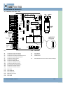
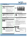
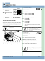
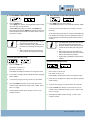
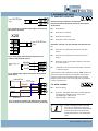
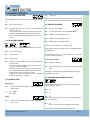
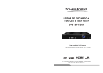
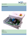
Control Unit DGC 1 Operating instructions OVITOR OY SIENITIE 24 FIN‐00760 HELSINKI FINLAND Tel. +358 (0) 207 106 600 Fax. +358 (0) 207 106 601 ENG 3. GENERAL SAFETY INSTRUCTIONS 1. CONTENTS 1. 2. 3. 4. 5. 6. 7. 8. 9. 10. 11. 12. 13. 14. 15. Contents ............................................................................................2 Key to symbols...................................................................................2 General safety instructions ...............................................................2 Overview of products ........................................................................3 4.1. Control unit DGC 1 PCB...............................................................4 Installation .........................................................................................5 5.1. General information ...................................................................5 5.2. Mains connection .......................................................................5 5.3. Programming the device ............................................................5 5.4. Reset to factory settings.............................................................6 5.5. Operation mode..........................................................................6 5.6. Limit type ....................................................................................6 5.7. Electronic open limit adjustment................................................7 5.8. Electronic close limit adjustment................................................7 5.9. 1/2 open feature.........................................................................8 Safety edge ........................................................................................8 6.1 After run.......................................................................................8 6.2 Extra safety edge .........................................................................8 6.3 Wire tighten.................................................................................8 Advanced settings .............................................................................9 7.1. Photocell functions .....................................................................9 7.2. Auto closing ................................................................................9 7.3. Car wash function .....................................................................10 7.4. Run time control .......................................................................10 7.5. Reverse time .............................................................................10 7.6. Service counter .........................................................................10 7.7. Encoder positioning failure.......................................................10 Force control....................................................................................11 8.1. Force control .............................................................................11 8.2. Manual force control, open ......................................................11 8.3. Manual force control, close ......................................................11 8.4. Force control adaptive settings ................................................11 Inverter ............................................................................................12 LED error codes (D15)......................................................................13 Display in ”RUN” mode....................................................................14 Display status (in ”RUN” mode) ......................................................16 Functions of the lamp PCB ..............................................................17 Technical data..................................................................................18 Declaration of incorporation of partly completed machinery........19 2. KEY TO SYMBOLS Danger of personal injury! The safety instructions must be observed! Warning! Danger to property The safety instructions must be observed! Product liability The function and safety of the equipment is only guaranteed if the warning and safety instructions included in these op‐
erating instructions are adhered to. Ovitor Oy is not liable for any personal injury or damage to property that occurs as a result of the warning and safety instructions being disregarded. Using the equipment for its intended purpose The DGC 1 controls are designed only for controlling gates and doors. Target group Only qualified and trained electricians may connect, pro‐
gramme and service the controls. Qualified and skilled elec‐
tricians must: • Have knowledge of the general and specific and accident prevention regulations. • Have knowledge of the relevant electrical regulations. • Be trained in the use and care of appropriate safety equipment and clothing. • Be capable of recognising the dangers associated with electricity. Instructions for installation and connection • Before commencing electrical works, the system must be disconnected from the electricity supply. Measures must be taken that the electricity supply remains discon‐
nected for the duration of the works. • Local safety regulations must be observed. • Mains cables must be laid separately from control ca‐
bles. Information • Special information • Reference to other sources of 2 ‐ Control Unit DGC 1 / Rev. 1.0 11/10
Regulations and bases for testing For connecting, programming and servicing, the following regulations must be observed (the list is not exhaustive). Construction product standards • EN 13241‐1 (Products without fire resistance or smoke control characteristics) • EN 12445 (Safety in use of power operated doors ‐Test methods) • EN 12453 (Safety in use of power operated doors ‐
Requirements) • EN 12978 (Safety devices for power operated doors and gates ‐ Requirements and test methods) Electromagnetic compatibility • EN 55014‐1 (Radio disturbance, household appliances) • EN 61000‐3‐2 (Disturbances in supply systems ‐harmonic currents) • EN 61000‐3‐3 (Disturbances in supply systems ‐voltage fluctuations) • EN 61000‐6‐2 (Electromagnetic compatibility (EMC) ‐Part 6‐2: Generic standards ‐ Immunity for industrial environ‐
ments) • EN 61000‐6‐3 (Electromagnetic compatibility (EMC) ‐Part 6‐3: Generic standards ‐ Emission standard for residen‐
tial, commercial and light‐industrial environments) Machinery guidelines • EN 60204‐1 (Safety of machinery, electrical equipment of machines, part 1: general requirements) • EN 12100‐1 (Safety of machinery. Basic concepts, gen‐
eral principles for design. Basic terminology, methodol‐
ogy) Low voltage • EN 60335‐1 (Household and similar electrical appliances ‐Safety) • EN 60335‐2‐103 (Particular requirements for drives for gates, doors and windows) Control Unit DGC 1 / Rev. 1.0 ‐ 3 4. OVERVIEW OF PRODUCTS N
E
E
R
G
D
E
R
L
N
O
I
D
A
R
1
1
2
X
1
R
T
6
0
1
8
X
789
. D
L
E E
Y R
+ Y2
TO
ET
FO
AH
SP
8 9 7
2 2 2
D D D
R
EN
O
TI
RS
ER
VE
NV
I
2
K
E
T
I
H
W
4321
NN
WE
OE
RR
BG
1
K
.E
RU
OE
G
2 D
kN
8PE
E
GL
DA
EC
I
YT
TP
EO
F
A
S
2
2
X
.
C
EP
PO
T
SS
/
O
MR
RO
EO
HD
T
123 4
1234
3
2
X
2
X
4
3
2
1
5
4
3
2
1
1
X
W
V
U
E
P
E
P
N
3
L
2
L
1
L
V
+ -Y I
N
2 D
AT
1 N A T
E
EN S
+ G T A
FE L
A
D D AP U
SO P
E
TR
UE
LD
OO5E
8P
SC4
BNs
Y
AEr
T
Terminals for mains connection Terminals for motor connection Terminals for command and safety devices Terminal for push buttons in the lid Terminal for radio receiver Terminal for lamp PCB Terminal for Safety photo 1 Terminal for absolute encoder Terminal for LED pad in the lid Extra terminals for safety device Terminals for inverter version Terminals for inverter version B
MB
AC
LP
4
S
123 4
WWW W
SSS S
0
1
X
7
X
5
E
U
L
B
0
1987654321
234
0
2
X 4321
R
O
S
S
E
C
O
R
P
1
4
1
D
213
SSS
1
P
9
X
6
X
32
54
E
S
O
L
C
W
S
T
I
M
I
L
N
E
P
O
V
4
2
+
2
O
T
O
H
P
R
DO
ES
EN
PE
SS
Key: X1 X2 X3 X5 X7 X8 X12 X13 X14 X20 X22 X23 D10 D12 D14 D15 D27 D28 00:00
5
1
D
N
E
P
O
N
O
I
T
C
N
U
F
O
G
2
1
D
Y
A
L
P
S
I
D
P
O
T
S
1234512345
P
O
T
S
.
R
E
M
E
2 P.
1
9
1 OT
1
5 4
8
1
X
X
OE
12
X 1
X
3
X
X
LD
1
X
0 1234567890123456789 123456
3 1234567891 1111111112222222222
X
4.1. CONTROL UNIT DGC 1 PCB D29 S1 S2 S3 P1 LED: CLOSE STOP‐button OPEN‐button CLOSE‐button Potentiometer for Force controls manual settings LED: STOP LED: OPEN limit LED: CLOSE limit LED: Error indication LED: Creep LED: OPEN 4 ‐ Control Unit DGC 1 / Rev. 1.0 11/10
5. INSTALLATION 1
X
E
P
N
3
L
2
L
1
L
Warning! To guarantee that the equipment func‐
tions properly, the following points must be ensured: • The gate or door is installed and op‐
erational. • The MFZOvitor drive motor is installed and ready for operation. • The command and safety devices are installed and ready for operation. • The control unit DGC 1 is installed Connect mains to terminal X1 5
4
3
2
1
5.1. GENERAL INFORMATION Fig. 1. Terminals for mains connection 5.3. PROGRAMMING THE DEVICE Information For the installation of the gate/door, the MFZ drive motor and the command and safety devices, the relevant manu‐
facturer’s instructions are to be ad‐
hered . 5.2. MAINS CONNECTION Danger! To guarantee that the controls function properly, the following points must be en‐
sured: • The mains voltage must correspond to the voltage stated on the type plate. • The mains voltage must be the same as the voltage of the drive. • For a three‐phase current, a clockwise rotating field is required. • For a permanent connection, an all‐pole main switch must be used. • For a three‐phase connection, only 3‐
way automatic circuit breakers (10A) may be used. Warning! Before switching on the controls for the first time, a check must be carried out after completing the wiring to ensure that all the motor connections at the motor and at the controls are securely fixed. All control voltage inputs are galvanically isolated from the supply. • The door will always run in a deadman mode when programming • Make sure that no emergency stop or other stop is activated before entering programming mode Program the control by open enclosure. (Without lid) Find OPEN ‐ CLOSE ‐ STOP push‐buttons and a 4 pole DIP switch on the PCB. 1. To select programming mode, change (S4) DIP switch no. 1 to ON position. 2. Navigation in programming mode is done by STOP pushbutton (S1). STOP pushbutton is used to toggle be‐
tween parameter number and parameter value. 3. OPEN (S2) and CLOSE (S3) push‐buttons are used to se‐
lect parameter number or change the parameter value. If display shows RUN these buttons run the door up and down in a deadman mode. 4. Parameter explanation: 01:01
Parameter value. Values shown in this manual are fac‐
tory settings. Parameter number Control Unit DGC 1 / Rev. 1.0 ‐ 5 4
S
123 4
WWW W
SSS S
5. INSTALLATION DIP switches (S4): SW1 Programming mode (chapter 5.3.) SW2 Display status (Chapter 13) SW3 SW4 Reset to factory settings Fig. 2. DIP switches S4 (chapter 5.4.) 5.4. RESET TO FACTORY SETTINGS Reset to factory settings by changing S4 DIP switch SW4 to ON position and activate STOP and OPEN push‐buttons for 2 s. The display will flash with ”FAC” and program version number will be shown. • Remember to change DIP switch back to OFF position 2 1 Fig. 2. Opening rotation direction, when door operator mounted as shown in the picture. 5.5. OPERATION MODE Parameter number 01 Parameter value: 01: Hold‐to‐run (deadman) OPEN Hold‐to‐run (deadman) CLOSE 02: Impulse OPEN Hold‐to‐run (deadman) CLOSE 03: Impulse OPEN Impulse CLOSE 04: Impulse OPEN * Impulse CLOSE *0,5 s reverse by stop on force control in opening direction • The door will always run in a deadman mode in programming mode • Value shown after heading is the fac‐
tory setting 5.6. LIMIT TYPE Parameter number: 11 Parameter value: 00: Mechanical limits (micro switches) 01‐04: Not in use with Ovitors control units 05: Electronic limits ‐ rotation direction 1 (check fig. 2) 06: Electronic limits ‐ rotation direction 2 • After changing to electronic limits, a new power up is needed to start com‐
munication. 6 ‐ Control Unit DGC 1 / Rev. 1.0 11/10
5.7. ELECTRONIC OPEN LIMIT ADJUSTMENT 5.8. ELECTRONIC CLOSE LIMIT ADJUSTMENT + • Learning OPEN limit ‐ Press STOP push‐button until the display flashes ”RUN” ‐ Run the door to open position. ‐Press STOP push‐button to confirm new OPEN limit. (The display will indicate OPEN limit symbol for about 2 s and the display will automatic ally switch back to active parameter number) + • Learn CLOSE limit (electronic limits) ‐ Press STOP push button until the display flashes “RUN” ‐ Run the door to closed position (normally 5 cm from the floor) ‐Press the STOP push‐button to confirm new CLOSE limit. (The display will indicate close limit symbol for about 2 s and the display will automatically switch back to active number.) • 1/2 OPEN limit cannot be active during programming (parameter 16). • Photo in the door frame (parameter 31) cannot be active during learning of lim‐
its. • When relearning limits, parameter 41 and 51 will be reset to factory settings. Electronic open limit fine tuning + • Fine tune OPEN limit: more open → values 6‐9 less open → values 1‐4 Press OPEN or CLOSE push‐button to change the value. • If the value is changed: Press STOP push‐button (Display shows ”RUN”) • Try the fine tuning by running the door up and down. • Press the STOP push‐button to save and return to pa‐
rameter value. (adjustment range is max. ± 0,8 % of the door run range) • Pressing STOP without value change → return to pa‐
rameter number. • 1/2 OPEN limit cannot be active during programming limits (parameter 16) • Photo in the door frame (parameter 31) cannot be active during learning of lim‐
its • When relearning limits parameter 41 (force control) and 51 (run time control) will be reset to factory settings • Safety edge is disabled in programming mode!! Electronic close limit fine tuning + • Fine tune CLOSE limit: more closed → values 6‐9 less closed → values 1‐4 Press OPEN or CLOSE push‐button to change the value. • If the value is changed: Press STOP push‐button (Display shows ”RUN”) • Try the fine tuning by running the door up and down. • Press the STOP push‐button to save and return to pa‐
rameter value. (adjustment range is max. ± 0,8 % of the door run range) • Pressing STOP without value change → return to pa‐
rameter number. Control Unit DGC 1 / Rev. 1.0 ‐ 7 5. INSTALLATION 5.9. 1/2 OPEN FEATURE Parameter number 16 Parameter values: 00: 1/2 OPEN limit not in use 01: Mechanical limit switches (value 00 in parameter 11) 1/2 OPEN limit switch connected to X3 terminals 15 and 16. Short circuit terminals 15 and 16, if not in use. Electronic limits (parameter 11 values 5 and 6) OPEN commands to 1/2 OPEN position, if X3 terminals 15 and 16 connected (ON/OFF) selector switch is ON: 02: 1/2 OPEN position = 4/8 open 03: 1/2 OPEN position = 5/8 open 04: 1/2 OPEN position = 6/8 open 05: 1/2 OPEN position = 7/8 open 1/2 OPEN command by a push‐button connected in X3 ter‐
minals 15 and 16. 06: 1/2 OPEN position = 4/8 open 07: 1/2 OPEN position = 5/8 open 08: 1/2 OPEN position = 6/8 open 09: 1/2 OPEN position = 7/8 open 1/2 open auto close 00 = No auto close from 1/2 open position 01 = Auto close from 1/2 open position (Auto close must be activated in parameter 32)
8 ‐ Control Unit DGC 1 / Rev. 1.0 6. SAFETY EDGE • Safety edge must be connected but not activated before this setup • If the controller has observed a wrong type of edge select, the display will show “ERR” 01 = PNE edge 02 = 8k2 electrical edge 03 = Optical edge 04 = Not in use with Ovitor’s control units 6.1. AFTER RUN 00 = No after run >00 = After run active ‐ after run time 0,01 ‐ 0,3 s Safety edge monitoring will bypass the CLOSE limit and wait for a test impulse from the safety edge. If the impulse is not received within time selected with parameter 22 , door will be stopped and the control notifies a safety edge failure. 6.2. EXTRA SAFETY EDGE 00 = No extra safety edge 01 = Extra safety edge parallel to the primary safety edge 02 = Extra safety edge ‐ STOP in the opening direction NOTE! Extra safety edge has to be PNE or 8k2 Ω and the same type as primary safety edge. 6.3. WIRE TIGHTEN Wire tighten parameter set the time that door will reverse after safety edge hits the floor. 00 = No wire tighten function 01 = Wire tighten 5 ms 02 = Wire tighten 10 ms 03 = Wire tighten 20 ms 04 = Wire tighten 30 ms 11/10
34
22
7. ADVANCED SETTINGS A
N
U
I.E
A
U
TE
R
2 O
kNT
8PN
U
T
7.1. PHOTOCELL FUNCTIONS PNE or 8k2 Ω safety edge A
N
I.U
A
E
TUR
2EO
kNT
8PN
U
T
43
0
2
X
Fig 3. Pneumatic or electrical safety edge is connected to X3 terminals 23 and 24 21
PNE or 8k2 Ω safety edge NN
WE
OE
RR
BG
NA
EN
NU
IE
T
R
PO
OT
N
U
T
E
T
I
H
W
Safety edge, op‐
tical 567
222
Fig. 4. Safety edge chosen with parameter 23 is con‐
nected to X20 terminals 3 and 4 Fig. 5. Optical safety edge is connected to X3 terminals 25,26 and 27 N
I
T
E
H
Ä
L
A
E
K
S
U
R
BROWN A
T
S
U
M
BROWN BLUE BLUE 9012
1222
A
E
K
S
U
R
A
T
S
U
M
BLACK NN
EE
NN
I
I
NN
II
S
S
TRANSMITTER BLACK N
I
T
O
N
A
A
T
S
A
V
RECEIVER Fig. 6. Transmitter‐receiver‐type photocell is connected to X3 terminals 19, 20, 21 and 22. Parameter 31 value 02. Photocell 1: Plug in module to terminal X12 Photocell 2: External photocell, connect to X3 terminals 20,21 and 22. 00 = No photocell 01 = Photocell 1 connected 02 = Photocell 2 connected 03 = Photocells 1 and 2 connected Parameter value 04—07: Only possible with electronic lim‐
its. 04 = Photocell 1 connected and mounted in the door frame.* 05 = Photocell 2 connected and mounted in the door frame.* 06 = Photocells 1 and 2 connected and photo 1 mounted in the door frame.* 07 = Photocells 1 and 2 connected and photo 2 mounted in the door frame.* *”RUN” mode is now available by pressing STOP. Location of photo will now be learned by running from close to open position. The door will stop when the photo is no longer blocked and the control unit will change back to parameter number automatically. 7.2. AUTO CLOSING 00 = No auto closing xx = seconds 1 ‐ 990 (after 99 the value is flashing quickly indicating x10 multiplier for auto close time ‐ e.g 18 (flashing) = 180 seconds 18 (no flashing) = 18 seconds) • If stop or emergency stop is activated more than 5 s with door in open posi‐
tion, the auto close will be interlocked to prevent closing. Reset of interlock by CLOSE push‐button or ”GO FUNCTION” close. Control Unit DGC 1 / Rev. 1.0 ‐ 9 7. ADVANCED SETTINGS 7.3. CAR WASH FUNCTION NOTE! Available when auto closing is selected by parameter 32. 00 = No car wash function xx = Photo active time in 0,1 s (e.g. 15 = 1,5 s) adjustable 1‐
30 units = 0,1 ‐ 3 s Count down of auto closing time starts only if photo has been activated more than “photo active time”. Door shall be complete closed before start of a new cycle. 7.4. RUN TIME CONTROL Both limits must be set before selecting adaptive run time! 00 = No run time control 01 = Run time 20 s 02 = Run time 40 s 03 = Adaptive run time. ”RUN” position is now available by pressing STOP. Run the door from closed to open position without any stop. (keep press OPEN) When run time is learned (by open limit) the “RUN” will stop flashing and the display will automatically switch back to active parameter number. Adaptive run time is learned time + 12,5 %. Below 10 s learned time, fixed 1 s is added. + 7.5. REVERSE TIME Safety edge xx = Reverse time of safety edge in 1/100 s, adjustable 0,004 ‐ 0,99 s. E.g. 00 = 0,004 s 05 = 0,05 s Photo xx = Reverse time of safety edge in 1/100 s, adjustable 0,05 ‐ 0,99 s. 10 ‐ Control Unit DGC 1 / Rev. 1.0 E.g. 30 = 0,3 s NOTE! This reverse time is also used as speed reversing time and reverse by OPEN push‐button, when the door is closing. 7.6. SERVICE COUNTER 00 = No service countdown 01 = 15 open cycles before service (for test only) 02 = 5000 open cycles before service 03 = 10000 open cycles before service 04 = 20000 open cycles before service Reset for new countdown or selecting value: Press STOP to select parameter value. Press OPEN or CLOSE to select value. Press STOP again min. 2 s. ”CLR” is shown for 2 s in display to confirm new countdown. Service count reaction 00 = Display shows E:04 01 = Switch to hold‐to‐run (a deadman) control and display E:04 If LED pad is mounted: Service LED will light when service countdown reach to 0. 7.7. ENCODER POSITIONING FAILURE Only available with electronic limits. The reaction time for missing positions (E:09) 00 = 1 s 01 = 2 s 02 = 4 s (failure reset by hold‐to‐run operation to find both limits or limit learning again) 03 = 4 s (failure is shown shortly, resetting automatically) NOTE! No limit monitoring by selecting value 03! 11/10
8. FORCE CONTROL 8.1. FORCE CONTROL + • All mechanical spring adjustments and door limits must be adjusted before selecting force control. 00 = No force control 01 = Force control manual adjustment (1300 ‐ 1750 rpm) 02 = Force control manual adjustment (2600 ‐ 3500 rpm) Force control adaptive learning 03 = Force control by adaptive learning (Ovitor PNP‐
encoder, connected to speed input X3 terminal 17) 04 = Force control by adaptive learning (singleturn en‐
coder) • ”RUN” mode is now available by pressing STOP . • Run the door 2 complete door cycles from closed posi‐
tion without any stop. (keep pressing OPEN or CLOSE). • When learning is finished the ”RUN” will stop flashing in 2 s and the display will automatically switch back to ac‐
tive parameter number • If new adaptive learning is wanted, press stop 2 times until “RUN” is flashing again. 8.2. MANUAL FORCE CONTROL, OPEN Parameter 41 values 01 or 02. 1. Press STOP push‐button until the parameter value is active (flashing). 2. If this is the first adjustment, turn potentiometer P1 clock‐wise to max position. 3. Press CLOSE to reset for new value and run the door to closed position. 4. Press OPEN continuously and turn slowly P1 until the door is stopped. Turn a little back. The display shows approximately P1 percent value . 5. Check that the door can complete full OPEN cycle with‐
out stops. 6. By pressing STOP the value is saved and display switch to parameter number. The value must be saved before switching away from programming mode. NOTE! If no OPEN or CLOSE has been pressed, no new value is changed 8.3. MANUAL FORCE CONTROL, CLOSE Parameter 41 values 01 or 02. 1. Press STOP push‐button until the parameter value is ac‐
tive (flashing). 2. If this is the first adjustment, turn potentiometer P1 clock‐wise to max position. 3. Press OPEN to reset for new value and run the door to open position. 4. Press CLOSE continuously and turn slowly P1 until the door is stopped. Turn a little back. The display shows ap‐
proximately P1 percent value. 5. Check that the door can complete full CLOSE cycle with‐
out stops. 6. By pressing STOP the value is saved and display switch to parameter number. The value must be saved before switching away from programming mode. 8.4. FORCE CONTROL ADAPTIVE SETTINGS Parameter 41 = 3 00 = Force control delay 0,8 s Stopped by low speed ‐0,5 % Wear limit (from initial values) ‐5 % 01 = Force control delay 0,8 s Stopped by low speed ‐1,0 % Wear limit (from initial values) ‐5 % 02 = Force control delay 0,8 s Stopped by low speed ‐1,5 % Wear limit (from initial values) ‐5 % 03 = Force control delay 0,8 s Stopped by low speed ‐2,0 % Wear limit (from initial values) ‐5 % 04 = Force control delay 0,8 s Stopped by low speed ‐2,5 % Wear limit (from initial values) ‐6 % 05 = Force control delay 0,8 s Stopped by low speed ‐3,0 % Wear limit (from initial values) ‐7 % Update of set point 0,3 % / 10 door cycles Control Unit DGC 1 / Rev. 1.0 ‐ 11 9. INVERTER Single turn force control Parameter 41 = 4 02 = Force control delay 0,4 s Stopped by low speed ‐3,5 % Wear limit (from initial values) ‐7 % 01 = Force control delay 0,4 s Stopped by low speed ‐7,0 % Wear limit (from initial values) ‐14 % Update of set point 0,9 % / 10 door cycles Reaction time for low speed observing about 2,4 s • The motive force needed to move the door may increase over time due to wear and tear, changes in balanc‐
ing and similar reasons • Once the force needed to move the door has increased to an extent that the motor revolving speed has changed as much as determined by the value “wear limit”, the control notifies with an error code E:08 12 ‐ Control Unit DGC 1 / Rev. 1.0 NOTE! This function is only for special variant of DGC 1 con‐
nected with extern inverter and with electronic limits! Opening low speed set point 00 = 10 % before open limit 01 = 20 % before open limit 02 = 30 % before open limit 03 = 40 % before open limit Closing low speed set point 00 = 10 % before close limit 01 = 20 % before close limit 02 = 30 % before close limit 03 = 40 % before close limit 11/10
10. LED ERROR CODES (D15) Used when electronic limits are selected Flashes on error LED Error explanation 1 No answer from encoder 2 Limits not learned 3 Not in use Solving error • Check connections • RS 485 A and B may have interchanged • Learn limits • Check that parameter 11 value is correctly selected. (Rotation direction 1&2) • Possible user error . Both limits are the same • Encoder error 4 Calculation error 5 Not in use 6 Not in use 7 Mechanical failure 8 Change the encoder Encoder ‐ Failure operating volt‐ • Check connection and supply voltage age • Change the encoder Control Unit DGC 1 / Rev. 1.0 ‐ 13 11. DISPLAY IN ”RUN” MODE The display will show the status of limits, some inputs and error codes in ”RUN” mode. During power up, the software version is showed shortly Parameter Description • Nothing active (4 chairs symbol) • Door is stopped between limits and no errors are found • Open limit active • Normal symbol to help adjustment and fault finding • Close limit active • Normal symbol to help adjustment and fault finding • 1/2 OPEN limit active • Normal symbol to help adjustment and fault finding • STOP active • Normal symbol to help adjustment and fault finding • OPEN push‐button active • Normal symbol to help adjustment and fault finding • CLOSE push‐button active • Normal symbol to help adjustment and fault finding • GO FUNCTION active • Normal symbol to help adjustment and fault finding • Photocell 1 active • Normal symbol to help adjustment and fault finding • Photocell 2 active • Normal symbol to help adjustment and fault finding • Safety edge active • Normal symbol to help adjustment and fault finding • Normal symbol indicating door running up • Normal symbol indicating door running down • Not in use • Error code • Monitoring failure of safety edge if this function is activated • Error code • Door is stopped by force control when this function is active. • Symbol is also shown if the adaptive force control is not learned, when returning to run mode 14 ‐ Control Unit DGC 1 / Rev. 1.0 11/10
Parameter Description • Error code • Door is stopped by run time control • Service counter decremented to 0 • Service the door and reset for new countdown. See parameter 58. • Error in the safety edge circuit • Test cycle before close fails • Tacho failure when force control is active • Speed wear failure • Motive force needed to move the door has increased over the wear limit. • Check the mechanical condition and balancing of the door. Relearn force control. • Encoder failure. Door started, but the position is not changing. • Door is stopped after raction time (parameter 81) and error E:09 is displayed • Limits must be relearned. • EEPROM counter failure or position failure • The door cannot be closed after error on photo or safety edge • By a special code the door can close one time in hold‐to‐run mode. Press and hold STOP while press‐
ing 22111 (2=CLOSE push‐button; 1=OPEN push‐button) Control Unit DGC 1 / Rev. 1.0 ‐ 15 12. DISPLAY STATUS (IN ”RUN” MODE) • To select DISPLAY STATUS → close the door and switch S4 DIP SW 2 to ON position • The door cannot be moved when display status is active Parameter and 16 ‐ Control Unit DGC 1 / Rev. 1.0 Description •
•
•
•
Electronic counter status The display is flashing between least significant digits and the most significant digits E.g.(362 and 086) = 362*1000 + 086 = 362086 door openings Press STOP to select next status available •
•
•
•
Last 10 errors Press OPEN to select newer error Press CLOSE to select older error If there are no errors the display will show: • By the end of the 10 registered errors the display will show: Upper end Lower end • Switch S4 DIP SW2 to OFF position to exit the DISPLAY STATUS 11/10
13. FUNCTIONS OF THE LAMP PCB The function of red/green traffic light can be chosen according to the following table. 0 = OFF 1 = ON Name SW1 SW2 SW3 SW4 Functional description L1 0 0 0 0 • Red light when door is not open • Green light when door is open L1G 1 0 0 0 • Red light when door is not open • Green light is blinking when door is open L1R 0 1 0 0 • Red light is blinking when door is not open • Green light when door is open L1RG 1 1 0 0 • Red light is blinking when door is not open • Green light is blinking when door is open L2 0 0 1 0 • Red light when the door is opening or closing • Green light when the door is open • No light when the door is closed L2G 1 0 1 0 • Red light when the door is opening or closing • Green light is blinking when the door is open • No light when the door is closed L2R 0 1 1 0 • Red light is blinking when the door is opening or closing • Green light when the door is open • No light when the door is closed L2RG 1 1 1 0 • Red light is blinking when the door is opening or closing • Green light is blinking when the door is open • No light when the door is closed L3 0 0 0 1 • Red light when the door is not open or closed • Green light when the door is open • Warning when closing from open limit switches. Red light ap‐
pears before closing. L3G 1 0 0 1 • Red light when the door is not open or closed • Green light is blinking when the door is open • Warning when closing from open limit switches. Red light ap‐
pears before closing. L3R 0 1 0 1 • Red light is blinking when the door is not open or closed • Green light when the door is open • Warning when closing from open limit switches. Red light starts blinking before closing. L3RG 1 1 0 1 • Red light is blinking when the door is not open or closed • Green light is blinking when the door is open • Warning when closing from open limit switches. Red light starts blinking before closing. Control Unit DGC 1 / Rev. 1.0 ‐ 17 14. TECHNICAL DATA Dimensions: Assembling height: Power supply via L1, L2, L3, PE: Protections: Consumptions Of the control: Control voltage: Control inputs: Control outputs: RS 485 A and B: Safety chain: Input safety edge: Relays output: Operation temp: Storage temp: Air humidity: Vibrations: Type of protection: Weight: 190 x 300 x 110 vertically at the wall, min. at a height of 100 mm. 400V, 50/60Hz, power inp. max 5,5kW 8 A; duty cycle 60% for a max running time of 120 s. 10A K –characteristic max. 250 mA 24 VDC, max. 250 mA, protected by self‐
resetting safety for external sensors Disposal Waste electrical products and batteries should not be disposed of with household waste! Disposal should be carried out according to DI‐
RECTIVE 2002/96/EC OF THE EUROPEAN PAR‐
LIAMENT AND OF THE COUNCIL of 27 January 2003 on waste electrical and electronic equip‐
ment and DIRECTIVE 2006/66/EC OF THE EUROPEAN PARLIAMENT AND OF THE COUNCIL of 6 Sep‐
tember 2006 on batteries and accumulators. 24 VDC, all inputs are to be connected free of potential, min. signal time for incoming control command > 100 ms 24 VDC, max. 250 mA Only for electronic final switch RS 485 level All input connections must be potential‐
free; if safety circuit is interrupted, no further electrically powered movement of the drive is possible For electrical safety edge 8,2 kΩ , pneu‐
matic safety edge tai optical safety edge If inductive loads are switched to (e.g. relays or breaks), they must be equipped with corresponding interference measures (recovery diode, varistores, RC modules). Operating contact free of potential, min. 10 mA; max 230 VAC / 4A Contacts used once for power switch are not able to switch mini power anymore ‐10 oC … +45 oC ‐25 oC … +70 oC to 80 % non condensing Assembling works with less vibration, e.g. at a masonry wall IP 65 solid installation about 1.8 kg 18 ‐ Control Unit DGC 1 / Rev. 1.0 11/10
15. DECLARATION OF INCORPORATION OF PARTLY COMPLETED MACHINERY Ovitor Oy Sienitie 24 00760 Helsinki Finland Description and identification of the partly completed machinery: Control unit DGC 1 The essential requirements of EC Machinery Directive 2006/42/EC have been applied and fulfilled for the above mentioned machinery to be used with industrial doors, gates and barriers. The relevant technical documentation has been compiled in accordance with Annex VII, Part B of EC Machinery Directive 2006/42/EC. In addition the partly completed machinery is in conformity with the EC 2006/95/EC Low Voltage Directive LVD, 2004/108/EC Electromagnetic Compatibility EMC and 2002/95/EC the Restriction of the use of certain Hazardous Substances in Electrical and Electronic Equipment RoHS. The above listed products are delivered according to the following standards to the extent to which they may be applicable: EN ISO 12100‐1, EN ISO 12100‐2, EN 60204‐1+A1, EN 60335‐1, EN‐55014‐1, EN 61000‐3‐2, EN 61000‐3‐
3, EN61000‐6‐2, EN61000‐6‐3, EN 60439‐1+A1, EN 60439‐3+A1+A2, EN 60529, EN 13241‐1, EN 60355‐
1, EN 60335‐2‐103, EN 13241, EN 12453, EN 12445, EN 12978 SFS‐Inspecta Sertifiointi OY has issued a certificate ascertaining that the manufacturer's quality system meets the require‐
ments of standard SFS‐EN ISO 9001:2008 and the general guidelines ABC 200, certificate 1229‐04. We undertake, in response to a reasoned request, to supply it in electronic form to the market surveillance authorities within a reasonable period. The party authorized to compile the technical documentation is: Ovitor Oy / Engineering Manager Sienitie 24 00760 Helsinki Finland The devices are not intended to function independently but as part of an electrically operated machine. As regards the installation, settings and servicing of the of the machinery, the instructions issued by us for the type of instal‐
lation in question must be observed. The partly completed machinery must not be put into service until the final machinery into which it is to be incorporated has been declared in conformity with the provisions of the Machinery Directive. Helsinki, 16th of June 2010 _______________ Hannu Pyrhönen Managing Director Ovitor Oy Control Unit DGC 1 / Rev. 1.0 ‐ 19