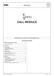
1
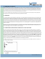
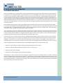
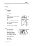
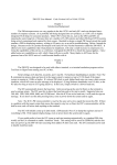
CONTROL UNIT E6LDC
FOR FIRE DOORS WITH ONE DRIVE UNIT
USERS MANUAL
OVITOR OY
SIENITIE 24
FIN-00760 HELSINKI
FINLAND
Tel. +358-207 106 600
Fax. +358-207 106 601
1. CONTENTS
1. Contents..................................................................................................................................2
2. Overview of product................................................................................................................3
2.1 Operation......................................................................................................................3
2.2 Alarm from a door closing automatically at fire shut speed...........................................3
2.3 Principle of operation ....................................................................................................4
2.4 Control and alarm of the charge level of batteries.........................................................4
2.5 Double-quittance button of the fire alarm .....................................................................4
2.6 Charging system and batteries ......................................................................................4
3. Installation and operation .......................................................................................................5
3.1 Installation of the control and the drive unit.................................................................5
3.2 Main switch of the unit.................................................................................................5
3.3 Limit switches and adjustment of door stopping locations............................................5
3.4 Adjustment of door movement speed...........................................................................5
3.5 Running time limiter.....................................................................................................6
4. Monitoring unit SAVU2............................................................................................................7
5. Service and troubleshooting ....................................................................................................8
5.1 Troubleshooting of monitoring unit SAVU2...................................................................8
5.2 Checking the operation of fire door system ..................................................................8
5.3 Troubleshooting instructions/Service............................................................................9
6. Technical Data .......................................................................................................................10
7. Declaration of incorporation of partly completed machinery ................................................11
8. DC Drive ................................................................................................................................12
9. Releasing the drive unit for service........................................................................................13
2 - Control Unit E6LDC / Rev 1.3
2. OVERVIEW OF PRODUCT
E6LDC is battery-driven control unit of OVITOR OY for fire doors. Control unit E6LDC is intended for doors operating in continuous use, in which opening and closing occurs automatically or on impulse, the door being equipped with safety devices.
This manual does not describe the detailed functioning, the adjustments or the settings of an E6L-based unit; this information is available in the user’s manual of the E6L control unit. In fire door drives, the running time limit differs from the standard functioning of the E6L unit and is described separately in this manual.
The control unit E6LDC may not be used direct as a part of a fire alarm system for the real property, but the property fire
alarm system can control the fire door function with a potential-free contact.
2.1 OPERATION
In a normal situation, the door operates on hand hold or in accordance with the automatism ordered. In a fire situation, the
controller requires a potential-free signal from the alarm system, a detector, etc. In this case, the controller closes the door
from all positions at slow fire shut speed after the set time. When pressing the safety open button in a press key or the like,
the door opens at normal speed to the width of the required passageway and closes automatically at slow fire shut speed. If
the door is opened manually, the controller closes it automatically at slow fire shut speed. In controllers containing automatism, other opening and safety devices, excluding stop buttons, are normally skipped. In individual cases, safety devices can
be left in operation.
Stop buttons must be anti-locking. Open buttons are skipped in a fire situation, because they have a closing contact, and in a
fire the control cables may first melt together. The safety open button has been implemented with an opening contact, so
that a cable melting in a short circuit does not cause an opening.
2.2 ALARM FROM A DOOR CLOSING AUTOMATICALLY AT FIRE SHUT SPEED
A fire door closing by itself, without safety device control, in a fire situation may cause a danger situation. It is possible to
receive a separate alarm from direct current controller DC1 of control unit E6LDC that warns, when the door closes in a fire
alarm. It is also possible to change the alarm to warn always, when the door moves. The change is made with jumper S1 on
the board of direct current controller DC1. In position P (factory setting), the alarm is given only in a fire shut situation, and in
position N the alarm is given whenever the door moves. The position means the short-circuiting of the middle and the letterside pin of the pin terminal with a short circuit plug; cf. the attached figure no. 1. The alarm voltage 24VDC is conducted from
the battery to terminal 1 of the controller, and the alarm information is obtained from terminals 2 and 3. The voltage is connected to zero from terminal 3, so both poles of the alarm device have a voltage of 24VDC, when it is out of operation. The
maximum permitted load is 200mADC. If the alarm device is more powerful than required by the maximum permitted load
current, a relay must be used as an aid. The board has a zero diode pre-connected.
In addition, separate alarms on the movements of the door are available for control unit E6LDC; cf. E6L user’s manual, section ‘TRAFFIC LIGHT CONTROL’.
Fig. 1.
Control Unit E6LDC / Rev 1.3 - 3
2. OVERVIEW OF PRODUCT
2.3 OPERATING PRINCIPLE
The closing of a fire door equipped with door automatism must be secured by designing the operation of the door to be such
that the door closes in the event of a power failure, or by using a power source independent of mains current. Control unit
E6LDC operate on batteries continuously charged with mains voltage. After the mains voltage has been cut off, the charge of
the batteries lasts for at least ten openings and closings.
2.4 CONTROL AND ALARM OF THE CHARGE LEVEL OF BATTERIES
If the voltage of the batteries falls below the set value, the red warning light in the cover of the unit flashes. It is also possible
to receive voltage information 24VDC or potential-free contact information (extra relaying) on an alarm. The functioning of
the lamp in the cover of the unit is checked by switching the main switch of the unit to the zero position and after this back
to the I position: if the lamp is intact, it flashes. Normally, the alarm starts flashing, when the charge state of the batteries has
fallen and the door is operated on power drive.
If the control unit must be set in another place than in a visible place in the direct vicinity of the fire
door, it has to be sure that the warning light ‘REDUCED BATTERY VOLTAGE’ is seen in time.
2.5 DOUBLE-QUITTANCE BUTTON OF THE FIRE ALARM
In the control unit lid is an yellow light button with a text ‘FIRE ALARM – DOUBLE-QUITTANCE’. The light goes on when a fire
alarm coming or if the supply coming from batteries will be cut, e.g. by turning the main switch to 0-position and back. If the
main switch has been turned from 0-position back to the I-position the alarm light goes on and it will be reset by pressing
the quittance button for long enough. If a fire detector has given an alarm, the detector will not be self-reset very fast even
the reason for the alarm has gone away, e.g. the burnt charge from a truck. In such a cases the alarm will be reset by switching the detectors off. The alarm from detectors must reset depending of the type of detector with one or more long enough
quittance button presses after what the alarm leaves off the control unit and detectors alike. If a detector is detecting and
the reason for the alarm is not gone away, the alarm will be renewed when releasing the button.
2.6 CHARGING SYSTEM AND BATTERIES
The batteries of the control unit are charged from the mains voltage with a transformer and regulator DC2. The regulator
sets the correct charging current of the batteries, ensures that the batteries are not charged to an excessive voltage and
controls the charge state of the batteries. The control of the charging current and voltage lengthens the service life of the
batteries. The frequency of use and environmental conditions greatly affect the service life of the batteries. In normal use,
the expected service life of the batteries is four to five years.
In the normal application, the batteries used are two pieces of series-connected 12V, 7Ah batteries. The batteries are structurally completely closed, so there is no danger of leaks, and their installation position is free. The batteries need not be serviced, but they must be replaced at least every five years. The batteries must be replaced simultaneously with the identical,
symmetrically full-charged, rechargeable batteries. The replacement is allowed to do only by a person familiarized with the
job and when changing the control unit main switch must be in 0-position. The right polarity of the batteries’ connection
must be checked when changing. Leaking batteries must be immediately replaced.
Before breaking up the control unit must the batteries be removed. The removed batteries must be carried out to a suitable
disposal point.
4 - Control Unit E6LDC / Rev 1.3
3. INSTALLATION AND OPERATION
3.1 INSTALLATION OF THE CONTROL AND THE DRIVE UNIT
The control unit must be installed at least 530 mm wide from the door opening. The door operator must be installed at the
extreme end of the slide track from the door opening.
3.2 MAIN SWITCH OF THE UNIT
The unit is always constructed in a metal case. In order to avoid accidental switching off of the charging of the batteries, the
main switch of the unit is generally installed within the unit. The main switch of the unit cuts off the mains voltage feed of
the charger from the controller and the current feed of the batteries to the unit. DO NOT LEAVE THE MAIN SWITCH IN THE 0
POSITION.
3.3 LIMIT SWITCHES AND ADJUSTMENT OF DOOR STOPPING LOCATIONS
In normal use, four limit switches are required in the drive unit of the door: open limit, closed limit, deceleration limit and
fire alarm opening limit. The contacts of the open and the closed limit open, when the door reaches its extreme position.
The contacts of the deceleration limit close a little before the closed position of the door, with the motor regulator smoothly
slowing down and dropping the speed to zero. The door stops without jerks. The limit must be adjusted so that the slowing
down of the speed is smooth from full speed to zero. If the door drifts the end of its path, the closing of the limit must be adjusted to a little later. Normally, the deceleration limit is not used in folding fire doors, because the door mechanics cause a
natural deceleration to the movement of the door.
In E6LDC drives, the contacts of the fire alarm limit CLOSE, when the door is driven in the fire alarm state with the fire alarm
open button and the door has opened sufficiently for passage through the doorway. If a safety edge is used in control unit
E6LDC, a safety edge limit is also required in the drive mechanism. The contacts of the safety edge limit close 5...50mm before the closed position of the door. The safety edge limit removes from the drive the opening function of the safety edge,
and instead stops the door at an impulse from the safety edge. This function prevents the door from opening again, when
the safety edge hits the floor or a frame. Check, when necessary, the functioning of the safety edge in the E6L user’s manual,
section ‘LIMIT SWITCHES AND ADJUSTMENT OF DOOR STOPPING LOCATIONS’.
3.4 ADJUSTMENT OF DOOR MOVEMENT SPEED
The movement speeds of the door are adjusted with trimmers RT2 and RT3,
located in the front panel of direct current controller DC1. With the maximum
speed adjustment trimmer RT3, you can set the door speed in a normal drive
situation to 70...100%. Set the closing speed of a fire alarm situation with the
fire shut speed adjustment trimmer RT2. The adjustment range is 30...70% of
the full speed of normal operation; cf. the attached figure no. 2. The fire shut
speed ought to be set relatively slow, as the door closes automatically without safety device control. The test run must be carried out with care, making
sure that the door closes completely also at fire shut speed. The complete
closing of the door may, at the final stage of closing, require relatively great
force of the drive mechanism, and at a slow speed the torque of the motor
may be too small. In such a case, the fire shut speed must be increased. This
situation is typical in folding fire doors, for instance.
Fig. 2.
Control Unit E6LDC / Rev 1.3 - 5
3. INSTALLATION AND OPERATION
3.5 RUNNING TIME LIMITER
Control unit E6LDC have, as a safety device, a running time limiter which stops the motor after the expiry of the permitted
running time. The running time limiter is located in direct current controller DC1. In a fire alarm, the running time limiter of
the direct current controller is skipped. E6LDC-control has an own running time limiter. It will be adjusted according to the
control unit E6LDC manual. After the running time limiter has operated in the closed direction, the door is opened for 2 seconds and the door re-closes after the automatic closing time is passed, no separate quittance is needed. If the running time
limiter has stopped the door in the open direction, automatic closing occurs. In fire door use during an alarm, the door may
not remain in any open position. In fire door use during an alarm, programmatically in E6LC control the door doesn’t remain
in any open position.
The permitted running time is set with trimmer RT1, located in the front panel of direct current controller DC1 (see figure
no. 2, section ‘ADJUSTMENT OF DOOR MOVEMENT SPEEDS’), at 2...10s longer than the running time required for the normal
travel of the door. The normal time range is linear 3...30s. The time can be increased by a change made in the board of DC1.
Turning the trimmer clockwise increases the permitted running time.
The running time can be set, for example, as follows. Drive the door from the closed limit to the open limit and measure the
travel time required by the door. Drive the door closed. Disconnect the cable of the motor, press the open button and measure the time that passes till LED L1, ‘running time exceeded’, lights in the front panel of DC1. The time should be longer by
the above-mentioned amount than the measured real running time of the door.
If the set continuous running time of the motor is exceeded, red LED L1 lights in the front panel of direct current controller
DC1, and the door stops. This can happen, for example, if the door cannot make its normal movement. The fault indication
disappears, and the LED turns off, when either of the directional contactors releases. This happens in drive directions on
hand hold, when the control button is released, and in drive directions moving at impulse, when the stop button is pressed.
If the running time limiter has stopped the door, check BEFORE driving the door in either direction that:
• the door can move freely in its guide tracks from one extreme position to the other;
• there are no foreign objects between the hinges, sections, etc. of the door;
• the door has not frozen immobile;
• nothing else is preventing the normal movement of the door.
If everything is in order, drive the door in the opening or closing direction from one extreme position to the other, observing
the door throughout the travel. If the fault indication is repeated, the resistance against movement of the door has for some
reason increased, and/or the voltage of the battery has fallen, reducing the revolution speed of the motor and slowing down
the movement of the door. The time can be set longer, but it is also important to find out the reason why the travel time set
at the introduction of the door has increased.
6 - Control Unit E6LDC / Rev 1.3
4. MONITORING UNIT SAVU2
Control unit E6LDC can be equipped with a double-channel monitoring unit SAVU2 for detecting the condition of the function of fire doors smoke detectors and their circuit in detector sockets, where are no separate relay output to control the
logic of fire door in alarm situations. When the smoke detector installed in the socket gives an alarm or in case of cable failure, breaks the circuit controlled by the monitoring unit and the door control system operates according to the chosen
mode.
SAVU2 is installed in the separate base SEMS, installed with the Din-rail, in accordance with fig. 3.
Note the polarity
If the other channel is not in use, 12 kΩ
resistor must be connected
To the next detector
Socket DB701 for smoke detector, max 4 pcs/channel
DIN-rail
12 kΩ 1/ terminator to last terminals
Control Voltage
Relay
Fig. 3. Monitoring unit SAVU2
Since SAVU2 has two channels, it can be used for the indication of one or more detectors’ alarm, or cable malfunction. To
both channels may be connected 4 detectors maximum. The detector line connected to SAVU2 must have a 12kW 1% terminal resistor in the last detector socket. With the help of the idle current that runs through the terminal resistor, the SAVU2
can indicate a possible sensor circuit disconnection or malfunction. Always make sure that the terminal resistor is installed
on the final detector socket, if there are more than one detectors connected in parallel, see fig. 3. When connecting sockets,
please note that the circuit resistance of the used cables must be no more than 100kW.
SAVU2 has two separate, identical supervising circuits for monitoring detector sockets’ and their cables’ status. Both circuits
monitor both channels. If one supervising circuit breaks one or more components, the other circuit can indicate the alarm
and malfunction.
SAVU2 will be connected according to the case-specific wiring diagram. When connecting it must be noted that the control
voltage which should switch off is connected to the terminal 46 and it leaves terminal 47. The zero potential of the electronics is to the terminal 54. When the SAVU2 monitoring unit is used for only one channel, to the terminals of the other channel
must be connected a 12kW 1% resistor. In normal deliveries the resistors are pre-connected to the terminals of both channels. If there is only one channel, SAVU2 monitors detectors using both supervising circuits.
The monitoring unit SAVU2 is intended to use for controlling fire doors only with control unit E6LDC. The monitoring unit SAVU2 like the fire door control units may not be used for example as a part of a fire alarm system for the real property.
NOTE! If there is a control fuse in the control system which is more than 1A, SAVU2 must be equipped with an own 1A input
fuse.
Control Unit E6LDC / Rev 1.3 - 7
5. SERVICE AND TROUBLESHOOTING
The door and monitoring unit may only be serviced by an authorised service technician.
5.1 TROUBLESHOOTING OF MONITORING UNIT SAVU2
When the amplifier unit is connected to the supply voltage and the detectors don’t alarm and their cabling is undamaged, no
LEDs will be on in the monitoring unit and the circuit of the control system will be unbroken.
When a detector is alarming or the resistance of the detector circuit drops, the yellow LEDs, H1 and H3, will turn on in the
monitoring unit, the control system’s circuit will disconnect and the relay used in control circuit will release.
If the detector circuit disconnects or its resistance increases, the red LEDs H2 and H4 in the monitoring unit, will switch on
and the control system’s circuit will disconnect.
If only one of the LEDs, H1, H2, H3 or H4, is switched on, this means there is a monitoring unit malfunction and the control
system’s circuit is broken. In such a case, the monitoring unit must be replaced.
In a fault situation the door operates alike in a fire alarm situation.
The operation of the detector system and the monitoring unit must be checked regularly, for example whenever the door is
serviced. During the check a false alarm will be given for example with the testing gas of the smoke detector. In that case
must the door control system react according to the chosen mode of operation. When disconnecting the other detector circuit cable or short-circuiting these cables the door control system must also react according to the chosen mode of operation.
5.2 CHECKING THE OPERATION OF FIRE DOOR SYSTEM
The operation of the fire door system must be checked at least twice a year, unless regulations and the door supplier’s instructions require more frequent inspection and service. The service and check-up of the door, the drive mechanism and the
power transmission is carried out in accordance with the device supplier’s instructions.
The inspection of the control system is carried out as follows:
REGULATING DEVICES
1. Check the state, functioning and appropriate markings of the regulating devices required for the normal operation of the
door.
SAFETY DEVICES
2. Check the state, functioning and appropriate markings of the safety devices of the door.
3. Check the state, functioning and appropriate markings of the stop buttons of the door and that stop buttons have not
been replaced with locking push-buttons.
4. Check the state, functioning and appropriate markings of the possible wicket door in the door.
5. Check the state of the battery charge state indicator lamp in the cover of the unit, in accordance with the user’s manual,
section ‘CONTROL AND ALARM OF THE CHARGE STATE OF BATTERIES’.
8 - Control Unit E6LDC / Rev 1.3
OPERATION IN FIRE ALARM WITHOUT MAINS SUPPLY
6. Perform inspection of the fire alarm operation of the unit, with mains supply cut off, in accordance with the user’s manual, section ‘OPERATION’. It is simplest to cut off mains supply by removing the mains supply fuse from the group unit.
Remember that the main switch also cuts off current feed from the batteries to the controller. The fire alarm information
must be given to the unit case-by-case, according to the alarm information used. Check the functioning of the lamp of
the fire alarm clearance button in the cover of unit. The lamp is on, when fire alarm information has been given to the
unit.
7. Check the state of the batteries by carrying out several (more than ten) openings of the door without mains supply. If the
batteries are fully charged in the beginning of testing, the signal light of the battery charge state may not flash, while the
door is being driven. The flashing of the signal light of the charge state may be a sign of the ageing of the batteries and of
the reduction of their charging capacity, in which case the batteries may need to be replaced. In this case, contact the device manufacturer or serviceman in order to have the batteries replaced.
5.3 TROUBLESHOOTING INSTRUCTIONS/SERVICE
Check that the settings described in these instructions and in connection with E6LDC control units in the E6L user’s manual
have been made in accordance with the type and mode of operation of the door in question. Check that auxiliary devices
have been wired in accordance with the drawings, precisely to the terminals reserved for them. The E6L control unit user’s
manual describes in detail the troubleshooting of an E6L-based unit. This manual does not contain a general diagram for fire
door wiring, but precise case-specific drawings are provided for each unit with delivery.
If you cannot make the door function by following the enclosed instructions, it is best to contact the dealer’s service organisation before other measures, such as changing components.
Most malfunctions of electrically operated doors are related to the fixation and connections of peripheral and safety devices. As the fire door control units are equipped with versatile systems indicating the mode of operation, the service can often give more detailed troubleshooting and repairing instructions even by telephone. Before contacting service, find out the
type marking of the control unit, the production number or drawing number on the sticker in the control unit or in the drawing. These help to find the corresponding documents in the archive and to speed up the diagnostics.
When ordering a service man, always indicate precisely:
• the type marking of the control unit, the production number or drawing number on the sticker in the control unit or in
the drawing;
• your name and company etc. and your phone number;
• contact person on the site as well as an accurate street address and the contact person’s phone number;
• invoicing address.
Indicating the order number or mark speeds up the preparation of the work order given to the service man as well as the
servicing.
Control Unit E6LDC / Rev 1.3 - 9
6. TECHNICAL DATA
CONTROL UNIT E6LDC TECHNICAL DATA
Product/structural standard
Operation
Current type
Number of poles
Nominal Voltage Un
Nominal isolation voltage Ui
Control voltage
Nominal current In
Nominal current In
Front fuse (mains feed)
Front fuse of accumulator battery feed
Spare fuse for accumulator battery feed
Transformer overload protection
Resistance against short-circuit ICW
Casing class
Protection from electric shock
Distribution system
EMC operating environment
Dimensions
Weight
EN 60439-1:2005
Collection of Finnish construction regulations E6: Fire doors
AC 50Hz
3
230VAC/24VDC +6%...-10%
400V
24VDC
6A mains voltage side
Driving side according to motor output
Max.10A
20A normal application
20A 1 piece normal application
According to size of transformer
<10kA
IP54 normal application
Protection class I normal application
TN-S normal application
1 and 2
650x400x230 mm, including bush sealing flange in length and signal
lights in cover in height, normal application
26,5 kg normal application
MONITORING UNIT SAVU2 TECHNICAL DATA
Supply voltage
Fuse protecting control system
Reaction time
Transistor output
Un =24 Vdc, min. 16 Vdc, max. 28 Vdc, regulated
max. 1 A
5 ms
2xPNP
NOTE! If there is a control fuse in the control system which is more than 1A, SAVU2 must be equipped with an own 1A input
fuse.
10 - Control Unit E6LDC / Rev 1.3
7. DECLARATION OF INCORPORATION OF PARTLY COMPLETED MACHINERY
Ovitor Oy
Sienitie 24
00760 Helsinki
Finland
Description and identification of the partly completed machinery:
Control unit E6LDC
The essential requirements of EC Machinery Directive 2006/42/EC have been applied and fulfilled for the above mentioned
machinery to be used with industrial doors, gates and barriers.
The relevant technical documentation has been compiled in accordance with Annex VII, Part B of EC Machinery Directive
2006/42/EC.
In addition the partly completed machinery is in conformity with the EC 2006/95/EC
Low Voltage Directive LVD, 2004/108/EC Electromagnetic Compatibility EMC and 2002/95/EC the Restriction of the use of
certain Hazardous Substances in Electrical and Electronic Equipment RoHS.
The above listed products are delivered according to the following standards to the extent to which they may be applicable:
EN ISO 12100-1, EN ISO 12100-2, EN 60204-1+A1, EN 60335-1, EN-55014-1, EN 61000-3-2, EN 61000-33, EN61000-6-2, EN61000-6-3, EN 60439-1+A1, EN 60439-3+A1+A2, EN 60529, EN 13241-1, EN 603551, EN 60335-2-103, EN 13241, EN 12453, EN 12445, EN 12978, EN 50272-2
SFS-Inspecta Sertifiointi OY has issued a certificate ascertaining that the manufacturer's quality system meets the requirements of standard SFS-EN ISO 9001:2008 and the general guidelines ABC 200, certificate 1229-04.
We undertake, in response to a reasoned request, to supply it in electronic form to the market surveillance authorities
within a reasonable period.
The party authorized to compile the technical documentation is:
Ovitor Oy / Engineering Manager
Sienitie 24
00760 Helsinki
Finland
The devices are not intended to function independently but as part of an electrically operated machine.
As regards the installation, settings and servicing of the of the machinery, the instructions issued by us for the type of installation in question must be observed.
The partly completed machinery must not be put into service until the final machinery into which it is to be incorporated
has been declared in conformity with the provisions of the Machinery Directive.
Helsinki, 16th of June 2010
_______________
Hannu Pyrhönen
Managing Director
Ovitor Oy
Control Unit E6LDC / Rev 1.3 - 11
Q1
MAIN
SWITCH
12 - Control Unit E6LDC / Rev 1.3
PÄÄLLE VÄLÄHTÄÄ LAMPPU.
LAMPPUTESTI:
LAMP
TEST: LAMOP FLASHES WHEN
KÄÄNNETTÄESSÄ
PÄÄKYTKIN
MAIN
SWITCH IS TURNED
ON
NOTE!
WHEN
FLASHES,
BATTEHUOM!
KUNLAMP
LAMPPU
VILKKUU,
RY
IS TOO LOW!
ONVOLTAGE
AKUN JÄNNITE
LIIAN MATALA.
DC DRIVE
BATTERY CHARGER
DC2
CONTROL LOGIC
TERMINALS 6 AND 7 +24 VDC
TERMINALS 4 AND 5 0 VDC
AKUN VARAUSTILA
BATTERY
CHARKESKUKSEN
GE STATE
IN
KANNESSA
COVER OF UNIT
HUOM!
NOTE!
SULAKEKOKO
FUSE SIZE ACCORDING TO
MUUNTAJAN
TRANSFORMER CAPACITY
TEHON MUKAAN.
D1=BATTERY VOLTAGE TOO LOW
(LED FLASHES)
D2=CHARGING VOLTAGE IN ORDER
D3=MAINS VOLTAGE IN ORDER
TO ACCUMULATOR
BATTERY
8. DC DRIVE
9. RELEASING THE DRIVE UNIT FOR SERVICE
1. REMOVE THE COVER OF THE LIMIT SWITCH CASING .
2. TAKE THE RELEASING LEVER FROM THE CONTROL UNIT AND PUSH IT TO THE RELEASE SHAFT ACCORDING TO THE PICTURE
3. TURN 90o → DRIVE UNIT IS RELEASED TO MANUAL OPERATION
4. AFTER SERVICE TURN BACK 90o AND MAKE SURE THAT THE MACHINE OPERATION IS ON USE AGAIN. (MOVE DOOR MANUALLY FOR A SHORT DISTANCE)
THE DOOR MUST NOT BE LEFT TO MANUAL OPERATION AFTER SERVICE !!
1.
3.
2.
Control Unit E6LDC / Rev 1.3 - 13