1
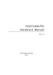
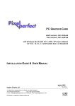
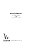
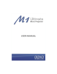
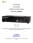
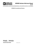
OSSC scanconverter User Manual (fw. 0.26)
1. General info
OSSC is a low-latency video digitizer and scanconverter designed mainly for connecting retro video
game consoles and home computers into modern displays. It converts analog RGB/component video
into digital format, and doubles (or triples) scanlines of a single frame if necessary to generate a valid
mode for digital TVs or monitors. The following list summarizes the current features:
•
detection and digitization of various video modes from 240p to 1080p
• linedouble-support for 240p, 480i, 288p, 576i
• linetriple-support for 240p with 4 different sampling modes
• very low latency (less than 2 input scanlines)
• single-field "deinterlace" for 480i/576i: minimal latency overhead with decent image quality
• quick recover from input video mode change (e.g. 240p<->480i)
• all video processing done in RGB domain - no conversion to YCbCr
• multiple inputs supporting various formats
• RGBS via SCART connector
• RGBHV/RGBS via VGA connector
• YPbPr/RGsB via 3xRCA connector
• full-range 24-bit RGB output through HDMI
• emulated scanlines with configurable strength
• configurable mask for overscan area
• Selectable sampling configuration for 480p input: DTV-480p or VGA 640x480
• Selectable CSC configuration for YPbPr source: Rec. 601 or Rec. 709
2. Board setup and usage
The current prototype board (PCB v1.0) requires the following for operation:
•
A power supply: DC 5V, min. 1A, 2.1mm/5.5mm barrel plug connector (center positive)
•
A remote control using NEC protocol (currently configured only for the bundled remote)
•
A microSD card for firmware upgrade (FAT16 formatted) – <=2GB cards most reliable,
detection of SDHC/SDXC cards may vary
•
A HDMI or DVI display
Except the power switch, the board is operated with a remote control. There is 2 keymaps for the
remote: one for input selection and shortcuts, and one for using the system menu.
The keymaps are illustrated below:
Video mode info
Sys reset
Scanline strength -
Scanlines on/of
Dec./Inc. value
Scanline strength +
Horiz. mask -/+
Next/prev item
Exit Menu
Vert. mask -/+
Enter Menu
Src select:
1 = RGBS (SCART)
2 = RGBHV (VGA) /
RGBS (VGA)
3 = YPbPr (comp.) /
RGsB (comp.)
Figure 1: Main keymap
Figure 2: Menu keymap
After powering on the system, source is selected with keys 1-3. The format of a source (e.g. RGBHV or
RGB on VGA) can be switched by pressing again the respective source key. Shortcut keys are provided
for scanline and mask configuration, which can be also set along with other setting by using system
menu.
There are 4 LEDs on the board indicating the status of the scanconverter, as described below:
•
LED0: Line multiplication active
•
LED1: Remote control activity indicator
•
LED2: System cannot lock properly to input hsync
•
LED3: Variable input line length
LED0
LED1
LED2
LED3
3. System menu options
1. TX mode
Sets the output TX mode
•
HDMI: auxiliary HDMI packets are sent along with video data, such as Infoframes which
indicate color settings (RGB, full-range)
•
DVI: Only video data is sent to the display. Required if target display does not support
HDMI.
2. Scanlines
Controls whether emulated scanlines are drawn on top of the picture
•
Off: No scanlines drawn
•
On: Scanlines drawn on every other (digitize & linedouble modes) or every third (linetriple)
output line
3. Scanline str.
•
12-100%: Strength of the emulated scanlines
4. Horizontal mask
•
0-60 pixels: Controls the size of a mask (black border) generated around the picture in
horizontal direction. Can be used to mask areas which would get hidden in the overscan
region of CRT TVs.
5. Vertical mask
•
0-60 pixels: Controls the size of a mask (black border) generated around the picture in
vertical direction. Can be used to mask areas which would get hidden in the overscan region
of CRT TVs.
6. 480p in sampler
Controls the sampling mode when 525-line progressive signal (“480p”) is detected at input
•
Auto: “VGA 640x480”-mode is selected when the signal comes from RGBHV input. “DTV
480p”-mode is selected with all other inputs
•
DTV 480p: Input is sampled at 858 samples per line, typically associated with 720x480
mode (CEA-861 spec.) used by DTV/DVD equipment and newer game consoles. This
option forces the sampling mode for all inputs, which may be required for optimal image
quality when e.g. Dreamcast with a VGA module is connected to RGBHV input.
•
VGA 640x480: Input is sampled at 800 samples per line, typically associated with 640x480
mode used by PCs. This option forces the sampling mode for all inputs.
7. YPbPr in ColSpa
Controls YPbPr->RGB colorspace conversion coefficients.
•
Rec. 601: Input is assumed to be in Rec. 601 format, which is generally true for SD video
•
Rec. 709: Input is assumed to be in Rec. 709 format, which is generally true for HD video
8. 240p linetriple
Controls whether 240p is linetripled instead of standard linedouble.
•
Off: 240p is linedoubled, resulting to 480p output
•
On: --Experimental-- 240p is linetripled, which results to 720p output. However, the
resulting mode does not have the same parameters (total lines, pixels per line) as the
standard CEA 720p mode, so it is generally accepted only by monitors and not by many
consumer TVs
9. Linetriple mode
Controls the sampling and pixel clock multiplication mode for linetriple
•
Generic 16:9: Uses full horizontal sample rate without pixel multiplication, resulting to
fully utilized 1280x720 output (16:9 aspect).
•
Generic 4:3: Uses 3/4 of full horizontal sample rate without pixel multiplication, resulting
to 960x720 effective area of 1280x720 output (4:3 aspect).
•
320x240 optim.: Uses a sampling rate which matches the DAC rate of 426 dots per line
used by various classic consoles (e.g. PSX, Saturn) in 320x240 mode, resulting to pixelperfect digitization. Output is pixel-multiplied by 3 in horizontal direction, resulting to
960x720 effective area of 1280x720 output.
Note: There is a bug that can sometimes cause picture jittering when this mode is initialized.
A workaround is to toggle “240p linetriple” off and back on until initialization results to
stable output.
•
256x240 optim.: Uses a sampling rate which matches the DAC rate of 341 dots per line
used by various classic consoles (e.g. NES, SNES, MD) in 256x240 mode, resulting to
pixel-perfect digitization. Output is pixel-multiplied by 4 in horizontal direction, resulting to
1024x720 effective area of 1280x720 output.
Note: There is a bug that can sometimes cause picture jittering when this mode is initialized.
A workaround is to toggle “240p linetriple” off and back on until initialization results to
stable output.
10. Firmware update
Firmware can be updated via a microSD-card. Due to an issue in the reference SD device
driver, currently only standard size cards (not SDHC/SDXC) are reliably recognized. The card
must be formatted as FAT16, and the firmware file (ossc.rbf) must be placed on the root folder,
after which firmware can be updated via the instructions on the character LCD.