1
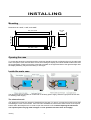
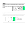
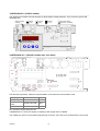
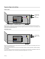
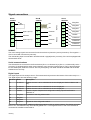
User manual 18.8.2009 Firmware V1.1 2012KCI Weighing display INTRODUCTION 2012KCI is an input card specially designed for Konecranes. It can be placed in any of Nokeval F series large displays, like 1000F4. switch position is changed, the corresponding text is displayed for a while. Each input can be enabled or disabled by a digital input, and the sum of the enabled inputs is displayed. The card provides two 2-8 V analog input channels. The upper end of these can be scaled freely and independently on each channel. Optionally the input card can be companioned with another input card, forming a third analog input. The display unit can be equipped with a serial communications card, providing a RS-232 and a RS-485 port. Nokeval SCL and Modbus RTU protocols are supported. The card allows reading the analog and digital inputs. If configured so, 2012KCI does not update its display at all but allows the display to be controlled over the serial bus. The channels can be tared with a digital input. There is also one digital input that can be used to show "Flt" in the display. A sling select switch position can be indicated with 16 freely programmable display texts. The switch is read via four digital inputs. Whenever the sling The wide power supply range 41...265 VAC will cover most applications, making ordering simpler. Table of contents Introduction......................................................................................................................................................2 Ordering...........................................................................................................................................................3 Installing...........................................................................................................................................................4 Operation.......................................................................................................................................................10 User interface.................................................................................................................................................12 Configuration menu........................................................................................................................................15 SCL protocol..................................................................................................................................................19 Modbus protocol.............................................................................................................................................21 Ascii protocol..................................................................................................................................................23 Calibration menu............................................................................................................................................24 Specifications.................................................................................................................................................25 Quick set-up For a quick set-up, the minimum set of information can be obtained from sections: • Supply voltage and earthing on page 7 • Signal connections on page 8 • Quick configuration menu on page 12 Manufacturer Tel +358 3 3424800 Fax +358 3 3422066 Nokeval Oy Yrittäjäkatu 12 FIN-37100 Nokia Finland Introduction email [email protected] WWW http://www.nokeval.com 2 ORDERING Ordering Example: 1000F4–2012KCI–RS–DI8–48/230VAC Power supply options The order code consists of several parts. The first part describes the large display type, the next parts define the card types (up to three cards), and the last part describes the supply voltage. The large field displays are available with two power supply options: Large display type Nokeval has four cases for large field displays. These are: 575 Five 57 mm digits, plastic enclosure 1000 Three to four 100 mm digits, steel 1100 Five to six 100 mm digits, steel 1800 Three to five 180 mm digits, steel The letter F after the case size tells the type of the internal electronics. Name Voltages -24VDC 24 ±15% VDC or VAC -48/230VAC 41...265 VDC or VAC In some cases the internal electronics unit is not capable of powering the large digits. In this case, there is an auxiliary power supply fitted inside the case. This does not affect the order code. Most common models The number after the letter F defines the number of display digits. 1000F4-2012KCI-RS-DI8-48/230VAC: four 100mm digits, 2 inputs, serial comms, digital inputs, power 48 to 230 VAC. Input card type 1000F4-2012KCI-2012KCI-DI8-48/230VAC: four digits, 3 inputs, digital inputs, power 48 to 230 VAC. These large displays use Nokeval 2000 series input cards. A custom input card 2012KCI has been designed for KCI. (In addition, two older cards 2011KCI and 2211KCI have been used.) Spare parts ordering Other cards Spare input card: 2012KCI-IN 2000-DI8 card provides eight digital inputs. They are used to select input channel to be displayed, to tare the inputs, and to read the sling switch. In the order code, this card is expressed as "-DI8-" only. Spare electronics unit including input card: SP-EL2012KCI-RS-DI8-48/230VAC (or whichever supply and cards) 2000RS is a serial communications card, allowing RS-232 and RS-485 communication with the display unit. In the order code, it is expressed "RS-". Spare ribbon cable from el unit to large digits: SP-CA-EL1000F Spare large digit: SP-100DISP (100 mm digit) If three analog inputs are desired, the display unit can be equipped with two 2012KCI cards. The order code is then 1000F4-2012KCI-2012KCI-DI8230VAC for example. Ordering 3 INSTALLING Mounting Dimensions for 1000F, 1100F, and 1800F: 500, 670 1045 120,130, 210 188,250, 375 147, 210, 330 455, 625, 1025 482, 650, 1030 Opening the case To access the electrical connections and the small user interface used for configuring the unit, the steel case has to be opened. First unscrew all the screws surrounding the display, then lift off the black steel frame and the red plexiglass. Finally unscrew the screw that is located on the right hand side of the rightmost digit. Now the display assembly may be turned away on its hinges. Inside the main case The left picture shows the parts in models with no auxiliary power supply, while the right picture shows with an auxiliary power supply. The electronics unit The electronics unit may be opened or detached from the case. To open it, unscrew the four M3 screws that are holding the cover on its corners. If the unit has to be detached, unscrew the other screws on its top and bottom sides. Normally there is no need to open the electronics unit. Caution! Opening the electronics unit exposes parts carrying lethal voltages on units powered with more than 24 V supply! Installing 4 Jumpers All the jumpers are factory set to serve most of the installation situations and normally need no attention. 2012KCI The input card 2012KCI jumpers are factory set. However their correct position is shown in the picture: FltSw J6 POL J2 J5 In2 Gnd In1 +24V 2000-DI8 The digital input card 2000-DI8 does not have any jumpers. 2000-RS The serial communications card 2000-RS has jumpers for RS-485 bus termination and fail-safing. The factory default is no termination, no fail-safe, which is usable in most situations. Only if the RS-485 bus is longer than 50 m, the termination should be engaged. 2000-RS J3 D1+ D0Common TxD Common RxD Installing 5 No term, no failsafe. Middle of the bus devices. Term, no failsafe. Last device on the bus. Term and FS. Last device on the bus, if there is no other fail-safes. 1000FBAS24 V1.0 (24VDC models) The electronics unit base card has jumpers for large display voltage selection. They are factory set but still illustrated here. Display voltage selection Num58 (8.7V) Num100 (9.5V) Num180 (11.7V) Aux power supply: jumpers do not matter Always closed Close with Num180 * 1000FBAS230 V1.1 (48/230V models after June 2009) J1 J8 J5 J10 J2 K2 K1 POL ISP The DIP switch positions, read from top downwards. K2.2 means the second switch of K2. Display type 575F (8.5V) 1000F, 1100F (9.5V) 1800F (12V) K1 ON-ON-ON-OFF K2.2 OFF ON-OFF-OFF-ON OFF OFF-ON-ON-ON ON K2.3 and K2.4 should always be ON. 1000FBAS230 V1.1 does not require an auxiliary power supply even at 1800F6. The middle pins of the microcontroller programming connector ”ISP” have to be shorted with a 2mm jumper. Installing 6 Supply voltage and earthing 24VDC model Main case Earthing 9 8 Electronics unit 7 Pow er Power supply 24 VDC or 48 VAC. Any polarity. Slot C 0.0 Slot B Slot A Ribbon cable to the digits Small display + buttons Tw o cable glands Bring the supply voltage to the connector indicated in the picture. It is recommended to earth the enclosure using the M4 screw provided for additional protection against disturbances. A pre-fuse is not necessary, but if one is used, it should be at least 2 AT. 48/230VAC model Main case Earthing Electronics unit N L Pow er Power supply 48, 115, or 230 VAC Slot C 0.0 Slot B Slot A Bring the Live and Neutral wires to the electronics unit as in picture. A pre-fuse is not necessary, but if one is used, it should be at least 1 AT. Connect the Protective Earth wire to the M4 screw using the Faston connector provided - a Faston crimping tool is needed. For electrical safety, the power and signal wires must be fastened using cable ties or equivalent so that if one signal wire is detached, it can not touch any of the power supply wires, or vice versa. Installing 7 Signal connections 6 Slot B 2000-RS Slot C 2000-DI8 6 Flt switch 5 D1 5 D0 RS-485 Slot A 2012KCI 8 SlingSw3 7 SlingSw2 6 SlingSw1 Input 1 (2-8 V) 4 Common 5 SlingSw0 3 Common 3 TxD 4 TareSw Input 2 (2-8 V) 2 Common 3 ChSelect3 2 2 ChSelect2 1 RxD 1 ChSelect1 1 RS-232 4 2012KCI The 2-8 V analog signals are connected in slot A terminals 4 (channel 1) and 2 (channel 2). The negative wire is connected in terminal 3 (common). The third analog input is connected in slot B terminals 4 (signal) and 3 (common), if the unit is equipped with two 2012KCI cards. Serial communications The RS-485 bus is connected in slot B terminals 6 (D1 or + or Nokeval A), 5 (D0 or – or Nokeval B), and 4 (common), if equipped with a serial communications card. See also jumpers above. The D1 and D0 should be of a twisted pair, while the common wire may be anything. The cable should be shielded and the shield earthed at one end only. Digital inputs The digital input card is usually in slot C. The lowest terminal (nearest to the bottom of the main case) is 1. The digital inputs have the following usage: Terminal Name Description C1 ChSelect1 Enables channel 1 to be calculated in the sum displayed. Works in Multi mode only. C2 ChSelect2 Enables channel 2 to be calculated in the sum displayed. C3 ChSelect3 Enables channel 3 to be calculated in the sum displayed. C4 TareSw Tares the inputs. Requires that configuration setting Inputs\TareEnable is switched on. C5 SlingSw0 Lowest bit of the sling select switch. C6 SlingSw1 ... C7 SlingSw2 ... C8 SlingSw3 Highest bit of the sling select switch. These are active low inputs, suitable for NPN type outputs or relay or switch contacts. The display unit pulls them to 5 V, and detects if they are externally pulled to 0 V. The negative/common end of the switches is connected in 2012KCI card terminal 3. Installing 8 Moreover, the 2012KCI card in slot A has one digital input: terminals 6 (signal) and 3 (common). Activating it will make the display to show "Flt" instead of the weighing readings. Configuring The display unit may be configured either on the small display and buttons inside the main case, or via a serial bus if equipped with a serial communications card. It is also possible to attach a programming cable to the input card. If the unit is configured for Modbus protocol, then the configuration may be changed using Modbus Holding register functions, or alternatively with Mekuwin again. Via a programming cable Inside buttons If the display unit is not equipped with a serial communications card, a programming cable may be used. The cable is attaced to a pin header marked "POL" on the input card in slot A. To access it, both the main case and the electronics unit cover have to be opened. Removing the electronics unit cover exposes parts carrying lethal voltages on units with supply voltage more than 24 volts! Open the main case as explained above. Use the small display and four buttons to configure the display unit. Using the buttons is explained in chapter User interface. Via serial bus If the display unit is equipped with a serial communications card, the configuration may be done via the RS-232 or 485 bus. If the unit is configured for Nokeval SCL protocol, then MekuWin software is needed, available for Microsoft Windows. Select the same protocol, baud rate and address in both MekuWin and the display unit. Installing Nokeval provides two alternative programming cables: "POL-RS232" for RS-232 port, and "DCS772" for USB port. In addition, an adapter for the pin header, called "POL-3PIN", is required. A free software MekuWin is used. Select SCL protocol, 9600 baud, and address 0 or 126. 9 OPERATION A/D conv Calibr Lowpass Scaling ChSelect1 Input1 + - TareSw Tare ChSelect2 + Input2 ChSelect3 Sling0 Input3 Sling1 Sling2 Sling logic Dead Sling3 Display 123.4 FltSw Flt power supply is cut off. Every input channel has independent tare value memory. Input processing The two or three inputs are measured using an analog-to-digital converter. The reading is scaled to 0…1 using factory adjusted calibration values so that 0 corresponds to the lowest input signal 2 V and 1 corresponds to 8 V. This reading is lowpass filtered on each channel independently if the lowpass filter is enabled in the Conf menu Inputs/Lopass. The lowpass filter reduces noise and fast fluctuations, and should be used only if these are visible. The filter is bypassed for a couple of seconds after power-up. Display There is three display modes to select of. In "Single" mode, only input channel 1 reading is displayed. This mode is used when only one input is used. In "Multi" mode, three digital inputs are used to select one or more channels: the sum of the selected channels is calculated and this sum is displayed. The selection is done via digital inputs C1…C3 located on the optional 2000-DI8 card. If none of the channel select inputs is active, the NoChs setting in the configuration menu defines what is displayed. The reading is then multiplied by a user-settable (Inputs/Hi1 to Hi3) coefficient to get the "engineering reading" in desired units, which may be kg, tons, lbs or any. If the taring function is enabled (Inputs/Tare Enable), the Tare value is subtracted from the reading. The current non-tared reading can be copied to be the tare value by using digital input C4 on a digital input card 2000-DI8. Minimum pulse width needed is 100 ms, and the taring is performed only once after the digital input is activated – keeping the input active will not cause successive tarings. The tare value is stored in an EEPROM memory and will be retained even if Operation In "Remote" mode, the display may be controlled via an RS-232 or RS-485 bus (a serial communications card 2000RS is required). There is a safety timer: if the display is not remotely updated every 10 seconds, dots will be displayed: "....". The Dead function may be used to round the display reading to zero when the actual reading goes below a user-selected threshold. 10 four lines have retained the same state at least 80 ms. Sling The position of the sling switch may be wired to this display with four digital lines. These form a four-bit word, allowing 16 different positions. There is possible to program a text corresponding each position. After power-up and every time the switch position is changed, the associated sling text is displayed for a user-selectable time 0 to 10 seconds. Using the sling requires the digital input card 2000-DI8, using its terminals 4…7. Flt switch The input card 2012KCI has one digital input. Closing a switch connected to it will make the display to show "Flt" (except in Remote state). Serial communications The RS-232 and RS-485 serial ports allow controlling the display, reading the analog inputs, reading the digital inputs, and changing the configuration settings. The sling position inputs are "debounced" as a group: the new position is accepted when all the Operation 11 USER INTERFACE This chapter describes how to use the small display and buttons inside the display unit to perform configuration. The contents of the configuration menu is described in chapter Configuration menu. The displays may be in the following states: • Normal state – displaying the readings (or controlled externally via the serial bus). • Configuration state – changing the settings. • Quick configuration state – changing the most primary settings. • Monitor state – displaying the readings and other variable data for troubleshooting. • Card type programming state – for experts only. The small display inside the case and the large display always show the same contents, except that the large display may have less than 6 digits and then the end of the message may be cropped off. Normal state After power-up, the unit is in the normal state, displaying the input readings according to the configuration and the digital inputs. A1 A2 A3 The small indicator leds above the small display have the following meanings: A4 Input 1 enable Input 2 enable Input 3 enable Tare switch Indicate the states of the digital inputs 1 to 3 on the digital input card. M1 M2 Conf Serial Rx Serial Tx Configuration Indicates that this unit has received a valid command and is replying to it. Indicates that the displays are in the configuration or monitor state. Indicates the Indicates that state of the something digital input 4. happens on the serial bus. Quick configuration menu Press * until Mode is displayed to enter the quick configuration menu. • Hi 1: First input channel scaling; the displayed reading at 8 V input. • Hi 2: Second input channel scaling; visible only in Multi mode. • Dec: How many digits to show after the decimal point. To exit, push repeatedly * until Save is displayed and then once more. Select the item by using buttons ^v. To see or edit a value, push >. To edit the value, see the subsection Editing in the section Configuration state below. The items in the menu are: • Mode: Select Single for a single-channel display, or Multi for a multi-channel display. Configuration state Entering Navigating Press the * and ^ keys simultaneously two seconds in the normal state to enter the configuration state. When entered, the Conf led will light. The menu is organizated hierarchically. You can move within one menu using the ^v keys and enter a submenu with the > key. Returning from a submenu is done with the * key. The menu User interface 12 contents is described in chapter Configuration menu. Editing To see or edit a setting value, press > key. Most data types are edited simply with ^v keys, finally exiting with * key. Floating point values, such as scaling and the lopass filter, are edited with ^v> keys: select digit to edit (blinking) with > and change it with ^v. When the decimal point is blinking, it can be moved with ^v. The first digit can be replaced with a minus sign. When editing a string, there are two modes: moving mode and editing mode. Button > switces between these modes. In moving mode, ^v can be used to move the cursor. The display may scroll when going beyond the ends, if the string is longer than the display. In editing mode, the character at the cursor can be changed with buttons ^v. Available are Ascii characters 32…94, and a terminating character, which is indicated as three stacked dashes '≡'. The string is ended with a terminating character. Space (Ascii 32) is indicated as underscore '_'. To exit, push *. Exiting When all settings are done, exit from the configuration menu with * key. Two options are shown: Save to keep the settings made, and Undo, to discard all changes. Select ^v Save or Undo and push *. Or push > to get back to the menu. User interface 13 Monitor state Monitoring can be used to examine some internal readings. The built-in monitoring is started by pressing * and v together. Select the item using ^v keys, and finally exit with *. then there are no messages. If happens, try ^v to see if there are several messages. Exit with *. The possible diagnostic messages are: AD Error: A/D converter is not working. Needs service. The last item is Diag, that can be used to see diagnostic messages. Push >. If nothing happens, Card type programming Each of the supported card types has one byte stored in its EEPROM chip so that the microcontroller can recognize the card. These bytes are factory set and should need no attention. However the method to check and edit the byte is shown. byte value corresponds to the card type according to the table, and if not, edit the value. Exit with *. In the normal state, press ^v> together. CTYP A should appear in the display. Select ^v the slot where the card lies, and push >. Check that the User interface 14 2012 33 2000-RS 17 2000-DI8 53 2000-BCD 52 CONFIGURATION MENU This chapter describes the contents of the configuration menu. How to access the menu using the small display and buttons inside the case, see chapter User interface. How to access them using the Mekuwin software, see Mekuwin user manual. inputs, one for the sling display, and one for the serial communications. How these blocks operate, see chapter Operation. For scaling the inputs only, a Quick configuration menu can be used, see chapter User interface, section Quick configuration menu. The configuration menu is divided into four submenus, one for the display, one for the analog Configuration menu 15 Display submenu Conf Display Inputs Sling Serial • Remote: The display is controlled via a serial bus. If the display contents is not updated within 10 seconds via the serial bus, points are displayed "....". Display Mode Digits NoChs Digits The number of digits in the large display. Selectable between 3 and 6. Mode NoChs Defines how the display behaves in the normal state. There are three options: • Single: The display shows input 1 reading and does not care about the channel select digital inputs. This mode is used when there is only one input signal connected. • Multi: The display shows the sum of the selected channels. The selection is made via three digital inputs on the 2000-DI8 card. Configuration menu What is displayed in Multi mode when no channels are active. This setting is visible only when Mode=Multi. • Zero: Displays the sum of the selected channels, which is always zero. • Dot: One decimal point is displayed, otherwise the display is empty. • Dashes: "- - - -" is displayed. • Blank: The display is totally blank. 16 Inputs submenu Dec Conf Defines how many digits after the decimal point should be displayed. If set negative, the corresponding number of digits before the decimal points is rounded to zero. the input 1 is Hi1. This may be expressed in any units: kg, lbs, ton… Inputs Display Dec Inputs Hi 1 Sling Hi 2 Serial Hi 3 If the Display Mode is set to Single, only Hi 1 is shown. Hi 3 is shown only when there is two 2012 cards installed. Dead Dead Lopass TareEnable The table below shows how a reading of 123.45678 is displayed on various Dec values: Dec Display Notes -3 100 Rounded to nearest 100 -1 120 Rounded to nearest 10 0 Third-order lowpass filter for the inputs. Removes noise and disturbances from the reading. Set the time constant (63% of step change) in seconds. Set to 0 to disable. 123 Integer 1 2 Lopass 0 Rounded to nearest 1000 -2 Dead zone around zero. Smaller readings than Dead are rounded to zero on the display. If Dead=0, negative readings are prevented. If Dead is set negative, the function is disabled and all readings are shown as are. TareEnable 123.5 One digit after point Defines if the tare function is used or not. If switched on, the inputs may be tared by giving a pulse in the digital input 4 on the 2000-DI8 card. 2012KCI will then store the readings of the three inputs to a non-volatile tare memory and subtract those readings from all readings after that. 123.46 3 123.457 Hi1, Hi2, Hi3 Scalings for the analog inputs. When the input signal is at its maximum (8 volts), the reading for Sling The Sling menu is visible only when a 2000-DI8 card is installed. T0 is displayed when all the digital inputs are nonactive. T1 is displayed when the lowest input is active (terminal C4), T2 when the second lowest is active, etc. T0…T15 Conf Texts associated to Display the different sling switch positions. Inputs The four digital Sling inputs are Serial considered as a 4bit binary word (not Gray coded) forming a value of 0…15, and these correspond to texts 0…15. Configuration menu The texts may be up to 8 characters. It is recommended to edit them using a serial connection and PC software, although it is possible to edit them using the pushbuttons, requiring a person with good nerves. Sling T0 T1 T2 Time T15 When the switch position is changed, the corresponding sling text is displayed for a while. The text is also displayed after power-up. The display time is defined by Time setting in the Sling submenu. Adjustable 0…10 seconds. If the sling display is not desired at all, set Time to 0. Time 17 Serial Serial communications setup. Visible only if a 2000-RS card is Conf installed. Protocol Display Serial Inputs Protocol • • • • • • • Sling Baud Available Serial Address protocols: Nokeval SCL, Modbus RTU, and Ascii. These are described in the chapters of their own. Address Slave address of this device. On SCL, use addresses 0…123. This device will always respond in address 126 too. Baud On Modbus, use 1…247. Available baud rates: Configuration menu 1200 2400 4800 9600 19200 38400 57600 18 SCL PROTOCOL SCL is a protocol used in Nokeval products. The commands and responses are in a humanreadable text format, but the frames are formed using non-readable bytes. SCL uses always 8 data bits, none parity, and 1 stop bit. A more detailed description of the Nokeval SCL protocol can be downloaded from the Nokeval WWW site. Commands TYPE ? Ch Terminal Description Returns the model name and software version ”2012KCI V1.1” without the quotation marks. 1 C1 Channel 1 select 2 C2 Channel 2 select SN ? 3 C3 Channel 3 select 4 C4 Tare switch 5 C5 Sling 0 MEA CH 1 ? 6 C6 Sling 1 Returns the scaled reading of input 1. All the registers can be read this way. The response consists of characters -.0123456789. The scientific notation (e.g. 1E3) is not used. 7 C7 Sling 2 8 C8 Sling 3 9 A6 Flt switch The reading is represented with five significant digits (except negative readings with four), e.g. pi would be represented ”3.1416”. In the remote mode, the digital inputs may be used for any purpose. If the 2000-DI8 card is not installed, then only digital input 9 (Flt) is available. Returns the serial number, e.g. ”A123456”. The channels are: DI SCAN 1 9 Ch Description 1 Analog input 1 scaled reading 2 Analog input 2 3 Analog input 3 DISP text 4 Sum of the channels selected with the digital inputs Displays any text. The display unit must be in the remote mode. The string is displayed starting from the leftmost digit. If less characters are sent that there is in the large display, the rest of the display is blanked. If more is sent, the extra characters are abandoned. Returns the states of the digital inputs 1 to 9 separated by one space, e.g. "1 0 0 0 1 0 1 0 0". MEA SCAN 1 4 A dot and a comma are "adopted" to the previous character where possible; e.g. "DISP 1.2" will use only 2 digit positions on the large display because the dot will be presented on the same digit position as number 1. Returns the readings on channels 1…4 separated by one space. See MEA CH for channels and data representation. DI CH 1 ? To know how many digits there is in the large display, you may use command DISPMODE ?. Returns the state of the digital input 1: "0" if not active, "1" if active. The digital inputs are numbered: OUT CH 1 value Displays a numeric value. The display unit must be in the remote mode. The value is first interpreted as a 32-bit floating point value, and then SCL protocol 19 reformatted to the display right-aligned and using the number of decimals that is selected in the configuration menu Inputs/Dec. This is usable if the remote device does not want to bother with formatting its reading to be displayable. DISPMODE mode Selects the display mode. This is the same as the setting Display/Mode in the configuration mode. Changing the mode with this command affects immediately, but the change will not be saved in EEPROM and is not retained if power is cut off. The modes available are: M Description 0 Single – input channel 1 always displayed 1 Multi – sum of channels selected by the digital inputs are displayed 2 Remote – the display may be controlled remotely with DISP or OUT CH 1 commands DISPMODE ? Returns the selected display mode as a number and the number of digits on the large display separated by one space. The response may be e.g. "1 4" for Multi mode and four digits. MN xxxxx Commands used by the Mekuwin configuration software. SCL protocol 20 MODBUS PROTOCOL The command 17 will return 0x11 <byte count> 0x00 0xFF, followed with ”2012KCI V1.1 A123456”, for example. Supported commands: 2 Read Discrete Inputs: reading the digital inputs. • 3 Read Holding Registers: reading the configuration settings. • 4 Read Input Registers: reading the readings. • 6 Write Single Register: changing the configuration settings. • 16 Write Multiple registers: changing the settings. • 17 Report Slave ID: checking the device type. • 109 Meku: Mekuwin configuration software uses this. This transmitter uses always even parity (8E1). Serial bus address may be selected 1…247. • When the serial connection settings are changed, the changes do not affect until the transmitter is powered down. This is to prevent breaking the connection while making the changes. Data types BOOL: Off/on setting. 0=False, 1=True in the lower (rightmost) byte. • BYTE: One byte setting. Only the lower (rightmost) byte of the Modbus register is used. • WORD: 16-bit setting. • ENUM: Option list setting. The options listed in section Enum tables. • FLOAT: 32-bit floating point number IEEE 754. Least significant word first (LSWF, little-endian). • STRINGZ: Zero-terminated string. The terminating character may be missing when the whole space is used for characters. Within one Modbus register, the data is represented the most significant byte first (MSBF, big-endian). • When the settings are changed by writing a Holding register, the settings are stored to the nonvoltatile EEPROM memory immediately. The maximum Modbus frame length is 100 bytes. This sets the limit to the number of registers accessed with commands 3 and 16. Holding registers Register Name Type Values 0..3 Remote display control STRINGZ Len=8 10..11 Remote display control FLOAT 2000 Conf\Display\Mode ENUM See table E1 2001 Conf\Display\Digits BYTE Unsigned 3...6 2002 Conf\Display\NoChs ENUM See table E2 2003 Conf\Inputs\Dec BYTE Signed -4...5 2004..2005 Conf\Inputs\Hi 1 FLOAT Signed 2006..2007 Conf\Inputs\Hi 2 FLOAT Signed 2008..2009 Conf\Inputs\Hi 3 FLOAT Signed 2010..2011 Conf\Inputs\Dead FLOAT Signed 2012..2013 Conf\Inputs\Lopass FLOAT Unsigned 2014 Conf\Inputs\TareEnable BOOL 2015..2018 Conf\Sling\T0 STRINGZ Len=8 2019..2022 Conf\Sling\T1 STRINGZ Len=8 2023..2026 Conf\Sling\T2 STRINGZ Len=8 2027..2030 Conf\Sling\T3 STRINGZ Len=8 2031..2034 Conf\Sling\T4 STRINGZ Len=8 2035..2038 Conf\Sling\T5 STRINGZ Len=8 2039..2042 Conf\Sling\T6 STRINGZ Len=8 2043..2046 Conf\Sling\T7 STRINGZ Len=8 2047..2050 Conf\Sling\T8 STRINGZ Len=8 Modbus protocol 21 2051..2054 Conf\Sling\T9 STRINGZ Len=8 2055..2058 Conf\Sling\T10 STRINGZ Len=8 2059..2062 Conf\Sling\T11 STRINGZ Len=8 2063..2066 Conf\Sling\T12 STRINGZ Len=8 2067..2070 Conf\Sling\T13 STRINGZ Len=8 2071..2074 Conf\Sling\T14 STRINGZ Len=8 2075..2078 Conf\Sling\T15 STRINGZ Len=8 2079 Conf\Sling\Time BYTE Unsigned 0...10 2080 Conf\Serial\Protocol ENUM See table E3 2081 Conf\Serial\Baud ENUM See table E4 2082 Conf\Serial\Address BYTE Unsigned 0...255 In the Remote mode, the display may be controlled by writing Ascii characters and a terminating zero byte to holding registers 0…3. Alternatively, by writing a floating point number to registers 10…11, 2012KCI will format the number to the display using the number of decimals selected in the configuration menu Inputs/Dec. The input registers 0…11 are phantomed in holding registers 5000…5011 for applications that can not access the input registers. Input registers Register Name Type Values 0..1 Mon\In1 FLOAT Analog input 1 scaled reading 2..3 Mon\In2 FLOAT Analog input 2 4..5 Mon\In3 FLOAT Analog input 3 6..7 Mon\Sum FLOAT Sum of the channels selected by the digital inputs 8 Mon\ChSelect BYTE Channel select digital inputs as a byte 0…7 9 Mon\TareSw BOOL Tare switch state 0…1 10 Mon\SlingSw BYTE Sling switch inputs as a byte 0…15 11 Mon\FltSw BOOL Flt switch state 0…1 Discrete input registers Enum explanations Register Name 0 ChSelect0 1 ChSelect1 Value Mode 2 ChSelect2 0 Single 3 TareSw 1 Multi 4 SlingSw0 2 Remote 5 SlingSw1 6 SlingSw2 7 SlingSw3 8 FltSw Modbus protocol Table E1 Table E2 22 Value NoChs 0 Zero 1 Dot 2 Dashes 3 Blank Table E3 Table E4 Value Protocol Value Baud 0 SCL 0 1200 1 Modbus 1 2400 2 Ascii 2 4800 3 9600 4 19200 5 38400 6 57600 ASCII PROTOCOL When the display unit has been configured to use the Ascii protocol (Conf\Serial\Protocol) and Remote mode (Conf\Display\Mode), the display can be controlled with simple Ascii messages. A 2000-RS card must be installed. Ascii protocol Send the desired display message as is, terminated with CR, LF, or both. The display unit will never respond. The message is displayed in the 6-digit small display and also in the large display. If the large display has less than 6 digits, the first characters will not appear in the large display. 23 CALIBRATION MENU The calibration menu is for factory calibration and settings, and should be accessed only when necessary. displayed. Select ^v Cal and push >. Enter code v>v^*v. SN should be displayed. The menu can also be accessed with MekuWin. To enter the calibration menu from the small display, press ^v* one second, until Conf is Contents of the menu • SN: Serial number of the device. Can not be altered by user. May not be factory-set. • IN1: Submenu for input channel 1 calibration. • IN2: Submenu for input channel 2 calibration. • IN3: Submenu for input channel 3, requires two 2012 cards. • IN4: Not used. • Disptest: If enabled, the display will produce a test pattern (not until exit from the menu). Calibrating the inputs Recalibration is very seldom needed. If the measurement reading is significantly wrong, the problem is most often somewhere else, or the device is damaged. command for the Lo calibration item. With MekuWin, use the L button. With buttons, make sure that Lo is in display (not the value) and press and hold > and then press ^, and release them both. The new value is displayed. Check that it is within the limits. Exit with *. In each submenu, there are two items, Lo and Hi. The Lo value should be 0.05…0.10 and the Hi value 0.25…0.35. To recalibrate the high end, feed 8.000 V and do the same for the Hi item. Finally exit and save. To recalibrate the low end, feed a precise 2.000 V voltage to the appropriate input, and give a Lock Calibration menu 24 SPECIFICATIONS Analog inputs 2012KCI Nominal signal Measmt range Calibr accuracy Thermal drift Overvolt protect Overvolt category 2 to 8 VDC -1…11 V or wider ±5 mV ±1 mV/°C ±32 VDC/VAC line-to-line Not rated; analog and digital inputs must not be connected Max cable length Sample rate to a voltage more than 50 VAC or 120 VDC with respect to ground. 30 m 4 Hz each channel Digital inputs 2000-DI8 Input type Active low, internal pull-ups 10 kohm to 5 V Active state range 0…2 V Passive state range 4…32 VDC Overvolt protect ±32 VDC/VAC Max cable length Isolation 30 m Isolated from the power supply but shares a common ground with the analog inputs Max cable length RS-485: 1000 m; RS-232: 10 m ±15 V line-to-line; ±1 kV lineto-ground Isolated from the analog and digital inputs and the power supply Serial communications 2000-RS Buses Protocols Baud rates Parity Response time RS-232 and RS-485 Nokeval SCL, Modbus RTU, Ascii 1200, 2400, 4800, 9600, 19200, 38400, 57600 SCL: 8N1; Modbus: 8E1 <500 ms Overvolt protect Isolation Power supplies 24VDC model Nominal voltage Voltage range Power Pre-fuse 24 VDC 20…32 VDC or 20...28 VAC <15 W ≥2 AT; not required Voltage range Frequency Power Pre-fuse Protection 41…265 VAC or VDC 45…65 Hz <25 W ≥1 AT; not required Enclosure: Class 1, protective earth. Inputs: Class 2, reinforced insulation. Protection IP65 48/230VAC model Nominal voltage 48, 115, or 230 VAC Enclosure Dimensions Specifications See chapter Installing 25 Regulations EMC immunity EN 61326 ESD EM field Burst Surge Specifications 61000-4-2, 4 kV contact, criterion B 61000-4-3, 10 V/m, criterion A; analog inputs may deflect 0.1% of range 61000-4-4, any port: 2 kV, criterion B 61000-4-5, power supply: 1 kV line-to-line, 2 kV line-toground, criterion A Conducted RF 61000-4-5, signal ports: not applied (short-distance wires) 61000-4-6, any port: 10 V, criterion A; analog inputs may deflect 0.1% of range EMC emission EN 61326 RF emissions AC mains CISPR 16 class A CISPR 16 class A Electrical safety EN 61010-1 26