1
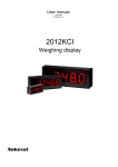
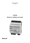
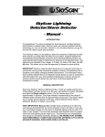
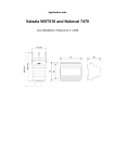
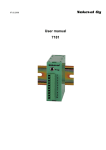
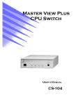
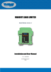
User manual
18.6.2009
Firmware V2.0
2011KCI
2211KCI
Weighing display
INTRODUCTION
2011KCI and 2211KCI are input cards specially
designed for Konecranes. They can be placed in
any of Nokeval E and F series large displays, like
1000F4.
these can be scaled freely, and independently on
each channel.
These models have been superceded by 2012KCI
in spring 2007.
The card provides one (2011KCI) or two (2211KCI)
2-8 V analog input channels. The upper end of
A separate Technical manual is available on
request, covering more details of the KCI displays.
Table of contents
Introduction......................................................................................................................................................2
Ordering...........................................................................................................................................................3
Installing...........................................................................................................................................................4
Operation.........................................................................................................................................................7
User interface...................................................................................................................................................9
Specifications.................................................................................................................................................11
Manufacturer
Tel +358 3 3424800
Fax +358 3 3422066
Nokeval Oy
Yrittäjäkatu 12
FIN-37100 Nokia
Finland
email [email protected]
WWW http://www.nokeval.com
2
ORDERING
Ordering
Obsolete
Name
Voltages
It is recommended to replace the 2011KCI and
2211KCI by more advanced 2012KCI, which has
been available since spring 2007.
-24VDC
24 VDC
-48VAC
48 VDC or VAC
-230VAC
115 or 230 VDC or VAC
Order code
After summer 2009, the input voltage range of the
230 VAC model has been extended to cover the
range 41...265 VDC/AC, removing the need for a
separate 48 VAC model. The voltage options are:
Example: 1000F4 – 2011KCI – 230VAC
The order code consists of several parts. The first
part describes the large display type, the next part
defines the input card type, and the last part
selects the supply voltage.
Large display type
Nokeval has four cases for large field displays.
These are:
575 Five 57 mm digits, plastic enclosure
1000 Three to four 100 mm digits, steel
1100 Five to six 100 mm digits, steel
1800 Three to five 180 mm digits, steel
The letter after the case size is either E or F. This
tells the type of the internal electronics. They are
principally the same but have different looks. The
main difference is that the input card is upside
down in the E chassis. Since beginning of year
2003 all displays have been with F chassis.
Name
Voltages
-24VDC
24 VDC
-48/230VAC
48, 115, or 230 VDC or VAC
Common models
1000F4-2011KCI-48/230VAC: four 100mm digits,
1 input, power 48 to 230 VAC.
1000F4-2211KCI-48/230VAC: four digits, 2 inputs,
power 48 to 230 VAC.
Spare parts ordering
The number after the letter defines the number of
display digits.
Spare input card:
2011KCI-IN
2211KCI-IN
Input card type
Spare electronics unit including input card:
SP-EL2011KCI-48/230VAC (or whichever
supply and cards)
These large displays use Nokeval 2000 series
input cards. Custom input cards 2011KCI and
2211KCI have been designed for KCI.
Spare ribbon cable from el unit to large digits:
SP-CA-EL1000F
Spare large digit:
SP-100DISP (100 mm digit)
Power supply options
Before summer 2009, the large field displays have
been available with three power supply options:
3
INSTALLING
Mounting
Dimensions for 1000F, 1100F, and 1800F:
500, 670 1045
120,130,
210
188,250, 375
147, 210, 330
455, 625, 1025
482, 650, 1030
Opening the case
To access the electrical connections and the small user interface used for configuring the unit, the steel case
has to be opened. First unscrew all the screws surrounding the display, then lift off the black steel frame and
the red plexiglass. Finally unscrew the screw that is located on the right hand side of the rightmost digit. Now
the display assembly may be turned away on its hinges.
Inside the main case
The electronics unit
The electronics unit may be opened or detached from the case. To open it, unscrew the four M3 screws that
are holding the cover on its corners. If the unit has to be detached, unscrew the other screws on its top and
bottom sides. Normally there is no need to open the electronics unit. Caution! Opening the electronics
unit exposes parts carrying lethal voltages on units powered with more than 24 V supply!
4
Supply voltage and earthing
24VDC models
Main case
Earthing
9
8
Electronics unit
7
Power
Power supply
24 VDC.
Any polarity.
Slot C
0.0
Slot B
Slot A
Ribbon cable to the digits
Small display + buttons
Two cable glands
Bring the supply voltage to the connector indicated in the picture. If the supply voltage is more than 24 V, the
enclosure must be reliably earthed using the M4 screw provided. A pre-fuse is not necessary, but if one is
used, it should be at least 2 AT.
48/230VAC models
Main case
Earthing
Electronics unit
N
L
Pow er
Power supply
48, 115, or 230
VAC
Slot C
0.0
Slot B
Slot A
Bring the Live and Neutral wires to the electronics unit as in picture. A pre-fuse is not necessary, but if one is
used, it should be at least 1 AT.
Connect the Protective Earth wire to the M4 screw using the Faston connector provided - a Faston crimping
tool is needed.
For electrical safety, the power and signal wires must be fastened using cable ties or equivalent so that if one
signal wire is detached, it can not touch any of the power supply wires, or vice versa.
5
Signal connections
2011KCI
2211KCI
Slot A
6
Slot A
Flt switch
6
5
Tare switch
5
4
Input (2-8 V)
3
Common
2
1
4
Input 1 (2-8 V)
3
Common
2
Input 2 (2-8 V)
1
Bring the input signal in slot A terminal 4 and its
common in terminal 3.
The 2-8 V analog signals are connected in slot A
terminals 4 (channel 1) and 2 (channel 2). The
common wire is connected in terminal 3.
Connect a potential-free switch between 6 and 3 to
use the ”Flt” function (when the switch is closed,
the display will show ”Flt” instead of the reading).
Connect a potential-free switch between 6 and 3 to
use the Tare function.
Configuring
The display unit may be configured either on the
small display and buttons inside the main case, or
with a programming cable.
access it, both the main case and the electronics
unit cover have to be opened. Removing the
electronics unit cover exposes parts carrying
lethal voltages on units with supply voltage
more than 24 volts!
Inside buttons
Open the main case as explained above. Use the
small display and four buttons to configure the
display unit. Using the buttons is explained in
chapter User interface.
Nokeval provides two alternative programming
cables: "POL-RS232" for RS-232 port, and
"DCS772" for USB port.
Via a programming cable
A free software MekuWin is used, available for
Microsoft Windows. Select SCL protocol, 9600
baud, and address 0 or 126.
In addition, an adapter for the pin header, called
"POL-3PIN", is required.
Using the programming cable is possible only on
models equipped with circuit board ”2012” in slot A.
For the configuration menu contents, refer to the
chapter User interface.
The programming cable is attaced to a pin header
marked "POL" on the input card in slot A. To
6
OPERATION
2011KCI
A/D conv
Calibr
Scaling
Lowpass
Input1
FltSw
Dead
Display
123.4
Flt
Input processing
The input is measured using an analog-to-digital
converter. The reading is scaled to a weighing
reading using the Lo and Hi setting in the
configuration menu. When the input signal is 2.00
V, the display will indicate the Lo value, which is
almost always set to 0. At 8.00 V input, the display
will indicate the Hi value. The measurement unit
can be freely selected (kg, ton, lbs...), and there is
no need for the display unit to know it.
How many digits are displayed after the decimal
point, is defined with the Dec setting in the
configuration menu. The Dec setting can also be
used to show fixed zeros, which is useful when
displaying large readings (e.g. 10000 kg) and the
last digits would otherwise be nervous.
The display can be slowed down with a digital 3rd
degree lowpass filter.
The Dead setting can be used to round small
readings to zero, or to prevent negative readings
Flt switch
The input card 2012KCI has one digital input.
Closing a switch connected to it will make the
display to show "Flt" (except in Remote state).
7
2211KCI
2211KCI input processing
A/D conv
Calibr and
scaling
Prevent
negative
Lowpass
+
>0
Input1
+
-
A/D conv
>0
Tare
Input2
Dead
Display
123.4
TareSw
Each 2 to 8 V input signal is scaled to weighing
reading using the Lo, Hi 1, and Hi 2 settings in the
configuration menu. Lo is almost always 0, and Hi
1 and Hi 2 correspond to the full scale weighs of
the input channels. The unit of the scaling can be
freely selected (kg, ton, lbs...) and there is no need
for the display to know it. Then, negative readings
are prevented (limited to 0), before summing up
the readings. A tare value is subtracted. A new tare
value can be stored using an external switch.
The 3rd order lowpass filter can be used to
attenuate fluctuations and disturbances. The filter
is bypassed a couple of seconds after power-up.
8
USER INTERFACE
This chapter describes how to use the small
display and buttons inside the display unit to
perform configuration. The contents of the
configuration menu is described here too.
that the large display may have less than 6 digits
and then it shows dashes if the content does not
fit.
The displays may be in the following states:
• Normal state – displaying the readings.
• Configuration state – changing the settings.
The small display inside the case and the large
display always show the same contents, except
Normal state
After power-up, the unit is in the normal state,
displaying the input readings according to the
configuration.
The tare function can be used also by pressing the
* key, and the tare value can be reset by pressing
* and > together (2211KCI only).
The A3 indicator LED is lit when the external switch
controlling the FLT or Tare function is active.
Configuration state
Press the * and ^ keys simultaneously two
seconds in the normal state to enter the
configuration state. When entered, the Conf led will
light.
Floating point values, such as scaling and the
lopass filter, are edited with ^v> keys: select digit
to edit (blinking) with > and change it with ^v.
When the decimal point is blinking, it can be
moved with ^v. The first digit can be replaced with
a minus sign.
Navigating
Exiting
Use the ^v keys to browse the menu. To see a
configuration value and possibly edit it, push the >
key. Return to the menu with the * key.
When all settings are done, exit from the
configuration menu with * key. Two options are
shown: Save to keep the settings made, and Undo,
to discard all changes. Select ^v Save or Undo
and push >. (Or push * to get back to the menu.)
Entering
Editing
Integer values, such as the Dec setting, are
adjusted with the ^v keys.
2011KCI configuration menu
Dec
Lo
Hi
Lopass
Number of digits after the decimal point. E.g. with value of 1, the reading is displayed with one
digit after the decimal point.
If the dec setting is negative, the corresponding number of last digits is rounded to zero.
Example: Dec= -2, the display will step 0, 100, 200...
Displayed reading at the minimum input signal (2 V). Almost always 0.
Displayed reading at the maximum input signal (8 V).
Damping, will slow down display fluctuations. Set the time constant (63% of the final change) in
seconds. Fast operation = 0.
9
Dead
Dead zone around zero.
Dead>0: Display readings smaller than Dead are rounded to zero.
Dead=0: Negative readings are prevented.
Dead<0: Both positive and negative readings are displayed.
2211KCI configuration menu
Dec
Lo
Hi 1
Hi 2
Lopass
Dead
Number of digits after the decimal point. E.g. with value of 1, the reading is displayed with one
digit after the decimal point.
If the dec setting is negative, the corresponding number of last digits is rounded to zero.
Example: Dec= -2, the display will step 0, 100, 200...
Offset that is added to the display reading. May be negative. Almost always 0.
Displayed reading at the maximum input signal on channel 1.
Displayed reading at the maximum input signal on channel 2. When there is a signal on both
channels, the sum is displayed.
Damping, will slow down display fluctuations. Set the time constant (63% of the final change) in
seconds. Fast operation = 0.
Dead zone around zero.
Dead>0: Display readings smaller than Dead are rounded to zero.
Dead=0: Negative readings are prevented.
Tare
Dead<0: Both positive and negative readings are displayed.
Tare value that is subtracted from every reading. Mainly for viewing, but can be edited too.
10
SPECIFICATIONS
Analog inputs 2011KCI/2211KCI
Nominal signal
Measmt range
Calibr accuracy
Thermal drift
Overvolt protect
Overvolt category
2 to 8 VDC
-1…11 V or wider
±5 mV
±1 mV/°C
±32 VDC/VAC line-to-line
Not rated; analog and digital
inputs must not be connected
Max cable length
Sample rate
to a voltage more than 50
VAC or 120 VDC with respect
to ground.
30 m
4 Hz each channel
Power supplies
24VDC model
Nominal voltage
Voltage range
Power
Pre-fuse
48/230VAC model
24 VDC
20.4…32 VDC
<15 W
≥2 AT; not required
Nominal voltage
Voltage range
Frequency
Power
Pre-fuse
Protection
48, 115, or 230 VAC
41…265 VAC or VDC
45…65 Hz
<25 W
≥1 AT; not required
Class 1
See chapter Installing
Protection
IP65
Enclosure
Dimensions
Regulations
EMC immunity EN 61326
ESD
EM field
Burst
Surge
Conducted RF
Electrical safety EN 61010-1
61000-4-2, 4 kV contact,
criterion B
61000-4-3, 10 V/m, criterion
A; analog inputs may deflect
0.1% of range
61000-4-4, any port: 2 kV,
criterion B
61000-4-5, power supply: 1 kV
line-to-line, 2 kV line-toground, criterion A
61000-4-5, signal ports: not
applied (short-distance wires)
61000-4-6, any port: 10 V,
criterion A; analog inputs may
deflect 0.1% of range
EMC emission EN 61326
RF emissions
AC mains
CISPR 16 class A
CISPR 16 class A
11