1
RSLogix 5000
Fuzzy Designer
User Manual
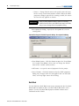
www.klinkmann.com
8 / 2011
www.klinkmann.com
Important User Information
Solid state equipment has operational characteristics differing from those of
electromechanical equipment. Safety Guidelines for the Application,
Installation and Maintenance of Solid State Controls (publication SGI-1.1
available from your local Rockwell Automation sales office or online at
http://literature.rockwellautomation.com) describes some important
differences between solid state equipment and hard-wired electromechanical
devices. Because of this difference, and also because of the wide variety of
uses for solid state equipment, all persons responsible for applying this
equipment must satisfy themselves that each intended application of this
equipment is acceptable.
In no event will Rockwell Automation, Inc. be responsible or liable for
indirect or consequential damages resulting from the use or application of
this equipment.
The examples and diagrams in this manual are included solely for illustrative
purposes. Because of the many variables and requirements associated with
any particular installation, Rockwell Automation, Inc. cannot assume
responsibility or liability for actual use based on the examples and diagrams.
No patent liability is assumed by Rockwell Automation, Inc. with respect to
use of information, circuits, equipment, or software described in this manual.
Reproduction of the contents of this manual, in whole or in part, without
written permission of Rockwell Automation, Inc., is prohibited.
Throughout this manual, when necessary, we use notes to make you aware
of safety considerations.
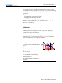
WARNING
IMPORTANT
ATTENTION
Identifies information about practices or circumstances that can cause
an explosion in a hazardous environment, which may lead to personal
injury or death, property damage, or economic loss.
Identifies information that is critical for successful application and
understanding of the product.
Identifies information about practices or circumstances that can lead
to personal injury or death, property damage, or economic loss.
Attentions help you identify a hazard, avoid a hazard, and recognize
the consequence
SHOCK HAZARD
Labels may be on or inside the equipment, for example, a drive or
motor, to alert people that dangerous voltage may be present.
BURN HAZARD
Labels may be on or inside the equipment, for example, a drive or
motor, to alert people that surfaces may reach dangerous
temperatures.
Allen-Bradley, ControlLogix, RSLogix 5000, Logix, and RSLinx are trademarks of Rockwell Automation, Inc.
Trademarks not belonging to Rockwell Automation are property of their respective companies.
8 / 2011
www.klinkmann.com
Table of Contents
Preface
About This Publication. . . . . . . . . . . . . . . . . . . . . . . . . . . . . 7
Who Should Use This Publication. . . . . . . . . . . . . . . . . . . . . 7
Conventions . . . . . . . . . . . . . . . . . . . . . . . . . . . . . . . . . . . . 7
Chapter 1
Get Started with FuzzyDesigner
Introduction . . . . . . . . . . . . . . . . . . . . . . . . . . . . . . .
Understanding FuzzyDesigner . . . . . . . . . . . . . . . . . .
Fuzzy Logic and Fuzzy Control Essentials . . . . . . .
Potential Use of Fuzzy Logic . . . . . . . . . . . . . . . . .
Specifications and Features . . . . . . . . . . . . . . . . . .
Integrated Design Environment (IDE) screen captures .
.
.
.
.
.
.
.
.
.
.
.
.
.
.
.
.
.
.
.
.
.
.
.
.
.
.
.
.
.
.
9
9
12
16
18
22
Chapter 2
FuzzyDesigner Component Library Introduction . . . . . . . . . . . . . . . . . . . . . . . . . . . . . . . . . . . . 29
Component Interface . . . . . . . . . .
Library of Components. . . . . . . . .
Supported Membership Functions.
Input Port . . . . . . . . . . . . . . . . . .
User Defined Filter . . . . . . . . .
Butterworth Low Pass Filter . .
Connections . . . . . . . . . . . . . .
Parameters . . . . . . . . . . . . . . .
Input Linguistic Variable. . . . . . . .
Connections . . . . . . . . . . . . . .
Parameters . . . . . . . . . . . . . . .
Output Linguistic Variable . . . . . .
Defuzzification . . . . . . . . . . . .
Connections . . . . . . . . . . . . . .
Parameters . . . . . . . . . . . . . . .
Output Takagi-Sugeno Variable . .
Connections . . . . . . . . . . . . . .
Parameters . . . . . . . . . . . . . . .
Intermediate Linguistic Variable . .
Connections . . . . . . . . . . . . . .
Parameters . . . . . . . . . . . . . . .
Rule Block. . . . . . . . . . . . . . . . . .
Supported Format of Rules . . .
Connections . . . . . . . . . . . . . .
Parameters . . . . . . . . . . . . . . .
PID Controller . . . . . . . . . . . . . . .
Connections . . . . . . . . . . . . . .
Parameters . . . . . . . . . . . . . . .
Output Port . . . . . . . . . . . . . . . . .
Connections . . . . . . . . . . . . . .
Parameters . . . . . . . . . . . . . . .
.
.
.
.
.
.
.
.
.
.
.
.
.
.
.
.
.
.
.
.
.
.
.
.
.
.
.
.
.
.
.
.
.
.
.
.
.
.
.
.
.
.
.
.
.
.
.
.
.
.
.
.
.
.
.
.
.
.
.
.
.
.
.
.
.
.
.
.
.
.
.
.
.
.
.
.
.
.
.
.
.
.
.
.
.
.
.
.
.
.
.
.
.
.
.
.
.
.
.
.
.
.
.
.
.
.
.
.
.
.
.
.
.
.
.
.
.
.
.
.
.
.
.
.
.
.
.
.
.
.
.
.
.
.
.
.
.
.
.
.
.
.
.
.
.
.
.
.
.
.
.
.
.
.
.
.
.
.
.
.
.
.
.
.
.
.
.
.
.
.
.
.
.
.
.
.
.
.
.
.
.
.
.
.
.
.
.
.
.
.
.
.
.
.
.
.
.
.
.
.
.
.
.
.
.
.
.
.
.
.
.
.
.
.
.
.
.
.
.
.
.
.
.
.
.
.
.
.
.
.
.
.
.
.
.
.
.
.
.
.
.
.
.
.
.
.
.
.
.
.
.
.
.
.
.
.
.
.
.
.
.
.
.
.
.
.
.
.
.
.
.
.
.
.
.
.
.
.
.
.
.
.
.
.
.
.
.
.
.
.
.
.
.
.
.
.
.
.
.
.
.
.
.
.
.
.
.
.
.
.
.
.
.
.
.
.
.
.
.
.
.
.
.
.
.
.
.
.
.
.
.
.
.
.
.
.
.
.
.
.
.
.
.
.
.
.
.
.
.
.
.
.
.
.
.
.
.
.
.
.
.
.
.
.
.
.
.
.
.
.
.
.
.
.
.
.
.
.
.
.
.
.
.
.
.
.
.
.
.
.
.
.
.
.
.
.
.
.
.
.
.
.
.
.
.
.
.
.
.
.
.
.
.
.
.
.
.
.
.
.
.
.
.
.
.
.
.
.
.
.
.
.
.
.
.
.
.
.
.
.
.
.
.
.
.
.
.
.
.
.
.
.
.
.
.
.
.
.
.
.
.
.
.
.
.
.
.
.
.
.
.
.
.
.
.
.
.
.
.
.
.
.
.
.
.
.
.
.
.
.
.
.
.
.
.
.
.
.
.
.
.
.
.
.
.
.
.
.
.
.
.
.
.
.
.
.
.
.
.
.
.
.
.
.
.
.
.
.
.
.
.
.
.
.
.
.
.
.
.
.
.
.
.
.
.
.
.
.
.
.
.
.
.
.
.
.
.
.
.
.
.
.
.
.
.
.
.
.
.
.
.
.
.
.
.
.
.
.
.
.
.
.
.
.
.
.
.
.
.
.
.
.
.
.
.
.
.
.
.
.
.
.
.
.
.
.
.
.
.
.
.
.
.
.
.
.
.
.
.
.
29
30
30
32
33
33
33
34
34
36
36
36
37
42
42
42
45
46
46
47
47
47
48
52
52
52
55
56
56
56
56
8 / 2011
www.klinkmann.com
4
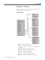
Chapter 3
FuzzyDesigner Graphical User
Interface
Introduction. . . . . . . . . . . . . .
Setting Options . . . . . . . . . . .
Tool Bar. . . . . . . . . . . . . .
FuzzyDesigner Control Basics.
Main Menu . . . . . . . . . . . . . .
.
.
.
.
.
.
.
.
.
.
.
.
.
.
.
.
.
.
.
.
.
.
.
.
.
.
.
.
.
.
.
.
.
.
.
.
.
.
.
.
.
.
.
.
.
.
.
.
.
.
.
.
.
.
.
.
.
.
.
.
.
.
.
.
.
.
.
.
.
.
.
.
.
.
.
.
.
.
.
.
.
.
.
.
.
.
.
.
.
.
.
.
.
.
.
.
.
.
.
.
.
.
.
.
.
.
.
.
.
.
57
57
58
59
60
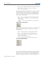
Introduction. . . . . . . . . . . . . . . . . . . . . . . . .
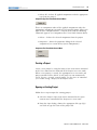
Working with Projects . . . . . . . . . . . . . . . . .
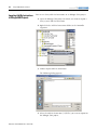
Creating a Project . . . . . . . . . . . . . . . . . .
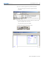
Opening an Existing Project . . . . . . . . . .
Changing the Active Project . . . . . . . . . .
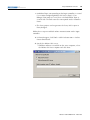
Project Information . . . . . . . . . . . . . . . . .
Saving a Project . . . . . . . . . . . . . . . . . . .
Closing a Project. . . . . . . . . . . . . . . . . . .
Designing a Project. . . . . . . . . . . . . . . . .
Printing a Project . . . . . . . . . . . . . . . . . .
Designing a Fuzzy System . . . . . . . . . . . . . .
Fuzzy System Project Window. . . . . . . . .
Working with Blocks . . . . . . . . . . . . . . .
Working with Text . . . . . . . . . . . . . . . . .
Fuzzy System Components . . . . . . . . . . . . . .
Input Port. . . . . . . . . . . . . . . . . . . . . . . .
Input Linguistic Variable . . . . . . . . . . . . .
Output Port . . . . . . . . . . . . . . . . . . . . . .
Output Linguistic Variable . . . . . . . . . . . .
Output Takagi-Sugeno Variable . . . . . . . .
Intermediate Linguistic Variable. . . . . . . .
Rule Block . . . . . . . . . . . . . . . . . . . . . . .
PID Controller . . . . . . . . . . . . . . . . . . . .
Term Editor . . . . . . . . . . . . . . . . . . . . . . . . .
Term Properties Dialog . . . . . . . . . . . . . . . .
Rule Editor . . . . . . . . . . . . . . . . . . . . . . . . .
Operations with Rules. . . . . . . . . . . . . . .
Rule Editor Tool Bar . . . . . . . . . . . . . . . .
Port Order Editor . . . . . . . . . . . . . . . . . . . . .
Watch . . . . . . . . . . . . . . . . . . . . . . . . . . . . .
History Graph . . . . . . . . . . . . . . . . . . . . . . .
History Graph Control – Context Menu . .
History Graph Control – Tool Bar . . . . . .
History Graph Control – Mouse Dragging
2D Graph . . . . . . . . . . . . . . . . . . . . . . . . . .
2D Graph Control – Context Menu . . . . .
2D Graph Control – Tool Bar . . . . . . . . .
3D Graph . . . . . . . . . . . . . . . . . . . . . . . . . .
3D Graph Control – Context Menu . . . . .
.
.
.
.
.
.
.
.
.
.
.
.
.
.
.
.
.
.
.
.
.
.
.
.
.
.
.
.
.
.
.
.
.
.
.
.
.
.
.
.
.
.
.
.
.
.
.
.
.
.
.
.
.
.
.
.
.
.
.
.
.
.
.
.
.
.
.
.
.
.
.
.
.
.
.
.
.
.
.
.
.
.
.
.
.
.
.
.
.
.
.
.
.
.
.
.
.
.
.
.
.
.
.
.
.
.
.
.
.
.
.
.
.
.
.
.
.
.
.
.
.
.
.
.
.
.
.
.
.
.
.
.
.
.
.
.
.
.
.
.
.
.
.
.
.
.
.
.
.
.
.
.
.
.
.
.
.
.
.
.
.
.
.
.
.
.
.
.
.
.
.
.
.
.
.
.
.
.
.
.
.
.
.
.
.
.
.
.
.
.
.
.
.
.
.
.
.
.
.
.
.
.
.
.
.
.
.
.
.
.
.
.
.
.
.
.
.
.
.
.
.
.
.
.
.
.
.
.
.
.
.
.
.
.
.
.
.
.
.
.
.
.
.
.
.
.
.
.
.
.
.
.
.
.
.
.
.
.
.
.
.
.
.
.
.
.
.
.
.
.
.
.
.
.
.
.
.
.
.
.
.
.
.
.
.
.
.
.
.
.
.
.
.
.
.
.
.
.
.
.
.
.
.
.
.
.
.
.
.
.
.
.
.
.
.
.
.
.
.
.
.
.
.
.
.
.
.
.
.
.
.
.
.
.
.
.
.
.
.
.
.
.
.
.
.
.
.
.
.
.
.
.
.
.
.
.
.
.
.
.
.
.
.
.
.
.
.
.
.
.
.
.
.
.
.
.
.
.
.
.
.
.
.
.
.
.
.
.
.
.
.
.
.
.
.
.
.
.
.
.
.
.
.
.
.
.
.
.
.
.
.
.
.
.
.
.
.
.
.
.
.
.
.
.
.
.
.
.
.
67
67
69
69
70
70
71
71
72
72
72
73
73
75
75
76
79
82
84
88
92
94
97
102
105
108
109
110
113
113
117
119
121
122
122
124
125
125
128
Chapter 4
FuzzyDesigner Projects
8 / 2011
www.klinkmann.com
5
3D Graph Control – Tool Bar . . . . . . . . . . . . . . . . . . . . 130
3D Graph Control – Mouse Dragging . . . . . . . . . . . . . . 130
Chapter 5
Fuzzy System Simulation
Introduction . . . . . . . . . . . . . . . . . . . . . . . . . . . . . . . . . . . 131
Chapter 6
RSLogix 5000 Add-On Instruction
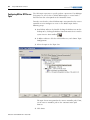
Introduction . . . . . . . . . . . . . . . . . . . . . . . . . . . . . . . .
Generating a Fuzzy Add-On Instruction . . . . . . . . . . . .
Add-On Instruction Parameters . . . . . . . . . . . . . . . .
Importing Add-On Instructions to RSLogix 5000 Projects
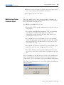
Monitoring and Updating a Project Online . . . . . . . . . .
Configuring RSLinx OPC Server Topic. . . . . . . . . . . . . .
Modifying Fuzzy System Parameters Online . . . . . . . . .
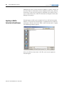
Importing an Add-On Instruction to FuzzyDesigner. . . .
.
.
.
.
.
.
.
.
.
.
.
.
.
.
.
.
.
.
.
.
.
.
.
.
133
134
135
136
138
144
145
146
Chapter 7
XML Format of a Fuzzy Project
Prolog . . . . . . . . . . . . . . . . . . . . . . . . . . . . . . . . . . . . . . . . 147
Document Element . . . . . . . . . . . . . . . . . . . . . . . . . . . . . . 147
Chapter 8
Glossary
Introduction . . . . . . . . . . . . . . . . . . . . . . . . . . . . . . . . . . . 149
8 / 2011
6
www.klinkmann.com
8 / 2011
Preface
www.klinkmann.com
About This Publication
Use this manual to understand how to best use the features in RSLogix
5000 software version 16, FuzzyDesigner.
This manual describes the necessary tasks to:
• build fuzzy systems as block diagrams from components of the
FuzzyDesigner Component Library and use FuzzyDesigner
functions to complete the project.
• use, execute, and monitor the designed fuzzy system on
Rockwell Automation Logix5000 controllers.
• understand the fuzzy project, and how you can export it to the
XML format.
Who Should Use This
Publication
This manual is for application and control engineers, to enhance
functionality of control and decision making systems.
Conventions
7
Text that is
Identifies
Bold
A value that you must enter exactly as shown
Italic
A variable that you replace with your own text or value
Courier
Example programming code, shown in a monospace font so
you can identify each character and space
Enclosed in brackets
A keyboard key
Publication LOGIX-UM004A-EN-P - March 2007
8
Preface
Notes:
Publication LOGIX-UM004A-EN-P - March 2007
8 / 2011
www.klinkmann.com
Chapter
8 / 2011
www.klinkmann.com
1
Get Started with FuzzyDesigner
Introduction
Understanding
FuzzyDesigner
Topic
Page
Understanding FuzzyDesigner
9
Fuzzy Logic and Fuzzy Control Essentials
12
Specifications and Features
18
FuzzyDesigner is a software package for designing a fuzzy system to
be implemented as a Hierarchical Fuzzy System (HFS). Fuzzy systems
can be used in the following applications:
•
•
•
•
Industrial automation and control systems
Process diagnostics and intelligent monitoring systems
Artificial intelligence
Decision-making and forecasting
Hierarchical Fuzzy System
FuzzyDesigner enables application and control engineers to enhance
the functionality of control and decision making systems in various
branches of industry.
FuzzyDesigner includes a library of components you can use to
design a fuzzy system that includes nonlinear input-output mapping.
You can use a hierarchical structure to decompose a complex fuzzy
system into smaller and simpler parts. This reduces the internal
complexity of a fuzzy model and results in fewer fuzzy rules and
provides easier insight into the system operation.
9
Publication LOGIX-UM004A-EN-P - March 2007
10
8 / 2011
Get Started with FuzzyDesigner
www.klinkmann.com
FuzzyDesigner is designed to work with Rockwell Automation's
Logix5000 family of controllers. A fuzzy system designed in
FuzzyDesigner can be exported to an L5X Add-On instruction (AOI)
format. You can then import the fuzzy AOI into any of your projects
as needed. Fuzzy AOIs can be used by any of the programming
languages (Function Block Diagram, Ladder Logic, or Structured Text).
With FuzzyDesigner, you can also monitor and update the selected
fuzzy AOI online, directly in the running controller. This is made
available through the RSLinx OPC Server.
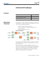
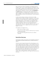
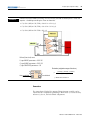
The Intended Use of FuzzyDesigner figure shows the underlying idea
and intended use of the FuzzyDesigner software package used in
designing Fuzzy Add-On Instructions for Logix applications. You can
build smart components, based on the expert knowledge encoded in
fuzzy If-Then rules. You can use these components in the many
applications listed above.
Intended Use of FuzzyDesigner
Publication LOGIX-UM004A-EN-P - March 2007
8 / 2011
Get Started with FuzzyDesigner
www.klinkmann.com
11
A Fuzzy Add-On instruction does not typically compete against
standard controls found in Proportional-Integral-Derivative Controllers
(PID). Fuzzy logic is a complementary tool, and fills functional gaps
not addressed in standard controllers such as PIDs or Model Predictive
Controllers.
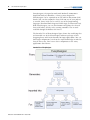
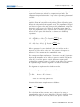
A development cycle of fuzzy logic solutions for Logix applications
consists of multiple steps.
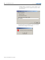
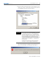
1. Design the fuzzy system in FuzzyDesigner.
2. Generate the fuzzy Add-On Instruction.
3. Integrate (import and instantiate) the fuzzy AOI to your RSLogix
5000 project.
4. Monitor and tune the fuzzy AOI running in Logix online by
using FuzzyDesigner.
Using FuzzyDesigner with RSLogix 5000 Software
n
p
o
q
If you are unfamiliar with fuzzy logic, the next section introduces
fuzzy logic terms and principles you might use in your fuzzy system.
Publication LOGIX-UM004A-EN-P - March 2007
12
8 / 2011
Get Started with FuzzyDesigner
www.klinkmann.com
Fuzzy Logic and Fuzzy Control Essentials
This section introduces basic concepts used in a Fuzzy Add-On
Instruction. The designer should know how to deal with an
instruction’s inputs, outputs, and fuzzy If-Then rules that will be used
to define input-output mapping.
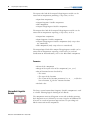
There are quite a number of systems or processes that are highly
nonlinear, not well understood from the formal description point of
view, or for which a mathematical model is not readily available. For
these systems or processes, there is often an expert that is capable of
supervising or controlling the process in a satisfactory manner. The
figure Nonlinear System Example illustrates the difference between
linear and nonlinear systems.
Nonlinear System Example
The decision making the expert uses in control system supervision
can be expressed as a set of Fuzzy Logic If-Then rules.
Publication LOGIX-UM004A-EN-P - March 2007
8 / 2011
Get Started with FuzzyDesigner
www.klinkmann.com
13
An expert may be an operator, a maintenance person, or a control
engineer, who knows what adjustments are needed during process
instability. These adjustments may include defining setpoints for
process variables, defining control action in feedforward or feedback
contro,l or setting gains of conventional controllers, and may be as
simple as turning a valve or knob.
Rockwell Automation is introducing a tool for building smart
instructions that encode If-Then rules and use fuzzy logic internally to
describe vague and incomplete knowledge in a natural way. Fuzzy
Logic may serve in situations where:
• the process has not been automated and is running in Manual
mode.
• a well-tuned PID controller does not provide the desired
response, however, the expert knowledge is available to define
the rules for a fuzzy algorithm.
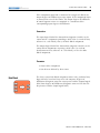
Let’s look at an example where we will discuss building a Heat,
Ventilation and Air Conditioning (HVAC) system that manipulates the
compressor speed based on room temperature and humidity. In HVAC
systems, room comfort is often associated with vague (fuzzy) values of
temperature and humidity that are more suitable for describing the
problem than numerical (crisp) values.
Fuzzy rules used in this example might be as follows.
If
Then
Temperature is high and humidity is
high
Speed is medium
Temperature is medium and humidity
is very high
Speed is high
Consider these factors when developing fuzzy rules:
• How do I specify High and other fuzzy values in fuzzy rules?
• How do the rules process numerical inputs provided by tags
associated with sensors?
• How do the rules derive outputs from inputs?
• If the output generated is vague (fuzzy), how do I get the
numerical (crisp) value at the output when needed?
Publication LOGIX-UM004A-EN-P - March 2007
14
8 / 2011
Get Started with FuzzyDesigner
www.klinkmann.com
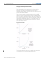
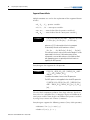
Crisp and Fuzzy
For temperature readings, you can classify a reading into three sets,
Low, Medium and High. Each set contains values in a given interval,
and the intervals do not overlap. This means that a single reading or
value is uniquely classified into one set.
degree of membership
(level of classification)
Low
Medium
High
Classification
Result
1
1.00 Medium
0
0.0 High
0.0 Low
range
20
150
temperature
Crisp Value
TIP
Degree of membership (DOM) is a value describing how well
the particular value of the variable (in this case, temperature)
fits the meaning of the label of the set, Medium. If the DOM is
1, the current temperature is understood as 100% Medium.
However, vague classifications are more realistic as there is usually no
sharp border between Low, Medium, or High temperatures. In this
situation, however, a single numerical value might fall into multiple
categories. For example, it might be partially Medium, and partially
High as shown in the following figure. A specification of how much
the particular value of temperature fits into the meaning of the label of
the category (fuzzy set) is described by the membership function,
which becomes a design parameter of the fuzzy controller.
Publication LOGIX-UM004A-EN-P - March 2007
8 / 2011
Get Started with FuzzyDesigner
www.klinkmann.com
15
Similar fuzzy terms are designed for the output variables, that is, Low,
Medium, and High for compressor speed in our example.
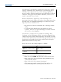
Fuzzy rules
The way in which the classified inputs are treated when passing
through rules is shown in the following figure for our compressor
control example.
Publication LOGIX-UM004A-EN-P - March 2007
16
8 / 2011
Get Started with FuzzyDesigner
www.klinkmann.com
First, the numerical values of Temperature and Humidity get their
meaning. In our case, the current setting of the Temperature is such
that it is both 85% Medium and 40% High. Humidity is both 80% High
and 50% Very High. The first rule is thus 80% true for the current
inputs while the second rule is 40% true when using minimum for
the and operation. The first rule states that, if 100% satisfied, the
compressor should run at Medium speed. Currently, the first rule is
only 80% fulfilled, so one method of how to consider that the rule is
only 80% fulfilled is to truncate the Medium fuzzy set for the output at
the level 0.8.
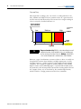
A similar situation happens with the second rule where High
compressor speed is only 40% fulfilled. As both rules are used at the
same time, their conclusions must be combined to get a fuzzy value
for the output, which is compressor speed. The partially-fulfilled
Medium and High fuzzy sets are unified, and a single fuzzy value is
assigned to Compressor Speed. As conventional control systems
cannot deal with fuzzy values, the fuzzy instruction includes
conversion from a fuzzy to a crisp value. For this case, the center of
gravity for the green area is computed and used to represent the
original fuzzy value.
To summarize, the designer has to:
• define input and output variables.
• cover the interval of the respective variable by fuzzy sets (that is,
membership functions).
• write if-then rules using labels of the fuzzy sets defined
previously.
Potential Use of Fuzzy Logic
FuzzyDesigner enables you to enhance the functionality of existing or
new control and decision making systems in various branches of
industry.
The fuzzy system designed and generated by FuzzyDesigner can be
used in control systems, for example, as a direct nonlinear fuzzy-rule
based controller, PID-feedback control system supervisor, or a process
model in a Model Predictive Control scheme. Input and output filters
are used for signal preprocessing such as filtering, deriving trends, and
many other functions that might add dynamics to the static I/O map
generated from fuzzy rules. Input filters can also be designed in
FuzzyDesigner. Output filtering is an option and contains, for
instance, a discrete integrator fed by the output of the Fuzzy Add-On
Instruction.
Publication LOGIX-UM004A-EN-P - March 2007
8 / 2011
Get Started with FuzzyDesigner
www.klinkmann.com
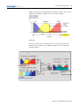
17
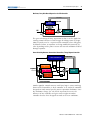
Nonlinear, Fuzzy Rule Based Supervisor of a PID Controller
Plant States
feedforward
FUZZY
FUZZY
SUPERVISOR
SUPERVISOR
PID
gains
SP
CV
PID
PID
CONTROLLER
CONTROLLER
PLANT
PLANT
PV
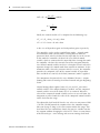
The great advantage of fuzzy supervision is that it can be applied to
existing control and there is little danger of making errors in design.
Most frequently used is a supervised PID controller where PID gains,
feedforward action, or setpoints are being modified dynamically by
rules depending on the process status and external conditions defined
through setpoints.
Smart Switching Between Conventional Controllers, Takagi-Sugeno Controller
Plant State
FUZZY
FUZZY SUPERVISOR
SUPERVISOR
Schedule weights ∈ [0,1]
CONTROLLER
CONTROLLER
11
Setpoints
CONTROLLER
CONTROLLER
22
CONTROLLER
CONTROLLER
33
×
+ CV
×
+
PLANT
PLANT
+
×
Process Variables
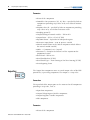
Another popular control structure with fuzzy logic is smart switching
between local controllers. A local controller is an analytical controller
designed to work around specific process operation conditions. Once
the conditions change, the rule based supervisor decreases the
influence of one controller and gives more weight to another
controller that has been designed to work in the new conditions.
Publication LOGIX-UM004A-EN-P - March 2007
18
8 / 2011
Get Started with FuzzyDesigner
www.klinkmann.com
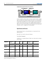
Feedback Control System with Direct Fuzzy Controller
Control system status
Primary controls
Setpoints
FUZZY
CONTROLLER
Input filter
Control
Variables
PLANT
PLANT
Output filter
Process Variables
A fuzzy controller with the above structure typically handles multiple
inputs and generates multiple outputs. This system is recommended
for experienced designers since control variables are direct functions
of rules. The number of rules increases rapidly with the number of
inputs and fuzzy terms for inputs. The problem of dimensionality can,
however, be reduced by hierarchical structuring of the rule base of the
controller, which is supported by FuzzyDesigner.
Specifications and Features
FuzzyDesigner features and specifications are summarized in the
following tables.
For details, refer to the subsequent chapters.
Fuzzy System Components
Components are graphical objects, blocks you work with, to design a
fuzzy system.
Component
Membership
functions
AND
OR
Aggregation
Inference
(Activation)
Defuzzification
Max s-norm
Mamdani/ Fuzzy
Arithmetic
CA/MCA/
MOM/SOM/ LOM
Type/method if applicable
Input Port
Input Linguistic
Variable
Trapezoidal,
S-shape, and their
inverses
Rule Block
Output
Linguistic
Variable
Min/product
t-norms
Trapezoidal,
singleton
Output Port
Publication LOGIX-UM004A-EN-P - March 2007
Max
8 / 2011
Get Started with FuzzyDesigner
www.klinkmann.com
Component
Membership
functions
AND
OR
Aggregation
Inference
(Activation)
19
Defuzzification
Type/method if applicable
Intermediate
Linguistic
Variable
Max s-norm
Output T-S
Variable
Max s-norm
PID Controller
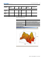
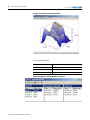
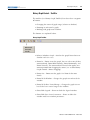
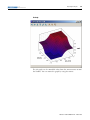
Fuzzy System Analysis Tools
Tool
Description
2D/3D mesh plots
Visualization of input-output static mappings generated
by the fuzzy system or its specified subsystem
Interactive plot control
Color, grid, texture, zoom, and viewpoint management
Tracing fuzzy system evaluation
Marks output on the mesh when input is being changed
FuzzyDesigner Mesh Plot
Publication LOGIX-UM004A-EN-P - March 2007
20
8 / 2011
Get Started with FuzzyDesigner
www.klinkmann.com
FuzzyDesigner Mesh Plot with Simulated Path
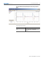
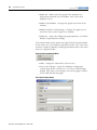
Fuzzy System Monitoring
Feature
Description
Numerical and graphical display
Monitoring of all internal variables
Archiving
Recording specified internal or external variables
History graph
Plotting history graph for on-line or off-line monitoring
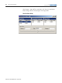
Fuzzy System Monitoring Through Numerical Displays
Publication LOGIX-UM004A-EN-P - March 2007
8 / 2011
Get Started with FuzzyDesigner
www.klinkmann.com
21
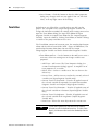
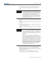
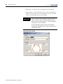
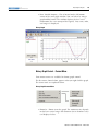
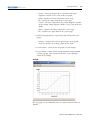
Fuzzy System Monitoring Through Plotting Historical Recordings and On-Line
Update
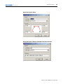
FuzzyDesigner Project Formats
File Format
Description
XML
.FSP – complete project file generated by
FuzzyDesigner, .XML – user-supplied fuzzy system or
project file
Publication LOGIX-UM004A-EN-P - March 2007
22
8 / 2011
Get Started with FuzzyDesigner
www.klinkmann.com
Direct Support of Logix5000 controllers
FuzzyDesigner, version 16.00 and later, supports Rockwell
Automation's Logix5000 family of controllers. The fuzzy system
designed using FuzzyDesigner can be exported to an RSLogix 5000
Add-On Instruction (AOI) XML import file. You can then import the
fuzzy system into any of your projects as needed. Fuzzy AOI can be
used by any of the programming languages (Function Block Diagram,
Ladder Logic, or Structured Text). With FuzzyDesigner, you can also
monitor and update the selected fuzzy AOI online, directly in the
running controller. This is made available through RSLinx OPC Server.
Features
Description
Export fuzzy AOI
Utility for export of designed fuzzy system into L5X file.
On-line parameter change
Changing parameters of a fuzzy system downloaded to the controller
dynamically is enabled.
Real-time fuzzy system monitoring
Exact copy of the fuzzy system running on the PLC allows FuzzyDesigner to
monitor all internal variables on the computer when both copies are fed with
the identical inputs.
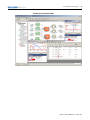
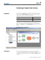
Integrated Design
Environment (IDE) screen
captures
Publication LOGIX-UM004A-EN-P - March 2007
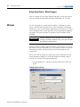
Some of the FuzzyDesigner features, summarized in the preceding
tables, are shown in this section.
8 / 2011
Get Started with FuzzyDesigner
www.klinkmann.com
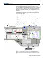
23
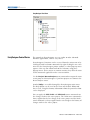
FuzzyDesigner Environment in Brief
Publication LOGIX-UM004A-EN-P - March 2007
24
8 / 2011
Get Started with FuzzyDesigner
www.klinkmann.com
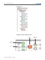
Project Tree view
FuzzyDesigner Environment - Component examples
Rule Block
Input Linguistics
Variable
Input Port
Publication LOGIX-UM004A-EN-P - March 2007
Output Liguistics
Variable
8 / 2011
Get Started with FuzzyDesigner
www.klinkmann.com
25
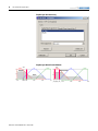
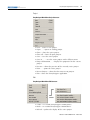
FuzzyDesigner Membership Functions
Term Editor
Degree of
Fulfillment
window
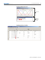
FuzzyDesigner Rule Base - Rule Editor
Publication LOGIX-UM004A-EN-P - March 2007
26
8 / 2011
Get Started with FuzzyDesigner
www.klinkmann.com
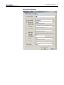
FuzzyDesigner Rule Interfacing
FuzzyDesigner Defuzzification Methods
DOF(negative) is maximal
DOF(negative)
DOF(zero)
y*
y*
(MCA) (CA)
Publication LOGIX-UM004A-EN-P - March 2007
y*
y*
y*
(SOM) (MOM) (LOM)
8 / 2011
Get Started with FuzzyDesigner
www.klinkmann.com
27
FuzzyDesigner PID Controller
Publication LOGIX-UM004A-EN-P - March 2007
28
Get Started with FuzzyDesigner
Notes:
Publication LOGIX-UM004A-EN-P - March 2007
8 / 2011
www.klinkmann.com
Chapter
8 / 2011
www.klinkmann.com
2
FuzzyDesigner Component Library
Introduction
Component Interface
The FuzzyDesigner Component Library offers eight components from
which you can efficiently build distributed fuzzy systems.
Topic
Page
Component Interface
29
Library of Components
30
Supported Membership Functions
30
Input Port
32
Input Linguistic Variable
34
Output Linguistic Variable
36
Output Takagi-Sugeno Variable
42
Intermediate Linguistic Variable
46
Rule Block
47
PID Controller
52
Output Port
56
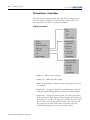
The connection between components is called a link. Generally, a
Hierarchical Fuzzy System (HFS) computes with data in the form of a
crisp (real) value and/or a fuzzy set. Not all components enable both
types of data to be transferred over the link. The data type on both
ends of a link should match. FuzzyDesigner uses icons to define a link
type as follows.
FuzzyDesigner Icons
Icon
Description
Crisp value (input or output value link) – input crisp values and crisp values
resulting from defuzzification are transferred over the link
Crisp value (input or output value link) – crisp values are transferred over
the link
DOF value (input or output logical link) – degrees of fulfillment of fuzzy
terms of a fuzzy variable are transferred over the link to a rule block
DOF value (input or output logical link) – degrees of fulfillment of fuzzy
terms resulting from rule block evaluation are transferred over the link to a
fuzzy variable
29
Publication LOGIX-UM004A-EN-P - March 2007
30
8 / 2011
FuzzyDesigner Component Library
Library of Components
www.klinkmann.com
The FuzzyDesigner Component Library offers the following
components from which you can assemble fuzzy systems ranging
from single input – single output systems to multiple input – multiple
output systems with complex hierarchical structure of rules.
FuzzyDesinger Component Library Icons
Icon
Supported Membership
Functions
Publication LOGIX-UM004A-EN-P - March 2007
Name
Description
Input Port
Preprocesses and stores values of a fuzzy
system’s input variables.
Output Port
Stores values of a fuzzy system’s output
variables.
Input Linguistic
Variable
Stores linguistic terms and is used for
classification of the actual component input,
represented by a crisp value, into the fuzzy sets
defined for the respective linguistic terms. In
fuzzy control, the process where the input is
converted from a crisp value is commonly called
fuzzification.
Rule Block
Stores rules and computes degree of fulfillment
of rule conditions .
Intermediate
Linguistic
Variable
Bridges logical chaining of rule blocks.
Output Linguistic
Variable
Stores linguistic terms and computes the output
value from degrees of fulfillment of stored terms
(defuzzification). It implements the process of
activation of output linguistic terms defined as
fuzzy sets.
Output
Takagi-Sugeno
Variable
Stores parameters of functional terms and
computes the output value from degrees of
fulfillment of terms.
PID Controller
Allows intelligent supervision of a built-in PID
controller.
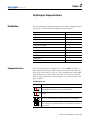
Library blocks let you work with fuzzy sets as defined by membership
functions. Let x be the linguistic variable and A(x) be the degree of
membership of x to the fuzzy set A defined by the sketched
membership function. FuzzyDesigner works with the following types
of membership functions.
8 / 2011
FuzzyDesigner Component Library
www.klinkmann.com
31
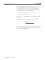
Trapezoidal Membership Function with Parameters (vertices): (a,b,c,d)
if x < a
0
⎧
⎪ ( x − a) /(b − a) if x ∈ [a, b)
⎪⎪
A( x) = ⎨
if x ∈ [b, c]
1
⎪( x − d ) /(c − d ) if x ∈ (c, d ]
⎪
if x > d
0
⎪⎩
A(x)
1
0
a
b
c
x
d
If a = b then A(a) = 1. If c = d then A(c) = 1.
Trapezoidal membership functions can be used in input and output
linguistic variable components.
S-shape Membership Function (cubic spline) with Parameters: (a,b,c,d)
A(x)
0
if x < a
⎧
⎪
⎪ 2 ( x − a) 2 ⎛⎜ x − 3b − a ⎞⎟ if x ∈ [a, b) 1
⎪ ( a − b)3
2 ⎠
⎝
⎪
A( x) = ⎨
1
if x ∈ [b, c]
⎪ 2
3c − d ⎞
⎛
⎪
( x − d )2 ⎜ x −
⎟ if x ∈ (c, d ]
2 ⎠
⎪ ( d − c )3
⎝
0
⎪
0
if x > d
⎩
a
b
c
x
d
If a = b then A(a) = 1. If c = d then A(c) = 1.
S-shape membership functions can be used in input and output
linguistic variable components.
Inverse Trapezoidal Membership Function with Parameters (vertices): (a,b,c,d)
1
if
x≤a
⎧
⎪( x − b) /(a − b) if x ∈ ( a, b]
⎪⎪
A( x) = ⎨
0
if x ∈ (b, c)
⎪( x − c) /(d − c) if x ∈ [c, d )
⎪
1
if
x≥d
⎪⎩
A(x)
1
0
a
b
c
d
x
If a = b then A(a) = 1. If c = d then A(c) = 1.
Inverse trapezoidal membership functions can be used in an input
linguistic variable component.
Publication LOGIX-UM004A-EN-P - March 2007
32
8 / 2011
FuzzyDesigner Component Library
www.klinkmann.com
Inverse S-shaped Membership Function (cubic spline) with Parameters: (a,b,c,d)
A(x)
1
if
x≤a
⎧
⎪
2
3
a
−
b
⎛
⎞
1
⎪
( x − b) 2 ⎜ x −
⎟ if x ∈ (a, b]
⎪ (b − a )3
2 ⎠
⎝
⎪
A( x) = ⎨
0
if x ∈ (b, c)
⎪ 2
3
d
c
−
⎛
⎞
⎪
( x − c) 2 ⎜ x −
⎟ if x ∈ [c, d )
2 ⎠
⎪ (c − d ) 3
⎝
0
⎪
1
if
x≥d
⎩
a
b
c
d
x
If a = b then A(a) = 1. If c = d then A(c) = 1.
Inverse S-shaped membership functions can be used in an input
linguistic variable component.
Singleton Membership Function with Parameter (position, center) c
⎧1 if x = c
A( x) = ⎨
⎩0 otherwise
A(x)
1
0
c
x
Singleton membership functions can be used in an output linguistic
variable component.
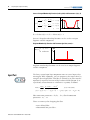
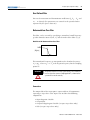
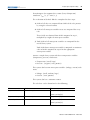
Input Port
The fuzzy system Input Port component stores an actual input value
entering the HFS. Optionally, you can preprocess the input values by
using the linear digital filter. This filter is defined by its pulse-transfer
operator H, expressed in terms of the backward-shift operator d, or
equivalently in time-domain as a difference equation, as follows.
H (d ) =
b ( d ) b0 + b1 d + L + bm d m
=
a(d )
1 + a1 d + L + a n d n
y ( t ) = − a1 y ( t − 1) − L − a n y ( t − n )
y ( d ) = H ( d )u ( d )
,
+
b0 u ( t ) + b1u ( t − 1) + L bm u ( t − m )
Filter numerator parameters : b0, b1, …bm ; filter denominator
parameters : a1, …an
There are two ways for designing the filter:
• user defined filter.
• butterworth low pass filter .
Publication LOGIX-UM004A-EN-P - March 2007
8 / 2011
FuzzyDesigner Component Library
www.klinkmann.com
33
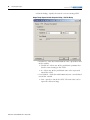
User Defined Filter
You set the numerator and denominator coefficients b0, b1, …bm and
a1, …an directly (the parameters are entered in the specified order
separated by the space character).
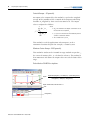
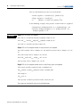
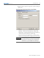
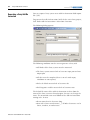
Butterworth Low Pass Filter
This filter can be created by specifying a normalized cutoff frequency
q, taken from the interval [0.01, 1], and the order of the filter (1,2,3).
Bode Plot of the Butterworth Low-Pass Filter
0dB
|H(jω)|
ωc
ω
This normalized frequency q corresponds to the absolute frequency
ωc = qωn , where ωn = π / Ts is the Nyquist frequency for the sampling
period Ts.
WARNING
All dynamical terms in a fuzzy system (filters, PID controllers)
have to share the common sampling period Ts; otherwise the
system will not work correctly.
Connections
The output link of the input port is connectable to all components
expecting a crisp value at the input. This includes the following
components:
•
•
•
•
Input Linguistic Variable
Output Port
Output Takagi-Sugeno Variable (accepts crisp values only)
PID (accepts crisp values only)
Publication LOGIX-UM004A-EN-P - March 2007
34
8 / 2011
FuzzyDesigner Component Library
www.klinkmann.com
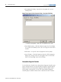
Parameters
• Name of the component
• Vector b = [b0, b1,,bm] , coefficients of the filter transfer function
numerator b(d)– optional
• vector a = [a1, …,an], coefficients of the filter transfer function
denominator a(d) – optional
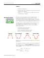
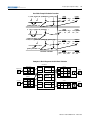
Input Linguistic Variable
The fuzzy system Input Linguistic Variable component stores
membership functions (fuzzy sets) of terms and is used for
fuzzification (classification) of the component input – a crisp value.
The component output is a vector of degrees of fulfillment of all terms
for the crisp input or degree of overlapping for the input fuzzy set.
An Input Linguistic Variable component consists of linguistic terms.
Each linguistic term is defined by a fuzzy set, that is by the
membership function and the name. There are four supported
membership functions.
•
•
•
•
trapezoid
Trapezoidal membership function
S-shaped membership function
Inverse trapezoidal membership function
Inverse S-shaped membership function
inverse trapezoid
s-shape
inverse s-shape
Linguistic terms are defined on specified range [xmin, xmax] (universe
of discourse).
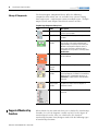
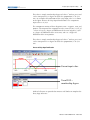
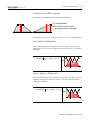
The component crisp input is fuzzified. The result of fuzzification of
the crisp input value x* is a degree of fulfillment (DOF) of the terms,
which is computed for each term given by the membership function
A(x) as follows.
⎧ A( x * ) if x * ∈ [ xmin , xmax ]
⎪
DOF ( A) = ⎨ A( xmin )
if x * < xmin
⎪ A( x )
if x * > xmax
max
⎩
Publication LOGIX-UM004A-EN-P - March 2007
8 / 2011
FuzzyDesigner Component Library
www.klinkmann.com
35
This value is simply membership degree of value x* to fuzzy set A and
can be interpreted as a degree to which the proposition (x* IS A) is
true. An example of fuzzification of the crisp input value x* is shown
in the figure Process of Crisp Input Fuzzification. The component
input value is -0.3191.
The component consists of three linguistic terms – negative, zero, and
positive. The output of the component is the vector [0.6383, 0.3617, 0]
– where 0.6383 is a degree of fulfillment of the term negative, 0.3617
is a degree of fulfillment of the term zero, and 0 is a degree of
fulfillment of the term positive.
This value is simply membership degree of value x* to fuzzy set A and
can be interpreted as a degree to which the proposition (x* IS A) is
true.
Process of Crisp Input Fuzzification
Current input value
Term DOF =
membership degree
DOFs of all terms are provided to connect rule blocks to complete the
fuzzy logic inference.
Publication LOGIX-UM004A-EN-P - March 2007
36
8 / 2011
FuzzyDesigner Component Library
www.klinkmann.com
Connections
The input link of the input linguistic variable is connectable to any of
these components providing a crisp value:
•
•
•
•
input Port component.
output Linguistic Variable component.
output Takagi-Sugeno Variable component.
PID component.
The output logical link of the input linguistic variable is connectable
to components expecting a DOF value (as a result of fuzzification or
defuzzification), such as the Rule Block component.
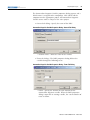
Parameters
• Name of the component
• Range of the input value of the component [xmin, xmax]
• List of terms described by
– Name
– Type of membership function
– Vector of membership function parameters [a, b, c, d]
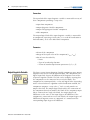
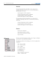
Output Linguistic Variable
Publication LOGIX-UM004A-EN-P - March 2007
The fuzzy system Output Linguistic Variable component stores output
linguistic terms and is used for defuzzification. The component has a
logical input link, degrees of fulfillment of all linguistic terms of the
respective linguistic variable. The link can be multiple, meaning that
the component can be connected to several rule blocks. The
component has two output links – value and logical links. Depending
on the selected inference algorithm and defuzzification method, the
component computes a crisp value y*. Such a result provides an
output value link. The output logical link enables the connection of
the component directly to another rule block. If the component input
link is connected to a single rule block, the output degrees of
fulfillment are the same as the input degrees of fulfillment. If the
component is connected to several rule blocks, the output degrees of
fulfillment of linguistic terms are computed as a maximum of the
corresponding input degrees of fulfillment.
8 / 2011
FuzzyDesigner Component Library
www.klinkmann.com
37
The Output Linguistic Variable component stores linguistic terms.
Each linguistic term is defined by its fuzzy set, that is, the membership
function and the name. The following membership functions are
supported:
• Trapezoidal membership function
• Singleton membership function
Linguistic terms are defined on the specified range [ymin, ymax]
(universe of discourse).
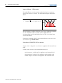
Defuzzification
Defuzzification converts fuzzy sets to a crisp value, taking into
account their degrees of fulfillment.
FuzzyDesigner supports the following defuzzification methods –
Centroid Average, Maximum Center Average, Mean of Maximum,
Smallest of Maximum, and Largest of Maximum.
y – output variable
Y – universe of output variable, defined by an
interval
A(y)
…
…
y* – crisp output value (after defuzzification)
Ai –membership function the output term i,
that is, its fuzzy set
cj
y*
cj+1
y
A – fuzzy set, which is being defuzzified,
obtained as a union of all “clipped” output
membership functions.
A(y) – membership degree of variable y in
fuzzy set A
Publication LOGIX-UM004A-EN-P - March 2007
38
8 / 2011
FuzzyDesigner Component Library
www.klinkmann.com
Centroid Average – CA generally
An output value computed by this method is equal to the weighted
average of the positions of the centroids of the output membership
functions Aj weighted by their actual activation levels. The output
value is computed as follows.
M
y =
*
∑ A(c j ) ⋅ c j
where:
• A(cj) is the maximum of the degrees of fulfillment over all
the rules with the consequent Aj
j =1
M
∑ A(c )
j =1
• cj is a position of the centroid of the membership function
Aj which is calculated in advance
j
• M is a number of fuzzy sets Aj
This method is used for applications when output is to be a
continuous function of inputs for example, a control system
Maximum Center Average – MCA generally
This method is similar to the Centroid Average method except that ci ,
the center of maxima of Bi , is calculated in advance. This method is
also continuous and allows the output value to reach the limits of the
range.
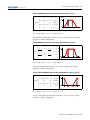
Defuzzification CA=MCA for singletons.
Output =
negative*DOF(negative) + zero*DOF(zero) + positive*DOF(positive)
DOF(negative) + DOF(zero) + DOF(positive)
Output = Default Value, if all term DOFs = 0
DOF(positive)
Publication LOGIX-UM004A-EN-P - March 2007
8 / 2011
FuzzyDesigner Component Library
www.klinkmann.com
39
Defuzzification CA and MCA for trapezoids.
Trapezoids are automatically transformed to singletons.
CA = centroid method
MCA = mean of maxima (to allow
reaching limit values of the range)
MCA CA
CA
MCA
The output value is then computed in the same way as for singletons.
Mean of Maxima – MOM generally
This method computes the mean value of the interval at which the
output fuzzy set reached the largest membership degree. It is defined
as follows.
{
}
y* = mean ci Ai (ci ) = max ( Aj (c j ) )
j
A(y)
…
…
y*
y
Smallest of Maxima – SOM generally
This method is similar to the previous one. Instead of mean value, the
minimum value of the interval is chosen. The defuzzified output is
computed as follows.
{
}
y* = smallest ci Ai (ci ) = max ( Aj (c j ) )
j
A(y)
…
…
y*
y
Publication LOGIX-UM004A-EN-P - March 2007
40
8 / 2011
FuzzyDesigner Component Library
www.klinkmann.com
Largest of Maxima – LOM generally
The only difference to the previous method is that the maximum
value of the interval is chosen. The defuzzified output is defined as
follows.
{
}
y* = largest ci Ai (ci ) = max ( Aj (c j ) )
j
A(y)
…
…
y*
y
Mean of Maxima, Smallest of Maxima, and Largest of Maxima methods
are not continuous and are mainly used in applications on
decision-making and classification when the task is to choose from
several alternatives.
If no term is activated (DOF = 0) then the inference result is set to a
user defined crisp default value.
Defuzzification SOM, MOM, LOM for singletons
Output value is computed as a reference singleton with maximal term
DOF.
If more terms have the same maximal DOF>0, then:
• SOM: output = smallest of the singletons with maximal DOF.
• LOM: output = largest of the singletons with maximal DOF.
• MOM: output = mean of the singletons with maximal DOF.
Publication LOGIX-UM004A-EN-P - March 2007
8 / 2011
FuzzyDesigner Component Library
www.klinkmann.com
41
Output = term with maximal DOF = zero
Output = Default Value, if all DOFs = 0
DOF(zero) is maximal
Defuzzification SOM, MOM, LOM for trapezoids
Trapezoids are automatically transformed to singletons.
SOM MOM LOM
The output value is then computed in the same way as for singletons.
Recommendation
• Use singletons to have easier insight to the output inference
mechanism
• No functionality is lost
Publication LOGIX-UM004A-EN-P - March 2007
42
8 / 2011
FuzzyDesigner Component Library
www.klinkmann.com
Connections
The input link of the output linguistic variable can be connected to a
component providing the DOF value (as a result of fuzzy inference),
that is, the Rule Block component.
The output value link of the output linguistic variable can be
connected to components expecting a crisp value, such as:
• Output Port component.
• Input Linguistic Variable component.
• Output Takagi-Sugeno Variable component (only crisp values
are considered).
• PID component (only crisp values are considered).
The output logical link of the output linguistic variable can be
connected to components expecting the DOF value (as a result of
fuzzification or defuzzification), that is, the Rule Block component.
Parameters
• Name of the component
• Range of the output value of the component [ymin, ymax]
• List of terms described by
– The name
– The type of membership function
– The vector of membership function parameters [a, b, c, d] for
the trapezoidal membership function, [c] for the singleton
membership function
• Type of fuzzy inference
• Type of defuzzification method
• Default output value
Output Takagi-Sugeno Variable
The classical model by Takagi-Sugeno offers a fuzzy rule based,
smooth switching between analytical functions. The consequent is a
crisp function of the antecedent variables rather than a fuzzy
proposition. A general form of a Takagi-Sugeno model is:
Ri: IF x is Ai THEN yi = fi(x)
Publication LOGIX-UM004A-EN-P - March 2007
8 / 2011
FuzzyDesigner Component Library
www.klinkmann.com
43
The consequent functions fi are typically chosen as instances of a
suitable parameterized function, whose structure remains equal in all
the rules and only the parameters vary. Most often, these functions are
linear combinations of antecedent variables. In control engineering,
each rule usually represents local dynamics in different state space
regions and the consequent is given in the form of a state-space or an
ARX model. The overall model of the system is achieved by fuzzy
blending of these linear models.
FuzzyDesigner supports Takagi-Sugeno fuzzy systems with linear
functions in the rule consequents written in the following form.
Ri : IF x1 is Ai1 and Land xn is Ain THEN y = ai 0 + ai1 x1 + K + ain xn
or
Ri : IF x1 is Ai1 and Land xn is Ain THEN y = ai 0
The Takagi-Sugeno fuzzy system with the constant value in the rule
consequents can be also considered as a fuzzy system with singleton
membership functions in the rule consequents. If the Centroid
Average or Maximum Centroid Average defuzzification and Fuzzy
Arithmetic Inference method is chosen, than the behavior of both
fuzzy systems is the same.
The fuzzy system Output Takagi-Sugeno Variable component stores
parameters of reference linear or constant consequent functions. The
component has two input links – a logical input link (degrees of
fulfillment of all reference functions) that can be multiple, meaning
that the component can be connected to several rule blocks, and a
value input link (connectable to components that produce crisp
values), which can be multiple too. The number of links depends on
the number of consequent variables.
The component has two output links:
• Value link
• Logical link
The output logical link enables the connection of the component
directly to other rule blocks. If the component input link is connected
to one rule block, the output degrees of fulfillment are the same as the
input degrees of fulfillment. If the component is connected to several
rule blocks, the output degrees of fulfillment of reference membership
functions are computed as a maximum of the corresponding input
degrees of fulfillment.
Publication LOGIX-UM004A-EN-P - March 2007
44
8 / 2011
FuzzyDesigner Component Library
www.klinkmann.com
The output Takagi-Sugeno Variable component consists of functional
terms. Each functional term is defined by its parameters (a0, a1, … an)
and its name (the parameters are entered in the specified order
separated by the space character). The type of every linguistic term
can be different. There are two supported functions.
• Linear function: f(x1,x2,...xn) = a0 + a1 x1 + a2 x2 +...+ an xn
• Constant function: f(x1,x2,...xn) = a0
Where x1,x2,...xn are outputs from preceding components providing
crisp values.
The component calculates an inference result as a crisp value y*
y =
*
∑ dof
i
i
⋅ f i ( x1 , x2 ,L, xn )
∑ dof
i
i
where dofi is DOF of i-th term. This value is finally limited to the range
[ymin, ymax]. If no term is activated (DOF = 0) the inference result is a
user-defined crisp default value.
Publication LOGIX-UM004A-EN-P - March 2007
8 / 2011
FuzzyDesigner Component Library
www.klinkmann.com
EXAMPLE
45
Different linear-state feedback controllers are to be smoothly activated for different process states and
setpoints – scheduling controller gains. There are three rules.
• IF (x1 IS A1 ) AND (x2 IS B1) THEN y = K0 + K1*x1 + K2*x2 (= y1)
• IF (x1 IS A2 ) AND (x2 IS B2) THEN y = G0 + G1*x1 + G2*x2 (= y2)
• IF (x1 IS A3 ) AND (x2 IS B3) THEN y = C0 (= y3)
Defined (functional) terms:
K, type LINEAR, parameters = K0 K1 K2
G, type LINEAR, parameters = G0 G1 G2
C, type CONSTANT, parameters = C0
Evaluation (weighted average of functions):
x1
x2
from a rule block
y
to a rule block
y=
y1*DOF(K) + y2*DOF(G) + y3*DOF(C)
DOF(K) + DOF(G) + DOF(C)
y = Default Value, if all DOFs = 0
Connections
The input logical link of the output Takagi-Sugeno variable can be
connected to a component providing a DOF value (as result of fuzzy
inference), that is, the Rule Block component.
Publication LOGIX-UM004A-EN-P - March 2007
46
8 / 2011
FuzzyDesigner Component Library
www.klinkmann.com
The input value link of the output Takagi-Sugeno variable can be
connected to components providing a crisp value, such as:
•
•
•
•
Input Port component.
Output Linguistic Variable component.
PID component.
Output Takagi-Sugeno Variable component.
The output value link of the output Takagi-Sugeno variable can be
connected to components expecting a crisp value, such as:
• Output Port component.
• Input Linguistic Variable component.
• Output Takagi-Sugeno Variable component (only crisp values
are considered).
• PID component (only crisp values are considered).
The output logical link of the output Takagi-Sugeno variable can be
connected to components expecting a DOF value (as result of
fuzzification or defuzzification), such as the Rule Block component.
Parameters
• Name of the component
• Range of the input value of the component [ymin, ymax]
• List of functional terms described by
– The name
– The type of the function
– The vector of the function parameters [a0, a1, … , an] for the
linear function, [a0] for the constant function
• Default value
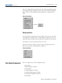
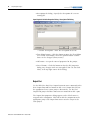
Intermediate Linguistic
Variable
The fuzzy system Intermediate Linguistic Variable component is used
as a buffer allowing logical chaining of rule blocks.
The component consists of linguistic terms with symbolic meaning.
Each linguistic term is defined by its name. Degrees of fulfillment of
all terms are results of previous logic inference in preceding rule
blocks connected to this component.
Publication LOGIX-UM004A-EN-P - March 2007
8 / 2011
FuzzyDesigner Component Library
www.klinkmann.com
47
If the component input link is connected to a single rule block, the
output degrees of fulfillment just copy inputs. If the component input
is connected to several rule blocks, the output degrees of fulfillment
of stored linguistic terms are computed as a maximum of the
corresponding input degrees of fulfillment.
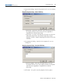
Connections
The input logical link of the Intermediate Linguistic Variable can be
connected to a component providing a DOF value (as result of fuzzy
inference in a rule block), that is, the Rule Block component.
The output logical link of the Intermediate Linguistic Variable can be
connected to components expecting a DOF value (as result of
fuzzification or fuzzy inference in a rule block), such as the Rule
Block component.
Parameters
• Name of the component
• List of terms defined by their names
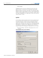
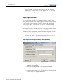
Rule Block
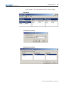
The fuzzy system Rule Block component stores rules, performs fuzzy
logic inference based on fuzzy rules and computes degrees of
fulfillment of linguistic terms for consequent variables (output logical
links) from degrees of fulfillment of linguistic terms used in the rule
for premise variables (input logical links).
Publication LOGIX-UM004A-EN-P - March 2007
48
8 / 2011
FuzzyDesigner Component Library
www.klinkmann.com
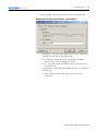
Supported Format of Rules
Multiple notations are used in the explanation of the supported format
of rules.
• X1, X2,…, Xn – premise variables
• Y1, Y2,…, Ym. – consequent variables
• Ai1, Ai2,… – terms defined for the premise variable Xi
• Bj1, Bj2,… – terms defined for the consequent variable Yj
EXAMPLE
IF (X1 IS A13) AND (X2 IS A21) AND … AND (Xn IS An1) THEN
(Y1 IS B12) [w1] , (Y2 IS B21) [w2], … (Yn IS Bn3) [wn]
where wk ∈ [0,1] is rule weight of the k-th consequent.
Schematically the rule can be rewritten as follows:
(A13 , A21 , … , An1) Æ (B12 [w1] , B21 [w2] , … , Bn3 [wn] )
This rule base format is very useful in manual design. It can be
represented in the form of a table where every column
corresponds to one variable and rows of the table are filled
with appropriate terms or optionally with their inversions
(applying the NOT operator).
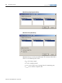
FuzzyDesigner also supports the OR operator.
EXAMPLE
IF [(X1 IS A11) OR (X1 IS A12) OR ... ] AND (X2 IS A21) AND …
AND (Xn IS An1) THEN (Y1 IS B12)
You define the number of terms in the OR expression.
The NOT operator can be applied to the whole OR expression.
IF [ NOT [(X1 IS A11) OR (X1 IS A12) OR ... ]] AND (X2 IS A21)
AND … AND (Xn IS An1) THEN (Y1 IS B12) [w1] , (Y2 IS B21)
[w2], …
The rule block component performs fuzzy logic inference based on
fuzzy rules. In a simplified way, it computes degrees of fulfillment of
consequent variables from degrees of fulfillment of premise variables
by using fuzzy t-norms and s-norms (t-conorms).
FuzzyDesigner supports the following t-norms (fuzzy AND operators):
• Minimum: Tmin (x, y) = min (x, y)
• Product: Tprod (x, y) = x · y
Publication LOGIX-UM004A-EN-P - March 2007
8 / 2011
FuzzyDesigner Component Library
www.klinkmann.com
49
FuzzyDesigner also supports this s-norm (fuzzy OR operator):
maximum: Smax (x, y) = max (x, y)
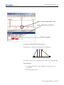
The evaluation of the Rule Block is completed in three steps.
1. DOFs of all rules are computed from DOFs of the rule premise
by using the selected t-norm.
2. DOFs of all conseqent variables terms are computed for every
rule.
These DOFs are obtained from DOFs computed in step 1,
multiplied by weights of consequent variables.
3. Total DOFs of all consequent variables are computed for the
overall fuzzy system.
Total DOF of one consequent variable is computed as maximum
value of DOFs computed in step 2 for the appropriate
consequent variable.
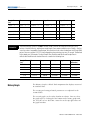
Assume a simple fuzzy system with these two premise variables
(temperature, pressure) with terms:
• Temperature: (small, large)
• Pressure : (negative, zero, positive)
This system also has two consequent variables: (voltage, current) with
terms:
• Voltage: (small, medium, large)
• Current : (zero, positive)
This system also has a minimum t-norm.
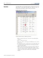
The rule base can be formulated as the following.
If
And
Then
Temperature is small
Oressure is negative
Voltage is medium [0.9]
Current is positive [1.0]
Temperature is large
Pressure is positive
Pressure is negative
Voltage is small [0.8]
Voltage is small [1.0]
Current is positive [1.0]
Publication LOGIX-UM004A-EN-P - March 2007
50
8 / 2011
FuzzyDesigner Component Library
www.klinkmann.com
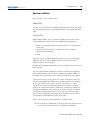
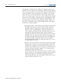
You can also formulate the rule base schematically:
• (small, negative) → (medium [0.9] , positive [1.0]).
• (large, negative) → (small [0.8] ,
).
•(
, positive) → (small [1.0] , positive [1.0]).
In the following example, some premise variable DOFs are supposed.
• Temperature: DOFtemp(small) = 0.4 , DOFtemp(large) = 0.8
• Pressure: DOFpress(negative) = 0.1 , DOFpress(zero) = 0.9 ,
DOFpress(positive) = 0.5
EXAMPLE
Step 1: DOFs of all rules are computed.
Rule 1: DOFrule1 = min (DOFtemp(small), DOFpress(negative)) = min(0.4, 0.1) = 0.1
Rule 2: DOF rule2 = min (DOFtemp(large), DOFpress(negative)) = min(0.8, 0.1) = 0.1
Rule 3: DOF rule3 = min (DOFpress(positive)) = min(0.5) = 0.5
Step 2: DOFs of all consequent variables for every rule terms are computed.
Rule 1: DOFvolt (medium) = DOFrule1 · Weightvolt = 0.1 · 0.9 = 0.9, DOFcurr (positive) = DOFrule1 · Weightcurr = 0.1 · 1.0 =
0.1
Rule 2: DOFvolt (small) = DOFrule2 · Weightvolt = 0.1 · 0.8 = 0.8
Rule 3: DOFvolt (small) = DOFrule1 · Weightvolt = 0.5 · 1.0 = 0.5
DOFcurr (positive) = DOFrule1 · Weightcurr = 0.5 · 1.0 = 0.5
Step 3: DOFs of all consequent variables terms for overall fuzzy system are computed.
DOFvolt (small) = max (DOFvolt (small) for all rules) = max (0.08, 0.5) = 0.5
DOFvolt (medium) = max (DOFvolt (medium) for all rules) = max (0.09) = 0.09
DOFvolt (large) = 0
DOFcurr (zero) = 0
DOFcurr (positive) = max (DOFcurr (positive) for all rules) = max (0.1, 0.5) = 0.5
These steps are schematically shown on the following figures.
Publication LOGIX-UM004A-EN-P - March 2007
8 / 2011
FuzzyDesigner Component Library
www.klinkmann.com
51
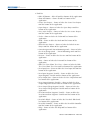
Set of Rules Example Evaluation Procedure
1. (small, negative) Æ (medium [0.9] , positive [1.0])
0.4
0.1
* 0.09
min
premise part: DOF = 0.1
current
zero , positive
0.0 , 0.1
voltage
small , medium , large
0.08 , 0.0 , 0.0
current
zero , positive
0.0 , 0.0
voltage
small , medium , large
0.5 , 0.0 , 0.0
current
zero , positive
0.0 , 0.5
voltage
small , medium , large
0.5 , 0.09 , 0.0
current
zero , positive
0.0 , 0.5
* 0.1
2. (large, negative) Æ (small [0.8] ,
0.8
voltage
small , medium , large
0.0 , 0.09 , 0.0
0.1
)
* 0.08
min
premise part: DOF = 0.1
3. (
, positive) Æ (small [1.0] , positive [1.0])
0.5
* 0.5
min
premise part: DOF = 0.5
* 0.5
total DOF = maximum
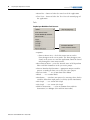
Example of a Block Diagram of the Rule Block Evaluation
Rule Block
temperature
temperature
voltage
small
small
0.4
large
negative
Æ
0.09
positive [1.0]
0.1
0.8
large
pressure
pressure
medium [0.9]
negative
negative
0.1
zero
0.2
positive
0.5
small [0.8]
Æ
0.08
max 0.5
small
max 0.09 medium
max 0.0
voltage
Æ
large
0.0
current
positive
Æ
small [1.0]
0.5
max 0.0
zero
positive [1.0]
0.5
max 0.5
positive
current
Æ
Publication LOGIX-UM004A-EN-P - March 2007
52
8 / 2011
FuzzyDesigner Component Library
www.klinkmann.com
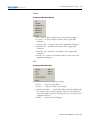
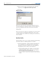
Connections
The input logical link of the Rule Block can be connected to a
component providing a DOF value (as a result of fuzzification or
defuzzification), such as the:
•
•
•
•
Input Linguistic Variable component.
Output Takagi-Sugeno Variable component.
Output Linguistic Variable component.
Intermediate Linguistic Variable component.
The output logical link of the Rule Block can be connected to
components expecting a DOF value (as result of fuzzy inference),
such as the:
• Output Takagi-Sugeno Variable component.
• Output Linguistic Variable component.
• Intermediate Linguistic Variable component.
Parameters
•
•
•
•
PID Controller
Name of the component
List of links to premise variables
List of links to consequent variables
Type of t-norm
The fuzzy system PID component enables you to design an intelligent
supervision of a conventional PID controller.
The following symbols and terminology are used in description of the
component:
•
•
•
•
•
•
•
•
•
Publication LOGIX-UM004A-EN-P - March 2007
PV – process variable
CV – control variable
SP – set point
E – error, E = SP-PV
P- proportional gain,
I- integral gain,
D- derivative gain
Man – manually set value of CV
Mode – controller mode
8 / 2011
FuzzyDesigner Component Library
www.klinkmann.com
53
The component can be used as a conventional PID controller with
supervised parameters defined by component input links. The
component output link provides a crisp value representing the control
variable.
The component functionality is defined through the equation format
with the option of using either independent gains or dependent gains.
When the independent gains option is used, the proportional, integral
and derivative gains affect only their specific proportional, integral or
derivative terms respectively. When the dependent gains option is
used, the proportional gain is replaced with a controller gain, which
affects all three parts. Both formats are shown in the following
equations.
t
⎛
dO (t ) ⎞
⎟ + Bias
CV = P⎜⎜ (b ⋅ SP (t ) − PV (t ) ) + ∫ I ⋅ E (t ) dt + D
⎟
dt
0
⎝
⎠
t
CV = P (b ⋅ SP (t ) − PV (t ) ) + ∫ I ⋅ E (t ) dt + D
0
dO (t )
+ Bias
dt
Where parameter b can be defined by the user and has to be in
interval [0,1]. The default value is 1. This parameter dampens the
influence of the setpoint on the proportional action.
The component allows two formats of derivative term O(t). Derivative
input to the controller can be either the process variable PV(t) or the
error E(t). Use of the process variable eliminates output spikes
resulting from setpoint changes. Use of the error allows fast responses
to setpoint changes when the algorithm can tolerate overshoots.
The algorithm is implemented in the discrete form.
Numerical integration is implemented as follows:
∫ I ⋅ Edt :
Itermk = IEk Ts + Itermk −1
where Ts is the loop update time.
Numerical derivation is implemented as follows:
dO
:
dt
ΔOk =
Ok − Ok −1
Ts
The calculation of the derivative term is enhanced by using a
smoothing first order low pass digital filter. This filter eliminates large
derivative term spikes caused by noise in the process variable.
Publication LOGIX-UM004A-EN-P - March 2007
54
8 / 2011
FuzzyDesigner Component Library
www.klinkmann.com
ΔOk = (1 − α )
Ok − Ok −1
+ αΔOk −1
Ts
α=
where
1
T
16 s + 1
D
.
Finally the control variable CV is computed in the following way:
CVk = P ⋅ ( Ek + Itermk + D ⋅ ΔOk ) + Bias
CVk = P ⋅ Ek + Itermk + D ⋅ ΔOk + Bias
in the case of dependent gains and independent gains respectively.
The controller can be used in two different modes – Manual mode
and Automatic mode (default mode). During Manual mode the
parameter Mode, which is defined by the input link, has to be set to 1.
In this mode the controller calculates the user defined control
variable, which is connected to the input link Man. During this mode
the controller calculates the internal state of the integrator from the
user defined control variable to achieve a bumpless transfer when the
operator changes the control mode from manual to automatic. In the
Automatic mode, when the parameter Mode is set to 0, the controller
provides the computed value of the control variable. If input links
Man and Mode are not fed, the default (automatic) mode is applied.
The component also provides the user additional features – output
limiting with anti-reset windup, dead band control and gain forgetting
factor.
Output limiting allows applies limits CV_min and CV_max to the
control variable. If the output limiting is enabled, and the computed
control variable exceeds the limits, the CV is saturated. When the
value of the computed control variable reaches or exceeds limits, the
integration is paused until the value of the computed control variable
comes back into the range.
The adjustable dead band DB lets the user select an error interval DBI
= [SP-DB, SP+DB] around the setpoint where the controller output
does not change as long as the error remains within this range. This
dead band lets you control how closely the process variable matches
the setpoint without changing the value of CV. There are two choices
of dead band type – zero crossing and no zero crossing dead band.
Publication LOGIX-UM004A-EN-P - March 2007
8 / 2011
FuzzyDesigner Component Library
www.klinkmann.com
55
Zero crossing dead band control stops changing control variable (ΔCV
= 0) when the process variable crosses the setpoint. The control
variable is not changed as long as the process variable remains within
the dead band interval. Zero crossing dead band control can be
written as follows:
Once PV reaches SP (E = 0) and as long as PV∈ DBI , use ΔCV = 0
(consider E = 0)
No zero crossing dead band control stops changing control variable
immediately when approaching the setpoint and crossing the band
limits. The control variable is not changed as long as the process
variable remains in the dead band interval. No zero crossing dead
band control can be written as follows:
IF (PV∈ DB) THEN ΔCV = 0 (consider E = 0)
When the gain parameters of the PID controller are supervised by
fuzzy rules, rapid changes of premise rules variables may cause rapid
changes of controller gains. To avoid these changes the gain forgetting
factor g can be used. The value of g has to be in the interval [0.001 1].
Value g = 1 corresponds to exact parameter tracking (no forgetting
factor is applied) and g = 0.001 corresponds to very slow parameter
tracking. The default value is 1.
Connections
The Input links of the PID component can be connected to all
components providing crisp values, such as:
•
•
•
•
Input Port component.
Output Takagi-Sugeno Variable component.
Output Linguistic Variable component.
PID component (theoretically).
The output link of the PID component can be connected to all
components expecting a crisp value, such as:
•
•
•
•
Output Port component.
Input Linguistic Variable component.
Output Takagi-Sugeno Variable component (theoretically).
PID component (theoretically).
Publication LOGIX-UM004A-EN-P - March 2007
56
8 / 2011
FuzzyDesigner Component Library
www.klinkmann.com
Parameters
• Name of the component
• Controller Gain parameters (P, I, D), Bias – specified by links to
components providing crisp values or by user defined constant
values
• Setpoint value SP – specified by links to components providing
crisp values or by user defined constant values
• Sampling period Ts
• Output limiting of control variable – YES or NO
• Output limits – [CVmin, CVmax] (if YES)
• Equation format – dependent or independent gains
• Derivative input format – error or process variable
• Manual control (None or the link to component which defines
the manual control variable)
• Mode – 0 (automatic) or 1 (manual)
• Parameter b - dampens the influence of the setpoint on the
proportional action
• Dead band – YES or NO
• Dead Band Radius (if YES)
• Dead Band Type – Zero Crossing or No Zero Crossing (if YES)
• Gain forgetting factor
Output Port
The Output Port component stores an actual output value of the HFS
provided by a preceding component. The output is a crisp value.
Connections
The input link of the output port can be connected to all components
providing a crisp value, such as:
•
•
•
•
Input Port component.
Output Takagi-Sugeno Variable component.
Output Linguistic Variable component.
PID component.
Parameters
• Name of the component
Publication LOGIX-UM004A-EN-P - March 2007
Chapter
8 / 2011
www.klinkmann.com
3
FuzzyDesigner Graphical User Interface
Introduction
The FuzzyDesigner graphical user interface (GUI) is illustrated by a
simple academic Ball and Beam experiment provided as one of the
sample projects when you install FuzzyDesigner.
Topic
Page
Setting Options
57
FuzzyDesigner Control Basics
59
The objective is to stabilize the ball at the desired position on the
beam. The main screen of the FuzzyDesigner GUI with the opened
project named ball (this is our Ball and Beam example), can be seen
below.
Ball and Beam Project in FuzzyDesigner
Setting Options
57
There are some FuzzyDesigner features that can be configured
according to personal preferences and for particular projects. You can
access the customization options from the View and Options menu
commands.
Publication LOGIX-UM004A-EN-P - March 2007
58
8 / 2011
FuzzyDesigner Graphical User Interface
www.klinkmann.com
Tool Bar
The Tool Bar (see FuzzyDesigner Tool Bar) submenu on the View
menu enables access to the commands for customizing the
FuzzyDesigner tool bar. A tool bar button can be set as visible or
invisible by clicking the appropriate Tool Bar submenu commands.
FuzzyDesigner Tool Bar
Status Bar
The Status Bar (see FuzzyDesigner Status Bar) menu command on
the View menu enables you to set the status bar of FuzzyDesigner as
visible or as invisible. The status bar shows FuzzyDesigner modes (see
FuzzyDesigner Control Basics), and error messages.
FuzzyDesigner Status Bar
Tree View
The Tree View (see FuzzyDesigner Tree View) menu command on
the View menu enables you to set the Tree View tab control page
visible or invisible (see Working with Projects). You can also do this
by clicking the tool bar button with the same name (shown as a tool
tip).
To resize the Tree View tab control page, use your mouse and drag
the splitter on the right side of the tab control.
Publication LOGIX-UM004A-EN-P - March 2007
8 / 2011
FuzzyDesigner Graphical User Interface
www.klinkmann.com
59
FuzzyDesigner Tree View
FuzzyDesigner Control Basics
The controls in FuzzyDesigner are very similar to other Microsoft
Windows applications, and are easy to use.
FuzzyDesigner’s functions can be accessed from the main menu or by
clicking the tool bar button commands. By right-clicking the tree view
item or in the FuzzyDesigner project window, a related pop-up menu
appears. You can also control most of the functions using these
pop-up menus. These menus are context-sensitive; they offer the most
useful commands applicable to the current window.
Use the Project\Recent Projects menu command to reopen the most
recent projects in FuzzyDesigner. Up to four projects are shown in the
Recent Projects menu.
Detailed Help is accessible through the FuzzyDesigner main menu.
The Help button can be used in the Term and the Rule Editor tool
bars as well. Using this button, information about the particular editor
can be displayed.
You can apply the Edit\Undo and Edit\Redo menu commands to a
few changes made in the active project. The Undo menu command is
always applied to the last change in the active project and the Redo
menu command is always applied to the next change in the history of
changes made in the active project.
Publication LOGIX-UM004A-EN-P - March 2007
60
8 / 2011
FuzzyDesigner Graphical User Interface
www.klinkmann.com
FuzzyDesigner has two main modes, Design mode and Monitoring
mode. FuzzyDesigner defaults to the Design mode, where you can
design the project, set or reset options and use all application tools
without any restriction. Use the Monitoring mode when you need to
change the project parameters only, and leave the project design
unchanged. Options and tools that can enable project design changes
are restricted in the Monitoring mode. The current mode is indicated
in the application Status Bar.
IMPORTANT
The Monitoring mode can be switched on or off directly from
the Edit|Go to Design mode …/Go to Monitoring mode main
menu item or the tool bar with the same name in the tool tip.
The Monitoring mode is automatically enabled when the
following dialoges are opened:
• Watch
• Simulation Watch
• Project Installation Wizard
• Online Connection Wizard Panel
• Monitoring Stand-Alone Component
After you close all of the open dialoges, FuzzyDesigner
switches to the Design mode.
You can minimize, maximize or restore all windows opened in the
FuzzyDesigner work area from the menu commands in the Window
menu.
Main Menu
This section lists all menu items in the main menu bar of the
FuzzyDesigner main window.
FuzzyDesigner Main Menu
Publication LOGIX-UM004A-EN-P - March 2007
8 / 2011
FuzzyDesigner Graphical User Interface
www.klinkmann.com
61
Project
FuzzyDesigner Main Menu Project Structure
•
•
•
•
•
•
•
•
•
•
•
New – creates a new project
Open … – opens an existing project
Close – closes the active project
Close All – closes all open projects
Save – saves the active project
Save As … – save the active project with a different name
Project Information … – displays the properties for the current
project
Preview – shows the preview of the currently active project
Print … – prints the active project
Recent Projects – shows the four most recent projects
Exit – closes the FuzzyDesigner application
Edit
FuzzyDesigner Main Menu Edit Structure
• Undo – see section FuzzyDesigner Control Basics
• Redo – see section FuzzyDesigner Control Basics
• Refresh – updates the display of the active project
Publication LOGIX-UM004A-EN-P - March 2007
62
8 / 2011
FuzzyDesigner Graphical User Interface
www.klinkmann.com
• Go to Design mode …/Go to Monitoring mode – switches the
project between the Design mode and Monitoring mode (see
section FuzzyDesigner Control Basics)
• New Port
– New Input Port … – see section Input Port
– New Output Port … – see section Output Port
• New Variable
– New Input Linguistic Variable … – see section Input
Linguistic Variable
– New Output Linguistic Variable … – see section Output
Linguistic Variable
– New Output Takagi-Sugeno Variable … – see section Output
Takagi-Sugeno Variable
– New Intermediate Linguistic Variable … – see section
Intermediate Linguistic Variable
• New Rule Block … – see section Rule Block
• New PID Controller … – see section PID Controller
View
FuzzyDesigner Main Menu View Structure
Publication LOGIX-UM004A-EN-P - March 2007
8 / 2011
www.klinkmann.com
FuzzyDesigner Graphical User Interface
63
• Tool Bar
– Hide All Buttons – hides all tool bar buttons of the application
– Show All Buttons – shows all tool bar buttons of the
application
– Create New Project – shows or hides the Create New Project
tool bar button of the application
– Open Project – shows or hides the Open Project tool bar
button of the application
– Save Active Project – shows or hides the Save Active Project
tool bar button of the application
– Undo – shows or hides the Undo tool bar button of the
application
– Redo – shows or hides the Redo tool bar button of the
application
– Refresh Active Project – shows or hides the Refresh Active
Project tool bar button of the application
– Go to Design mode/Go to Monitoring mode – shows or hides
the Go to Design mode …/Go to Monitoring mode tool bar
button of the application
– Preview – shows or hides the Preview tool bar button of the
application
– Print – shows or hides the Print tool bar button of the
application
– Hide Tree View/Show Tree View – shows or hides the Hide
Tree View/Show Tree View tool bar button of the application
– New Input Port – shows or hides the New Input Port tool bar
button of the application
– New Input Linguistic Variable – shows or hides the New
Input Linguistic Variable tool bar button of the application
– New Output Port – shows or hides the New Output Port tool
bar button of the application
– New Output Linguistic Variable – shows or hides the New
Output Linguistic Variable tool bar button of the application
– New Output Takagi-Sugeno Variable – shows or hides the
New Output Takagi-Sugeno Variable tool bar button of the
application
– New Intermediate Linguistic Variable – shows or hides the
New Intermediate Linguistic Variable tool bar button of the
application
– New Rule Block – shows or hides the New Rule Block tool
bar button of the application
– New PID Controller – shows or hides the New PID Controller
tool bar button of the application
– Help – shows or hides the Help tool bar button of the
application
Publication LOGIX-UM004A-EN-P - March 2007
64
8 / 2011
FuzzyDesigner Graphical User Interface
www.klinkmann.com
• Status Bar – shows or hides the status bar of the application
• Tree View – shows or hides the Tree View tab control page of
the application
Tools
FuzzyDesigner Main Menu Tools Structure
• Options
– Show in Status Area – check this menu item to set the
FuzzyDesigner to the server mode. The FuzzyDesigner icon
shows in the status area and the application should be closed
only through the icon context menu.
• Reset Internal States – resets the internal states of all Input Port
filters and PID Controllers in the just active project
• Process Membership Functions – appropriate output variables
process according to fuzzy sets in the just active project
• Set Port Order … – see section Port Order Editor
• Watch … – see section Watch
• Simulation … – simulate your process by entering values for the
variables defined on input ports (see Fuzzy System Simulation)
• 2D Graph … – see section 2D Graph
• 3D Graph … – see section 3D Graph
• Add-On Instruction … – create or monitor fuzzy Add-On
Instructions (see RSLogix 5000 Add-On Instruction)
Publication LOGIX-UM004A-EN-P - March 2007
8 / 2011
FuzzyDesigner Graphical User Interface
www.klinkmann.com
65
Window
FuzzyDesigner Main Menu Window
• Tile – tiles all open windows in the application workplace
• Cascade – cascades all open windows in the application
workplace
• Arrange Icons – arranges icons in the application workplace
• Minimize All – minimizes all windows in the application
workplace
• Maximize All – maximizes all windows in the application
workplace
• Restore All – restores all windows to their normal size in the
application workplace
Help
FuzzyDesigner Main Menu Help
•
•
•
•
Contents … – shows the help contents
Index … – shows the help index
Search … – shows the help search dialog
Product Activation … – shows the Product Activation dialog with
the Computer ID. Send this together with the serial number to
technical support to get the Activation Key to access the desired
application features.
• About … – about the FuzzyDesigner
Publication LOGIX-UM004A-EN-P - March 2007
66
8 / 2011
FuzzyDesigner Graphical User Interface
Tool Bar Menu
www.klinkmann.com
This section lists all menu buttons in the tool bar menu (see
FuzzyDesigner Tool Bar) of the FuzzyDesigner main window.
•
•
•
•
•
•
•
•
•
•
•
•
•
•
•
•
•
•
•
Publication LOGIX-UM004A-EN-P - March 2007
Create new project
Open project
Save active project
Undo – see section FuzzyDesigner Control Basics
Redo – see section FuzzyDesigner Control Basics
Refresh – evaluates static the just active project
Go to Design Mode…/Go to Monitoring Mode – switches
FuzzyDesigner between the Design and Monitoring Mode (see
section FuzzyDesigner Control Basics)
Preview – shows the preview of the current project
Print
Hide Tree View – see section FuzzyDesigner Tree View
New Input Port
New Input Linguistic Variable
New Output Port
New Output Linguistic Variable
New Output Takagi-Sugeno Variable
New Intermediate Linguistic Variable
New Rule Block
New PID Controller
Help – shows the FuzzyDesigner help
Chapter
8 / 2011
www.klinkmann.com
4
FuzzyDesigner Projects
Introduction
The basic working unit in the FuzzyDesigner is a project. This chapter
describes the concept of a project.
Topic
Page
Working with Projects
67
Designing a Fuzzy System
72
Fuzzy System Components
75
Term Editor
102
Term Properties Dialog
105
Rule Editor
108
Port Order Editor
113
Watch
113
History Graph
117
2D Graph
122
3D Graph
125
A project is a set of data containing information related to a particular
fuzzy system. Designing a fuzzy system involves several steps –
definition of components and links between components, design of
membership functions, and creating fuzzy rules.
Working with Projects
Most of the commands used for basic operations with projects can be
found in the Project menu. This menu contains the following
commands:
•
•
•
•
•
•
•
New – creates a new project
Open – opens an existing project
Close – closes the currently active project
Close All – closes all opened projects
Save – saves the currently active project
Save As – saves the currently active project to new file
Project Information – shows the information about the currently
active project
• Preview – shows the preview of the currently active project
window
67
Publication LOGIX-UM004A-EN-P - March 2007
68
8 / 2011
FuzzyDesigner Projects
www.klinkmann.com
• Print – prints the project window of the currently active project
• Recent Projects – shows the four most recent projects
• Exit – closes FuzzyDesigner
All opened projects and their components are seen in the Tree View
tab control page. When you right-click a tree view node, a context
sensitive menu appears. When you right-click the Projects node, a
context menu with the following commands appears (see Projects
Tree View Node Context Menu):
• New – creates a new project (see section Creating a Project)
• Open – opens an existing project (see section Opening an
Existing Project)
• Close All – closes all opened projects (see section Closing a
Project)
Projects Tree View Node Context Menu
When you right-click the opened project node, a context menu with
the following commands appears (see Project Tree View Node
Context Menu):
• Close – closes the project (see section Closing a Project)
• Save – saves the project (see section Saving a Project)
• Save As – saves the currently active project to new file (see
section Saving a Project)
• Preview – shows the project preview
• Print – prints the project (see section Printing a Project)
Project Tree View Node Context Menu
There are project component type nodes of the applied components
under the node of each opened project. When you right-click the
component type node, a context menu with the following command
appears (see Component Type Tree View Node Context Menu):
Publication LOGIX-UM004A-EN-P - March 2007
8 / 2011
FuzzyDesigner Projects
www.klinkmann.com
69
• Delete All – deletes all applied components with the appropriate
type from the project.
Component Type Tree View Node Context Menu
There are component nodes of the applied components under the
appropriate component type node of each opened project. When you
right-click the component node, a context menu with the following
commands appears (see Component Tree View Node Context Menu):
• Delete – deletes the selected component from the project
• Properties – shows the properties dialog of the selected
component (see section Fuzzy System Components)
Component Tree View Node Context Menu
Creating a Project
Create a new project by using the Project\New main menu command
or the New context menu command of the Projects tree view node.
When a new project is created, the appropriate tree view node and
project window will be added. A new project is not automatically
saved. To save a recently created project, use the Save As command
(see section Saving a Project) in the Project menu.
Opening an Existing Project
Follow these steps to open the existing project.
1. Select the Project\Open main menu command or the Open
context menu command of the Projects tree view node.
2. From the Open dialog, choose the appropriate file type (fsp)
and click or type the name of the project file.
Publication LOGIX-UM004A-EN-P - March 2007
70
8 / 2011
FuzzyDesigner Projects
www.klinkmann.com
3. When you select a fsp-file type, a file in the XML format with all
project information will open.
When the selected file has no information about the project
graphical representation or about FuzzyDesigner GUI, the
project will be opened with a default graphical representation
and FuzzyDesigner GUI information (without the project
description, for example).
4. Click Open.
When the project opens successfully, the appropriate tree view
node will be added to the Tree View tab control page and the
project window will be opened in the application workplace
with appropriate recently opened dialogs.
FuzzyDesigner is a Multi-Document Interface (MDI) application, so
you can open more then one project at a time. Only one of the
currently opened projects can be active, so all the tool bar button
commands associated with a project are applied to this active project.
The FuzzyDesigner active window does not automatically relate to the
active project.
Changing the Active Project
You can switch between projects by clicking the appropriate project
window or project tree view node. When a new or existing project is
opened, it is automatically set as the active project. The name of the
active project is shown in the title of the FuzzyDesigner main window.
Project Information
Use the Project\Project Information main menu command to open the
Project Information dialog (see Project Information Dialog) for an
active project.
Properties group box – Specify additional information for the project,
in the appropriate text boxes.
•
•
•
•
•
Publication LOGIX-UM004A-EN-P - March 2007
Project Name
Description
Author
Company
Project ID – free-form project identification code
8 / 2011
FuzzyDesigner Projects
www.klinkmann.com
71
OK button - Accept the entered properties for the project.
Cancel button – Click the button if you do not want to apply the
changes, but you want to close the dialog.
Project Information Dialog
Saving a Project
To save changes made in the active project, use the Project\Save main
menu command. To save newly created projects, or to save to another
project, use the Project\Save As main menu command. The standard
Save As dialog appears immediately, so you may click the directory,
where the project will be stored and type a new project name in the
dialog.
The FuzzyDesigner project can be saved to the file with .fsp
extension, where all the information about the project is stored in the
XML format. This file can be opened in any XML editor.
Closing a Project
You can close an active project using the Project\Close main menu
command or directly close the active project by clicking Close in the
top right corner of the project window.
Publication LOGIX-UM004A-EN-P - March 2007
72
8 / 2011
FuzzyDesigner Projects
www.klinkmann.com
To close all open projects, use the Project\Close All main menu
command.
FuzzyDesigner may display a dialog, prompting you to save your
project before closing it. To save the project’s changes, click Yes. To
close the project without saving the project’s changes, click No. To
return to the project without saving or closing the project, click
Cancel.
Message Box of Closing an Unsaved Project
Designing a Project
The fuzzy system is designed in the project window, which is the
main window for every project opened in FuzzyDesigner. There is a
graphical representation of the designed hierarchical fuzzy system
with applied project components and an additional text comment. A
detailed description of how to work in the project window is available
the section Designing a Fuzzy System.
Printing a Project
You can print the active project using the Print main menu command
in the Project menu. You can also configure your printer from the
Print dialog that appears.
Designing a Fuzzy System
Publication LOGIX-UM004A-EN-P - March 2007
Having a graphical representation of a Fuzzy System speeds up the
design, and also makes the internal architecture more transparent and
interpretable. It also serves as natural project documentation. The
graphics consist of three parts - the workspace of the project window,
blocks, and text. These are explained in the following sections.
8 / 2011
FuzzyDesigner Projects
www.klinkmann.com
73
Fuzzy System Project Window
The fuzzy system project window enables the designer to create block
diagrams of a fuzzy system by inserting and linking graphical objects,
library components, and text. The window size is user defined, and
accommodates any structure of a fuzzy system. Avoid moving any
object outside of this area. If you right-click the empty Design Sheet
window, the Design Sheet context menu (see Fuzzy System Project
Window Context Menu) appears. The following menu items are
available.
Fuzzy System Project Window Context Menu
• Select all – Selects all blocks and texts.
• New Input Port, New Output Port, – Adds a new block to the
sheet.
• Project Information – Opens a window with project information.
Working with Blocks
There are eight types of Fuzzy System Components (see section Fuzzy
System Components), referred to as blocks, which enable you to
design the fuzzy system as a block diagram. Blocks are graphical
objects.
Adding a Block
A new block can be added to the existing diagram in several ways.
The first is by using context menu. This menu is described in the
section Fuzzy System Project Window.
The other way to add a new block to the existing diagram is to use
the Main Menu or the Tool Bar.
Publication LOGIX-UM004A-EN-P - March 2007
74
8 / 2011
FuzzyDesigner Projects
www.klinkmann.com
Selecting a Block
Click an existing block to select it. Other previously selected objects
are automatically unselected.
To select multiple graphical objects, draw a bounding box around
them with your mouse, or hold the CTRL key while clicking them.
To select all graphical objects (blocks and texts) use the Select All item
from Fuzzy System Project Window Context Menu (see section Fuzzy
System Project Window). You can also select a block through the Tree
View.
Removing a Block
A block can be removed from the graphical model using the keyboard
or the Tree View. Select a block and press the Delete key. Blocks are
removed from the project completely.
Moving a Block
Graphical objects can be moved by using a drag and drop operation
with your mouse or by using the CTRL and directional arrow keys on
a selected object. The final position of the object must lie inside the
working area. If one or more dragged objects are moved out of the
permitted area then the objects are moved by default to the nearest
permitted position.
Resizing a Block
Select an object and move your mouse over to any corner of object.
Resize the object by clicking and dragging on a corner. You can resize
only one block at a time.
Block Properties
A block has two sets of parameters - the graphical and the internal
parameters. All the parameters are accessible from the block context
menu (see Blocks Context Menu). This menu appears if you
right-click a block or a group of selected blocks.
You can change block appearance (graphical) parameters, foreground
color (the color of the border), background color, font and line width.
Publication LOGIX-UM004A-EN-P - March 2007
8 / 2011
FuzzyDesigner Projects
www.klinkmann.com
75
You can change the internal parameters that define the block function
by clicking the Block Properties menu item or by double-clicking the
object. You can also modify internal parameters by using the Tree
View.
Blocks Context Menu
Working with Text
Use text to make comments in a fuzzy model. To insert text, select the
Text Properties command in the Design Window context menu. If you
enter only spaces or don’t enter any text, the text object is not created.
Text objects are not selectable from the tree view.
To edit a text object, double-click the object, or right-click the text
object and select the Text Properties command.
Texts Context Menu
Fuzzy System Components
There are eight fuzzy system component types:
•
•
•
•
•
•
•
Input Port
Input Linguistic Variable
Output Port
Output Linguistic Variable
Output Takagi-Sugeno Variable
Intermediate Linguistic Variable
Rule Block
Publication LOGIX-UM004A-EN-P - March 2007
76
8 / 2011
FuzzyDesigner Projects
www.klinkmann.com
• PID Controller
Components of the same type used more than once in the same
project must have a unique name. The Input Port and the Input
Linguistic Variable can share the same name. The name of the Input
Linguistic Variable, Output Linguistic Variable, Output Takagi-Sugeno
Variable and PID Controller used in the same project cannot be shared
by the other components. The Output Port can share names with the
Output Linguistic Variable.
Input Port
Use the Edit\New Port\New Input Port main menu command or the
New Input Port tool bar button to add a new Input Port (IP) to the
currently active project. Use the New Input Port project window
context menu command to add a port. First, the Input Port properties
dialog appears. A default name is assigned to a new component. Click
OK to apply the component to the appropriate project. All names
assigned to Input Ports belonging to a single project must be unique.
• General tab dialog – Specify the main properties of a new or
existing IP.
Input Port Properties Dialog– General Tab Dialog
Publication LOGIX-UM004A-EN-P - March 2007
8 / 2011
www.klinkmann.com
FuzzyDesigner Projects
77
– Port General group box – Enter general parameters of a new
or existing IP.
• Port Name – Specify the IP name. This name will be used
as the input parameter name when the fuzzy algorithm is
compiled to an Add-On Instruction.
• Use Filter – The IP input value can be filtered by a
user-defined filter. Click the Use Filter check box to set up
the Input Port filter.
• Butterworth Lowpass Filter – Click this radio button to set
the Butterworth Lowpass Filter parameters.
• Filter with Specific Transfer Function – Click this radio
button to set the user defined filter parameters.
• Get Transfer Function– When you want to read the transfer
function of the specified Butterworth Lowpass Filter (its
numerator and denominator), click this button. The
required numerator and denominator will be shown in the
appropriate text boxes of the Filter with Specific Transfer
Function group box.
– Butterworth Lowpass Filter group box – Specify parameters of
a Butterworth Lowpass filter.
• Filter Order – If you selected the Butterworth Lowpass
Filter radio button, enter the required filter order here.
• Cutoff Frequency – If you selected the Butterworth
Lowpass Filter radio button, enter the cutoff frequency
here.
– Filter with Specific Transfer Function group box – There are
two text boxes, for you to specify the filter parameters.
• Numerator Coefficients – If you selected the Filter with
Specific Transfer Function radio button, enter the
numerator coefficients here (see Input Port component
description). Separate coefficients with a space: b0 b1
…bm.
• Denominator Coefficients – If you selected the Filter with
Specific Transfer Function radio button, enter the
denominator coefficients here (see Input Port component
description). Separate coefficients with a space: a1 …an.
Publication LOGIX-UM004A-EN-P - March 2007
78
FuzzyDesigner Projects
8 / 2011
www.klinkmann.com
• Description tab dialog – Specify the description of a new or
existing IP.
Input Port Properties Dialog– Description Tab Dialog
– Port Description – Enter the description of the IP. This
description will be used as the input parameter description
when the fuzzy algorithm is compiled to an Add-On
Instruction.
• Reset Filter State button – Click this button to reset the internal
state of the implemented filter.
• OK button – Accept the entered properties for the project.
• Cancel button – Click this button to close the IP properties
dialog. Any changes made are not applied. You can also click
Close, at the top right corner of the dialog.
Publication LOGIX-UM004A-EN-P - March 2007
8 / 2011
FuzzyDesigner Projects
www.klinkmann.com
79
Input Linguistic Variable
Use the Edit\New Variable\New Input Linguistic Variable main menu
command or the New Input Linguistic Variable tool bar button to add
a new Input Linguistic Variable (ILV) to the currently active project.
Use the New Input Linguistic Variable project window context menu
command to add a variable.
First, the Input Linguistic Variable properties dialog appears. Click OK
to add the component to the appropriate project. Input Linguistic
Variable names must be unique in the same project.
• General tab dialog – Specify the main properties of a new or
existing ILV.
Input Linguistic Variable Properties Dialog – General Tab Dialog
– Variable Name – Specify the variable name.
– Input Link – Select a feasible ILV input link from the
drop-down list. The link can realize the connection between
the ILV and an Input Port, Output Linguistic Variable, Output
Takagi-Sugeno Variable or a PID Controller. When the dialog
for a new unconnected ILV is opened, then all feasible input
links are displayed.
Publication LOGIX-UM004A-EN-P - March 2007
80
FuzzyDesigner Projects
8 / 2011
www.klinkmann.com
• Unit tab dialog – Specify the unit of a new or existing ILV.
Input Linguistic Variable Properties Dialog – Unit Tab Dialog
– Predefined – Click this radio button to select the variable unit
from the list of predefined units.
• Variable of – Select one of the predefined quantities,
which has the same meaning as the ILV.
• In – Select one of the predefined units as the requested
unit of the ILV.
– User Defined – Click this radio button to select a user-defined
variable unit.
• Unit – Specify a unit of the ILV, up to 100 characters.
• Range tab dialog – Enter the operating range of the variable.
Input Linguistic Variable Properties Dialog – Range Tab Dialog
– Minimum – Specifies the lower limit of the variable.
– Maximum – Specifies the upper limit of the variable.
Publication LOGIX-UM004A-EN-P - March 2007
8 / 2011
FuzzyDesigner Projects
www.klinkmann.com
81
– Rescale Membership Functions of the Applied Terms – Click
this check box to rescale the membership functions of all
terms of the ILV.
IMPORTANT
The minimum value must be always lower then the maximum
value. When the dialog for a new ILV is opened the default
range is preset to –1 for minimum and 1 for maximum.
• Terms tab dialog – The ILV properties dialog defines the variable
through the following terms.
Input Linguistic Variable Properties Dialog – Terms Tab Dialog
– Count – Specify number of terms, fuzzy sets, related to the
variable.
– Type – Select either the trapezoid or s-function ILV term type.
When the ILV properties dialog is open for the existing
variable, the term type of the applied variable terms is
displayed. Other is displayed when term types for the
selected variable differ.
– Names – Select default names of terms for the variable. When
the ILV properties dialog is open for the existing variable, any
applied terms are shown.
IMPORTANT
When the ILV properties dialog is open for an existing variable,
then the terms count, the type and the names are visible, but
you cannot change them in the properties dialog.
Publication LOGIX-UM004A-EN-P - March 2007
82
8 / 2011
FuzzyDesigner Projects
www.klinkmann.com
• Description tab dialog – Specify the description of a new or
existing ILV.
Input Linguistic Variable Properties Dialog – Description Tab Dialog
– Variable Description – Enter the description of the ILV.
• Term Editor button – Click this button to open the Term Editor
(see section Term Editor), where the predetermined variable
terms can be changed (count, names).
• OK button – Accept the entered properties for the project.
• Cancel button – Click this button to close the ILV properties
dialog. Any changes made are not applied. You can also click
Close, at the top right corner of the dialog.
Output Port
Use the Edit\New Port\New Output Port main menu command or the
New Output Port tool bar button to add a new Output Port (OP) to
the appropriate fuzzy system project. Alternatively, use the New
Output Port project window context menu command to add a port.
The Output Port properties dialog appears and a default name is
assigned to the component. Click OK to add the component to the
appropriate project. All Output Port names must be unique in the
same project.
Publication LOGIX-UM004A-EN-P - March 2007
8 / 2011
FuzzyDesigner Projects
www.klinkmann.com
83
• General tab dialog – Specify all parameters of a new or existing
OP.
Output Port Properties Dialog – General Tab Dialog
– Port Name – Specify the OP name. This name will be used as
the output parameter name when the fuzzy algorithm is
compiled to an Add-On Instruction.
– Input Link – Set up the OP input link. The link can realize the
connection between the OP and the Input Port, Output
Linguistic Variable, Output Takagi-Sugeno Variable or the PID
Controller.
• Description tab dialog – Specify the description of a new or
existing OP.
Output Port Properties Dialog – Description Tab Dialog
– Port Description – Enter the description of the OP. This
description will be used as the output parameter description
when the fuzzy algorithm is compiled to an Add-On
Instruction.
• OK button – Accept the entered properties for the project.
Publication LOGIX-UM004A-EN-P - March 2007
84
8 / 2011
FuzzyDesigner Projects
www.klinkmann.com
• Cancel button – Click this button to leave the OP properties
dialog. Any changes made are not applied. You can also click
Close, at the top right corner of the dialog.
Output Linguistic Variable
Use the Edit\New Variable\New Output Linguistic Variable main
menu command or the New Output Linguistic Variable tool bar button
to add a new Output Linguistic Variable (OLV) to the appropriate
fuzzy system project. Alternatively, use the New Output Linguistic
Variable project window context menu command to add a variable.
The Output Linguistic Variable properties dialog appears and a default
name is assigned to the component. Click the OK button to add the
component to the appropriate project. All Output Linguistic Variable
names must be unique in the same project.
• General tab dialog – Specify the main properties of a new or
existing OLV.
Output Linguistic Variable Properties Dialog – General Tab Dialog
– Variable Name – Specify the variable name.
– Fuzzy Inference Algorithm – Specify the fuzzy inference
algorithm to be applied.
– Defuzzification Algorithm – Select the Defuzzification
algorithm.
– Compute Output Fuzzy Set – Click this check box to generate
a fuzzy set as the component output.
Publication LOGIX-UM004A-EN-P - March 2007
8 / 2011
www.klinkmann.com
FuzzyDesigner Projects
85
• Unit tab dialog – Specify the unit of a new or existing OLV.
Output Linguistic Variable Properties Dialog – Unit Tab Dialog
– Predefined – Click this radio button to select the unit of the
variable from the list of predefined units
• Variable of – Select one of the predefined quantities,
which has the same meaning as the OLV.
• In – Select one of the predefined units as the requested
unit of the OLV.
– User Defined – Click this radio button to enter a user-defined
variable unit.
• Unit – Enter the unit name of the OLV, up to 100
characters.
Publication LOGIX-UM004A-EN-P - March 2007
86
8 / 2011
FuzzyDesigner Projects
www.klinkmann.com
• Range tab dialog – Specify the range of the variable and its
default value.
Output Linguistic Variable Properties Dialog – Range Tab Dialog
– Minimum – Specify the lower limit of the variable.
– Maximum – Specify the upper limit of the variable.
– Default Value – Set up the default value of the variable. The
default value must be within the specified range of the
variable.
– Rescale Membership Functions of the Applied Terms – Click
this check box to rescale the membership functions of all
applied terms of the OLV.
IMPORTANT
Publication LOGIX-UM004A-EN-P - March 2007
The minimum value must be always lower then the maximum
value. When the dialog for a new OLV is open the default range
is preset to –1 for minimum and 1 for maximum. The default
value is set to the middle of this variable range.
8 / 2011
FuzzyDesigner Projects
www.klinkmann.com
87
• Terms tab dialog – When the OLV properties dialog is open for
defining the variable, you can specify the variable terms in the
same way as was explained for the Input Linguistic Variable.
Output Linguistic Variable Properties Dialog – Terms Tab Dialog
– Count – the number of terms.
– Type – the type of terms.
– Names– predefined names of terms.
IMPORTANT
When the OLV properties dialog is open for an existing variable,
then the terms count, the type and the names are visible, but
you cannot change them in the properties dialog.
• Description tab dialog – Specify the description of a new or
existing OLV.
Output Linguistic Variable Properties Dialog – Description Tab Dialog
Publication LOGIX-UM004A-EN-P - March 2007
88
8 / 2011
FuzzyDesigner Projects
www.klinkmann.com
– Variable Description – Enter the description of the OLV.
• Term Editor button – Click this button to open the Term Editor
(see section Term Editor), where the default variable terms can
be changed, for example, count and names.
• OK button – Accept the entered properties for the project.
• Cancel button – Click this button to leave the OLV properties
dialog. Any changes made are not applied. You can also click
Close, at the top right corner of the dialog.
Output Takagi-Sugeno Variable
Use the Edit\New Variable\New Output Takagi-Sugeno Variable main
menu command or the New Output Takagi-Sugeno Variable tool bar
button to add a new Output Takagi-Sugeno Variable (OTSV) to the
active project. Alternatively, use the New Output Takagi-Sugeno
Variable project window context menu command to add a variable.
The Output Takagi-Sugeno Variable properties dialog appears and a
default name is assigned to the component. Click OK to add the
component to the appropriate project.
All Output Takagi-Sugeno Variable names must be unique in the same
project.
Publication LOGIX-UM004A-EN-P - March 2007
8 / 2011
www.klinkmann.com
FuzzyDesigner Projects
89
• General tab dialog – Specify the main properties of a new or
existing OTSV.
Output Takagi-Sugeno Variable Properties Dialog – General Tab Dialog
– Variable Name – Specify the variable name.
– Applied Input Links –All pins and applied input links of the
OTSV are shown here. The component pins can be
connected to the Input Ports, Output Linguistic Variables,
Rule Blocks and the PID Controllers.
– Available Input Links – Select an available feasible input link
for the variable.
– Add Pin button – Click this button to add the pin to the
Applied Input Links table related to the OTSV.
– Remove Pin button – Click this button to remove the pin
selected in the Applied Input Links table.
– Connect button – Click this button to connect the link
selected in the Available Input Links combo box with the pin
selected in the Applied Input Links table.
Publication LOGIX-UM004A-EN-P - March 2007
90
FuzzyDesigner Projects
8 / 2011
www.klinkmann.com
• Unit tab dialog – Specify the unit of a new or existing OTSV.
Output Takagi-Sugeno Variable Properties Dialog – Unit Tab Dialog
– Predefined – Click this radio button to select a predefined unit
of the variable.
• Variable of – Select one of the predefined quantities that
has the same meaning as the OTSV.
• In – Select one of the predefined units as the requested
unit of the OTSV.
– User Defined – Click this radio button to insert a user-defined
unit of the variable.
• Unit – Specify a unit of the OTSV. The unit name can be
up to 100 characters long.
Publication LOGIX-UM004A-EN-P - March 2007
8 / 2011
FuzzyDesigner Projects
www.klinkmann.com
91
• Range tab dialog – Specify the range of the variable including its
default value.
Output Takagi-Sugeno Variable Properties Dialog – Range Tab Dialog
– Minimum – Specify the lower limit of the variable range.
– Maximum – Specify the upper limit of the variable range.
– Default Value – Specify the default value of the variable. The
default value must be within the variable range.
– Rescale Functions of the Applied Terms – Click this check
box to rescale functions of the all applied terms of the OTSV.
IMPORTANT
The minimum value must be always lower then the maximum
value. When the dialog for a new OTSV is opened the default
range is preset to –1 for minimum and 1 for maximum. The
default value is set up to the middle of this variable range.
Publication LOGIX-UM004A-EN-P - March 2007
92
8 / 2011
FuzzyDesigner Projects
www.klinkmann.com
• Description tab dialog – Specify the description of a new or
existing OTSV.
Output Takagi-Sugeno Variable Properties Dialog – Description Tab Dialog
– Variable Description – Enter the description of the OTSV.
• Term Editor button – Click this button to open the Term Editor
(see section Term Editor), where you can chage the terms of the
variable.
• OK button – Accept the entered properties for the project.
• Cancel button – Click this button to close the OTSV properties
dialog. Any changes made are not applied. You can also click
Close, at the top right corner of the dialog.
Intermediate Linguistic Variable
Use the Edit\New Variable\New Intermediate Linguistic Variable main
menu command or the New Intermediate Linguistic Variable tool bar
button to add a new Intermediate Linguistic Variable (IMLV) to the
active project. Alternatively, use the New Intermediate Linguistic
Variable project window context menu command to add a variable.
Publication LOGIX-UM004A-EN-P - March 2007
8 / 2011
www.klinkmann.com
FuzzyDesigner Projects
93
The Intermediate Linguistic Variable properties dialog appears and a
default name is assigned to the component. Click OK to add the
component to the appropriate project. All Intermediate Linguistic
Variable names must be unique in the same project.
• General tab dialog – Specify the name of the IMLV.
Intermediate Linguistic Variable Properties Dialog – General Tab Dialog
– Variable Name – Enter the name of the variable.
• Terms tab dialog – The IMLV properties dialog defines the
variable through the following terms.
Intermediate Linguistic Variable Properties Dialog – Terms Tab Dialog
– Count – Specify the number of terms defined for the
intermediate linguistic variable. When the IMLV properties
dialog is open for an existing variable, the current number of
terms is shown.
Publication LOGIX-UM004A-EN-P - March 2007
94
8 / 2011
FuzzyDesigner Projects
www.klinkmann.com
– Names – Change default names and specify names of terms
for the newly created intermediate variable. When the IMLV
properties dialog is open for the existing variable, the names
of terms already applied are shown.
IMPORTANT
When the IMLV properties dialog is open for an existing
variable, then the terms count and the term names are visible,
but you cannot change them in the properties dialog.
• Description tab dialog – Specify the description of a new or
existing IMLV.
Intermediate Linguistic Variable Properties Dialog – Description Tab Dialog
– Variable Description – Enter the description of the IMLV.
• Term Editor button – Click this button to open the Term Editor
(see section Term Editor), where you can change the default
terms of the variable (count, names).
• OK button – Accept the entered properties for the project.
• Cancel button – Click this button to close the IMLV properties
dialog. Any changes made are not applied. You can also click
Close, at the top right corner of the dialog.
Rule Block
Use the Edit\New Rule Block main menu command or the New Rule
Block tool bar button to add a new Rule Block (RB) to the active
project. Use the New Rule Block project window context menu
command to add a block.
Publication LOGIX-UM004A-EN-P - March 2007
8 / 2011
FuzzyDesigner Projects
www.klinkmann.com
95
The Rule Block properties dialog appears and a default name is
assigned to the component. Click OK to add the component to the
appropriate project. Rule Block names must be unique in the same
project.
• General tab dialog – Specify the main properties of a new or
existing RB.
Rule Block Properties Dialog – General Tab Dialog
– Block Name – Enter the block name.
– T-norm Type – Set up the t-norm type for the block.
Publication LOGIX-UM004A-EN-P - March 2007
96
8 / 2011
FuzzyDesigner Projects
www.klinkmann.com
• Links tab dialog – Set up the RB input and output logical links.
Rule Block Properties Dialog – Links Tab Dialog
– Applied Input Logical Links Tab Dialog –The list box shows
all applied input logical links of the block.
– Applied Output Logical Links Tab Dialog – The list box shows
all applied output logical links of the block.
– New Logical Link combo box – Select one of the available
input or output logical links that can be used for the block.
– Add Link button – Click the button to add a new logical link,
selected by the New Logical Link combo box, to the
appropriate list box of the selected tab dialog with applied
logical links.
– Delete Link button – Click the button to delete a marked
logical link from the appropriate list box of the selected tab
dialog with applied logical links.
Publication LOGIX-UM004A-EN-P - March 2007
8 / 2011
FuzzyDesigner Projects
www.klinkmann.com
97
• Description tab dialog – Specify the description of a new or
existing RB.
Rule Block Properties Dialog – Description Tab Dialog
– Block Description – Enter the description of the RB.
• Rule Editor button – Click this button to open the Rule Editor
(see section Rule Editor), where you can change the block rule
base, for example, add or delete rules.
• OK button – Accept the entered properties for the project.
• Cancel button – Click this button to close the RB properties
dialog. Any changes made are not applied. You can also click
Close, at the top right corner of the dialog.
PID Controller
Use the Edit\New PID Controller main menu command or the New
PID Controller tool bar button to add a new PID Controller (PIDC) to
the active project. Alternatively, use the New PID Controller project
window context menu command to add a controller.
The PID Controller properties dialog appears and a default name is
assigned to the component. Click the OK button to add the
component to the appropriate project. All PID Controller names must
be unique in the same project.
Publication LOGIX-UM004A-EN-P - March 2007
98
FuzzyDesigner Projects
8 / 2011
www.klinkmann.com
• General tab control page – Specify the main properties of a new
or existing PIDC.
PID Controller Properties Dialog – General Tab Dialog
– PID Controller Name – Specify the controller name.
– Input Links group box – Set up all available input links or
values.
• Process Variable – Set up required process variable link.
• Set Point Link – Click the check box and select the set
point link.
• Set Point Value – When the Set Point Link check box is not
checked, enter the set point value in the text box.
• P Gain Link – Click the check box and select the P gain
link.
• P Gain Value – When the P Gain Link check box is not
checked, enter the P gain constant value.
• I Gain Link – Click the check box and select the I gain
link.
Publication LOGIX-UM004A-EN-P - March 2007
8 / 2011
FuzzyDesigner Projects
www.klinkmann.com
99
• I Gain Value – When the I Gain Link check box is not
checked, enter the I gain constant value.
• D Gain Link – Click the check box and select the D gain
link.
• D Gain Value – When the D Gain Link check box is not
checked, enter the D gain constant value.
• Bias Link – Click the check box and select the bias link.
• Bias Value – When the Bias Link check box is not
checked, enter the bias constant value.
• Manual Control – Select the manual control link.
• Mode Switch – Select the mode switch link.
• Options tab control page – Specify all remaining options of a
new or already existing PIDC.
PID Controller Properties Dialog – Options Tab Dialog
– Features group box – Set up all features of a new or already
existing PIDC.
Publication LOGIX-UM004A-EN-P - March 2007
100
8 / 2011
FuzzyDesigner Projects
www.klinkmann.com
• Equation Format – Specify the equation format of the
controller.
• Derivative Input – Specify the derivative input of the
controller.
• Sampling Period – Specify the sampling period of the
controller. The period must be greater then zero and is the
same for all PIDs applied in the same project.
• Parameter b – Select the value of the parameter b entering
•
•
•
•
•
•
the P ∗ ( b ∗ SP − PV ) term of the PIDC equation. The value
of the parameter ranges from 0 to 1.
Dead Band – Click the check box to activate the dead
band of the controller and specify the dead band radius
and dead band type.
Dead Band Radius – If the Dead Band check box is
checked, enter the dead band radius of the controller. This
value must be greater then zero.
Dead Band Type – If the Dead Band check box is
checked, enter the dead band type of the controller.
Output Limiting with AntiReset WindUp – Click the check
box to enable this function, and specify the upper and
lower limits.
Minimum – When the Output Limiting check box is
checked, enter the lower saturation limit of the controller
output.
Maximum – When the Output Limiting check box is
checked, enter the upper saturation limit of the controller
output.
IMPORTANT
Publication LOGIX-UM004A-EN-P - March 2007
The minimum value must be always lower then the maximum
value.
8 / 2011
www.klinkmann.com
FuzzyDesigner Projects
101
– Gain Forgetting Factor group box – Specify the gain forgetting
factor of a new or existing PIDC.
• Value – Enter the controller gain forgetting factor value of
the controller. The factor default value is set to 1 for a new
PIDC.
• Gain Forgetting Factor track bar – Specify the gain
forgetting factor setting from slow tracking (minimum) to
exact tracking (maximum).
• Description tab dialog – Specify the description of a new or
existing PID controller.
PID Controller Properties Dialog – Description Tab Dialog
– Controller Description – Enter the description of the PID
controller.
• OK button – Accept the entered properties for the project.
Publication LOGIX-UM004A-EN-P - March 2007
102
8 / 2011
FuzzyDesigner Projects
www.klinkmann.com
• Cancel button – Click this button to close the PIDC properties
dialog. Any changes made are not applied. You can also click
Close, at the top right corner of the dialog.
Term Editor
Default terms are defined for a variable when you add it to the
project. The exception is the Output Takagi-Sugeno Variable. To
change the default or to modify the existing terms setting you need to
open the Term Editor dialog (see Input Term Editor for Input
Linguistic Variable or Output Term Editor for The Output Linguistic
Variable). Open the editor by clicking Term Editor, or double-clicking
a variable in the project window or tree view.
The Term Editor consists of two main parts, the membership function
editor and the table of term DOFs (DOF - degree of fulfillment). The
membership function editor does not exist for the Output
Takagi-Sugeno Variable and for the Intermediate Linguistic Variable.
• Term Editor tool bar – Use the buttons in the tool bar to create a
new term, delete an existing term or change variable term
properties.
– Add Term – Add a term. The Term Properties dialog (see
section Term Properties Dialog) appears. A complete set of
term properties is accessible.
– Delete Term – Delete a variable term. You can also use the
Delete key.
– Inverse Term – Add an inverse term for the currently selected
variable term (Input linguistic Variable only).
– Convert Terms To Trapezoids – Transfer all applied terms of
the selected variable to trapezoids (except for Intermediate
Linguistic Variable and Output Takagi-Sugeno Variable).
– Convert Terms To S-Functions – Transfer all applied terms of
the selected variable to s-functions (Input Linguistic Variable
only).
– Convert Terms To Singletons – Transfer all applied terms of
the selected variable to the singletons (Output Linguistic
Variable only).
– Next Term – Selects the term adjacent to the current term.
TIP
Publication LOGIX-UM004A-EN-P - March 2007
You can select a previous or next term from the currently
selected one with the keyboard cursor keys. To select a term
directly, click the term name area in the membership function
editor.
8 / 2011
FuzzyDesigner Projects
www.klinkmann.com
103
– Term Properties – Show the Term Properties dialog (see
section Term Properties Dialog) of the currently selected
term.
IMPORTANT
To show the Term Properties dialog of an already selected
term, double-click anywhere in the membership function editor.
To change the parameters of the selected term membership
function only, right-click the term parameter and, in a
click-and-drag operation, move it to the new position. Repeat
as needed. This applies to the Input Linguistic Variable and
Output Linguistic Variable only.
– Shift Selected Term Left – Shift the currently selected term to
the left.
– Shift Selected Term Right – Shift the currently selected term to
the right.
– Term DOFs Table Auto Arrange – Optimize the width of the
Term DOFs table columns.
– Zoom Out – Restore the membership function editor window
setting.
IMPORTANT
To zoom in or out in the membership function editor, position
the mouse cursor anywhere in the editor area. Hold down the
right mouse button, and drag your mouse to the right (zoom in)
or left (zoom out). Release the button when the scale is at the
desired level.
When you want to zoom any part of membership function
editor, click the begin point by the right mouse button and move
the mouse right (the right mouse button is still pressed down) to
the final point. Release the right mouse button to rescale the
membership function editor. When the editor is zoomed, click
the right mouse button and move the mouse left or right to slide
the membership function editor zoom. To zoom out the editor,
click the right mouse button, drag the mouse left and release
the mouse button. Discussed mouse operation must be
performed inside the editor axes area.
– Hide Term Names in Graph – Hide or show names of the
applied variable terms seen in the membership function
editor (except for Intermediate Linguistic Variable and Output
Takagi-Sugeno Variable).
– Variable Properties – Show the appropriate variable
properties dialog. The Term Editor dialog remains open.
Publication LOGIX-UM004A-EN-P - March 2007
104
8 / 2011
FuzzyDesigner Projects
www.klinkmann.com
– Help – Show information about the Term Editor.
IMPORTANT
When you want to specify input values of the Input Linguistic
Variable, you can use the membership function editor slider.
Position the mouse cursor above the slider, click the right
mouse button and move the slider to the desired position, then
release the right mouse button. The actual slider position of the
Input Linguistic Variable is seen in the Input Value text box
below the membership function editor. The input value is
immediately stored in the appropriate project, which is then
statically evaluated.
• Close button – Click this button to close the Term Editor dialog.
Input Term Editor for Input Linguistic Variable
Publication LOGIX-UM004A-EN-P - March 2007
8 / 2011
FuzzyDesigner Projects
www.klinkmann.com
105
Output Term Editor for The Output Linguistic Variable
Term Properties Dialog
When you click the Add Term tool bar button of a variable Term
Editor dialog, the Term Properties dialog (see Input Term Properties
Dialog or Output Term Properties Dialog) appears. A default name is
assigned to a new term.
• General group box – Specify the main properties of the term.
– Term Name – Enter the term name.
– Term Type – Select the term type (except for the Intermediate
Linguistic Variable).
• Parameters group box – Specify the term parameters (except for
the Intermediate Linguistic Variable). For the Output
Takagi-Sugeno Variable, parameters are separated by a space.
Enter the linear term parameters in the order a0 a1 … a, where
a0 is a absolute term and a1 corresponds to the signal
connected to pin1. For more information, see the Output
Takagi-Sugeno Variable component description.
Publication LOGIX-UM004A-EN-P - March 2007
106
8 / 2011
FuzzyDesigner Projects
www.klinkmann.com
• OK button – Accept the entered properties for the project.
• Cancel button – Click this button to leave the Term Properties
dialog. Any changes made are not applied. You can also click
Close, at the top right corner of the dialog.
IMPORTANT
Open this dialog by double-clicking the right mouse button on
the selected term in the Term Editor membership function
editor, or from the table of term DOFs, or the Term Properties
tool bar button of each Term Editor.
For the Intermediate Linguistic Variable and the Output
Takagi-Sugeno Variable, the terms can be selected only from
the table of term DOFs.
Input Term Properties Dialog
Publication LOGIX-UM004A-EN-P - March 2007
8 / 2011
FuzzyDesigner Projects
www.klinkmann.com
107
Output Term Properties Dialog
Output Term Properties Dialog for the Output Takagi-Sugeno Variable
Publication LOGIX-UM004A-EN-P - March 2007
108
8 / 2011
FuzzyDesigner Projects
Rule Editor
www.klinkmann.com
Click Rule Editor in the Rule Block properties dialog to open the Rule
Editor dialog (see Rule Block Rule Editor with a Rule Base). You can
also open the Rule Editor by double-clicking a Rule Block.
Rule Block Rule Editor with a Rule Base
The Rule Editor shows the following columns:
• Index – Shows the index of a rule of the selected Rule Block
rule base.
• Active – Shows rule activity.
• Rule DOF – Shows current degree of fulfillment of every rule of
the rule base.
• IF – Shows the premise variables of the selected Rule Block and
the addressed terms which define the antecedent part of rules
stored in the Rule Block.
• THEN – Shows the term of the consequent variables addressed
by the rules of the selected Rule Block. Rule weights are also
shown. The column with the weight of the consequent variable
marked by the consequent variable name and RW (Rule
Weight).
Publication LOGIX-UM004A-EN-P - March 2007
8 / 2011
FuzzyDesigner Projects
www.klinkmann.com
109
Operations with Rules
You can add, create, or delete rules.
Adding a Rule
To add a rule, click the first available blank row and a new rule with
the correct index will be created. Repeat this if you want to add more
rules.
Creating a Rule
With the Rule Editor, you can make or modify the rule base of the
selected Rule Block. Each rule has the following assigned to it:
• Index - the position of the rule in the rule base, usually greater
than zero
• Activity flag check box - if checked, the rule is enabled,
otherwise it is disabled
• DOF
An active rule is evaluated during the inference process and might
influence the fuzzy system output. Inactive rules remain in the
database but are not evaluated.
Temporarily enabling and disabling rules can help you fine-tune your
fuzzy system.
The rule specification contains the premise variables and weighted
consequent variables. The rule base columns in the Rule Editor are
arranged in the same order as the related variable links are applied.
If you want to create a rule, then use a mouse. Select the table cell
you want to modify and choose the required parameter. By clicking
on the cell with the rule activity, you can set the rule as active
(checked) or inactive (unchecked). When you click the cell of the
premise or consequent variable, choose the required term from the
visualized combo box. All relevant terms of the respective variables
are offered including their inverses. The rule base is the only place
where you can apply the fuzzy logic NOT operator. Inversed terms
are marked by NOT followed by the term name.
In the rule base table, the OR operator can also be used.
1. Select OR in the combo box, then check the terms that you want
to use in the OR expression (see OR Expression Editor).
Publication LOGIX-UM004A-EN-P - March 2007
110
8 / 2011
FuzzyDesigner Projects
www.klinkmann.com
2. When you want to apply a NOT operator to the whole OR
expression, check Apply NOT for the expression.
3. Click OK.
OR Expression Editor
When you set up a term in the consequent variable cell, you can
select the weight of the consequent variable. All visible changes are
stored in the appropriate Rule Block of the project immediately.
Deleting a Rule
When you click the first column, the appropriate rule will be marked
as selected and the rule background will turn blue. You can also
selection multiple rules. To delete the selection, press the Delete key
on the keyboard.
Rule Editor Tool Bar
From this tool bar, you can access editor commands by right-clicking
the tool bar buttons. The following buttons are available:
• Generate Possible Rules – Enables automatic generation of all
rules resulting from the combination of terms and variables
entering the rule premise. Negated terms, terms modified by
NOT operator in the rule table, are not considered.
a. Click the tool bar button and a dialog (see Generate Rules
Dialog of Rule Editor) appears, where you can check the
premise variables in the checked list box.
The maximum number of generated rules of the selected
premise variables is shown in the Maximum Number of Rules
textbox.
Publication LOGIX-UM004A-EN-P - March 2007
8 / 2011
www.klinkmann.com
FuzzyDesigner Projects
111
b. Use the Number of Rules numeric control to decrease the
number of rules you want to generate.
c. Click the Remove Just Applied Rules check box to remove all
already applied rules of the selected Rule Block.
d. Click OK to generate the requested rules or click Cancel or
Close (the top right dialog corner) to return to the appropriate
Rule Editor dialog without any changes.
• Shift Selected Rule Up – Click this button to shift the selected
rule one position up.
• Shift Selected Rule Down – Click this button to shift the selected
rule one position down.
• Shift Selected Rule to Required Position – Click this button to
shift the selected rule to the required position. A dialog (see
Target Position Dialog of Rule Editor) opens and you can select
the required final position for the selected rule in the Position
No. box. Click OK, or click Cancel or Close to return to the Rule
Editor dialog without making any changes.
• Hide Column Bars – Click this button to hide or show the
column bars with a graphic representation of the rule DOFs.
• Show Rules As Text – Click this button to see the rule base rules
as text. A dialog (see Rules As Text Dialog of Rule Editor) with
rules in the text format appears, and you can perform operations
such as copy rules to another application through the clipboard.
• Help – Click this button to show information about the Rule
Editor.
Publication LOGIX-UM004A-EN-P - March 2007
112
8 / 2011
FuzzyDesigner Projects
www.klinkmann.com
• Close button – Click this button to close the Rule Editor dialog.
Generate Rules Dialog of Rule Editor
Target Position Dialog of Rule Editor
Rules As Text Dialog of Rule Editor
Publication LOGIX-UM004A-EN-P - March 2007
8 / 2011
FuzzyDesigner Projects
www.klinkmann.com
Port Order Editor
113
Use the Tools\Set Port Order main menu command to open the Port
Order Editor dialog (see Port Order Editor Dialog), where you can
change the order of the Input and Output Ports of the active project.
Port Order Editor Dialog
• Input Ports table – Select one of the applied Input Ports.
• Output Ports table – Select one of the applied Output Ports.
• Shift Port Up button – Click this button to shift any port up by
one position. Select a port in the Input Ports table or the Output
Ports table.
• Shift Port Down button – Click this button to shift any port
down by one position. Select a port in the Input Ports table or
the Output Ports table.
• OK button – Accept the entered properties for the project.
• Cancel button – Click this button to leave the Port Order Editor
dialog. Any changes made are not applied. You can also click
Close, at the top right corner of the dialog.
Watch
Use the Tools\Watch main menu command to open a dialog with all
available component values of the active project (see Watch Dialog).
The following buttons are available:
• Data History – Click this button to set up a history depth (see
Watch Data History Dialog). The history depth is specified by
number of samples, which are archived for user needs.
• History Data – Click this button to select components or choose
one or more variables for archiving (see Watch Data History
Dialog).
Publication LOGIX-UM004A-EN-P - March 2007
114
FuzzyDesigner Projects
8 / 2011
www.klinkmann.com
• History Graph – Click this button to show the history graph.
When a dialog (see Watch History Graph Properties Dialog)
with a check box lists appears, choose values for the history
graph. To view the history graph (see History Graph), click the
Show button at the bottom of the dialog.
When the history is empty, the graph is shown immediately after
you press the History Graph button. The ranges of the relevant
component predefine the axis and grid of the history graph
automatically, but you can change the range later. You can
change the curve parameters, zoom of the graph, graph legend
visibility and vertical axis information as well. The history
samples are not interpolated, but joined by abscissa.
• Save History – Click this button to save the history into the
specified file. When a dialog (see Watch Save History Data
Dialog) appears, select the component values to be saved. Other
than the selected component value, the time axis can also be
stored. Two time formats are supported, relative and absolute
time. Click Save As at the bottom of the dialog to confirm the
choice and the standard Save As dialog appears. Select the file
where you want to save the history and click Save.
• Clear History – Click this button to clear the memory.
• Help – Click this button to show the information about the
Watch dialog.
Publication LOGIX-UM004A-EN-P - March 2007
8 / 2011
FuzzyDesigner Projects
www.klinkmann.com
115
• Close button – Click this button to close the Watch dialog.
Watch Dialog
Watch Data History Dialog
Watch History Data Dialog
Publication LOGIX-UM004A-EN-P - March 2007
116
8 / 2011
FuzzyDesigner Projects
www.klinkmann.com
Watch History Graph Properties Dialog
Watch Save History Data Dialog
Monitored data is saved in the ASCII format. The structure of the file is
shown in the following table where:
• NH is the history depth.
• Ts is the sampling period.
• telapsed is the relative time elapsing from the monitoring start.
• tactual is the absolute computer time.
Publication LOGIX-UM004A-EN-P - March 2007
8 / 2011
FuzzyDesigner Projects
www.klinkmann.com
Sample Time
[ms]
Time
Input Name 1
Input Name 2
…
Output Name 1
telapsed - (NH -1)Ts
tactual - (NH -1)Ts
u1(telapsed - (NH -1)Ts)
u2(telapsed - (NH -1)Ts)
y1(telapsed - (NH -1)Ts)
117
…
M
telapsed – 2 Ts
tactual – 2 Ts
telapsed - Ts
tactual - Ts
u1(telapsed - Ts)
u2(telapsed - Ts)
y1(telapsed - Ts)
telapsed
tactual
u1(telapsed)
u2(telapsed)
y1(telapsed)
EXAMPLE
The monitored fuzzy system is the Ball. The data saved to the file are ball position error (pos_error),
velocity of the ball (velocity), and the beam angle (angle). Every output variable has two columns – the first
one stores values computed by FuzzyDesigner, the second one stores values loaded from the RSLogix 5000
project. Data was saved at 12:37:27.4, time elapsed from the monitoring start was 37 seconds. The defined
history depth was 100 samples. The both Sample Time CheckBox and Zero Based Sample Time in
milliseconds CheckBox were checked. Data was saved in the following form.
Sample Time
[ms]
History Graph
Time
Pos_error
Velocity
Angle
Angle
(Controller)
17.2
12:37:07
-0.4569
0.756445
0.030031
0.030031
17.4
12:37:07
-0.30795
0.729367
0.158467
0.158467
36.8
12:37:27
-0.11491
0.475816
0.391279
0.391279
37.0
12:37:27
-0.05582
0.145594
0.107682
0.107682
The History Graph is a Watch Tool component that displays measured
or simulated data.
The creating and setting of initial parameters are explained in the
section Watch.
The created graph can be either absolute or relative. You can select
the graph type by clicking the first button on the history graph tool
bar, and you can see this from a status bar at the top right corner of
the graph window.
Publication LOGIX-UM004A-EN-P - March 2007
118
FuzzyDesigner Projects
8 / 2011
www.klinkmann.com
If the graph is absolute then the displayed scaling of vertical axis is
valid for all curves, otherwise, the scaling is valid only for the labelled
base curve. Its parameters are written in the separate window located
in the left bottom corner of the graph main window. In the relative
mode all curves are scaled to share the vertical range with the base
curve. The vertical range of each curve can be changed in the legend
context menu. This range is valid only for the current graph. It is not
the same as the range defined in the Linguistic Variable Editor. Only
the default range is the same. The main graph window consists of
three parts (see History Graph), the Real graph window, the Legend
and the Base Variable Property.
• Real graph window - This window is located on the right side of
the graph main window, and it cannot be hidden. Measured
historical samples are plotted here. Adjacent data points are
linked by a line, no interpolation is applied. The number of
curves displayed is limited to 1000. The grid of both axes is set
automatically. Range of displayed data can be changed by
zooming in and out. The units of the horizontal axis are written
below the line. The units of vertical range are not displayed as
the plotted variables might not share the same units. Right-click
the legend to display the graph context menu (see History
Graph Context Menu). You can change the graph size, or view
the graph property window.
• Legend – This is located on the left top corner of the main graph
window. You can hide it by using a graph toolbar button. The
legend lists the displayed curves. Related text items and curves
share the same color. If the curves overlap, the color of the first
related item from the legend is applied. Use a drag-and-drop
operation to reorder the list of items.
The first item in the list is a base curve taken as a reference if the
graph is relative in scale. Right-click the legend, and the legend
context menu appears (see History Graph Legend Context
Menu). From this menu, you can change the color or the vertical
range tick marks related to a curve.
Publication LOGIX-UM004A-EN-P - March 2007
8 / 2011
FuzzyDesigner Projects
www.klinkmann.com
119
• Base Variable Property – This is located on the left bottom
corner of the main graph window. You can hide it by using a
graph toolbar button. The window displays the base curve
information (the curve on top of the legend). Unit, name, color,
and range are displayed.
History Graph
History Graph Control – Context Menu
Two context menus are available for history graph control.
The first menu, shown below, appears when you right-click the graph.
The menu items are explained below.
History Graph Context Menu
• Zoom In – Zooms in on the graph. The maximum size depends
on the base vertical range and maximum (on an absolute scale)
real displayed value.
Publication LOGIX-UM004A-EN-P - March 2007
120
8 / 2011
FuzzyDesigner Projects
www.klinkmann.com
• Zoom out – Zooms out of the graph. The minimum size
depends on maximum (on an absolute scale) value of all
displayed curves.
• Zoom To Fit Window – Changes the graph size to best fit the
window.
• Zoom To Fit Base Vertical Range – Changes the graph size to
best fit the base vertical range in the window.
• Properties – Opens the dialog with graph properties (see Watch
History Graph Properties Dialog).
The second context menu appears you right-click the legend window.
In this menu, you can change the parameters of the curve. The menu
structure is shown in History Graph Legend Context Menu. The menu
items are explained below.
History Graph Legend Context Menu
• Color – Change the color of the selected curve.
• Curve Vertical Range – Opens the dialog for changing the
vertical range of the selected curve (see Curve Vertical Range
Dialog). This range is used to map curves if the graph is relative,
and is valid only for this graph.
Curve Vertical Range Dialog
Publication LOGIX-UM004A-EN-P - March 2007
8 / 2011
FuzzyDesigner Projects
www.klinkmann.com
121
History Graph Control – Tool Bar
The tool bar (see History Graph Tool Bar) has these three categories
of buttons:
• Changing the nature of graph range (relative or absolute)
• Zooming in and out of a graph
• Working with graph main window.
The buttons are explained below.
History Graph Tool Bar
• Relative/Absolute Graph – Switches the graph from relative to
absolute and vice versa.
• Zoom In – Zooms in on the graph. You can select one of three
zoom methods, Zoom Bidirectionally, Zoom Horizontally, and
Zoom Vertically. The zoom method selected also applies to a
zoom operation from dragging the mouse (see section History
Graph Control – Mouse Dragging).
• Zoom Out – Zooms out the graph. See Zoom In for more
details.
• Zoom To Fit Window – Changes the graph size to best fit the
window.
• Zoom To Fit Base Vertical Range – Changes the graph size to
best fit the base vertical range in the window.
• Show/Hide Legend – Shows or hides the legend window.
• Show/Hide Base Curve Parameters – Shows or hides the
window with base window parameters.
Publication LOGIX-UM004A-EN-P - March 2007
122
8 / 2011
FuzzyDesigner Projects
www.klinkmann.com
History Graph Control – Mouse Dragging
You can change the size of the displayed graph by using your mouse.
You can choose to zoom bidirectionally, horizontally, or vertically.
2D Graph
2D and 3D graphs are useful tools for off-line validation of a fuzzy
system. Assume that the project deals with crisp inputs and outputs,
which is the case in most control applications. The inference realized
by the designed fuzzy system generates static input-output mapping.
2D graphs and 3D mesh plots are graphical representations of the
mapping.
IMPORTANT
Dynamic components such as input ports with filters and PID
controllers, resulting in a dynamic fuzzy system, give 2D and 3D
plots different meaning and use.
When the 2D(3D) Graph is opened and the related project is manually
simulated, the system behavior is traced in yellow. To trace the system
behavior for another simulated input, the 2D(3D) graph must be
regenerated.
When you click the Tools\2D Graph main menu command, the 2D
Graph Properties dialog (see 2D Graph Properties Dialog) appears
and you can specify the 2D graph properties.
• General group box – Specify the general properties of the 2D
graph.
2D Graph Properties Dialog
Publication LOGIX-UM004A-EN-P - March 2007
8 / 2011
FuzzyDesigner Projects
www.klinkmann.com
123
– X Axis – Select the Input Port or a disconnected Input
Linguistic Variable as the x-axis of the 2D graph.
– From – Specify the lower limit of the x-axis range.
– To – Specify the upper limit of the x-axis range.
– Y Axis – Select the Output Port, the Output Linguistic Variable
or the Output Takagi-Sugeno Variable as the y-axis of the 2D
graph.
– From – Displays the lower limit of the y-axis range.
– To – Displays the upper limit of the y-axis range.
• Grid Density group box – Specify the grid density of the 2D
graph.
– Density – Displays the selected grid density of the graph.
Select the density by clicking a point on the slider.
• Create button – Generate the 2D graph (see 2D Graph).
• Cancel button – Close the 2D Graph Properties dialog without
creating a graph. You can also click Close, at the top right
corner of the dialog.
2D Graph
The 2D graph can be controlled from the context menu or tool bar
buttons.
Publication LOGIX-UM004A-EN-P - March 2007
124
8 / 2011
FuzzyDesigner Projects
www.klinkmann.com
2D Graph Control – Context Menu
The context menu appears when you right-click the 2D graph and
have the structure displayed in the 2D Graph Context Menu. The
meaning of all menu items is explained as follows.
2D Graph Context Menu
• Zoom In – Zoom in on the graph.
• Zoom Out – Zoom out of the graph.
• Zoom To Fit Window – Zoom in or out of the graph to best fit
the window.
• Graph Line – Change the thickness and color of the graph line.
Click the Default Setting option to restore the default settings.
• Graph Axis – Change the bounds, grid, and values parameters
for the graph axis. If the bounds are not displayed, no other axis
parameter is accessible. The grid step is automatic and is equal
to 1/10 of the interval specified by bounds. The value item of
the Graph Axis includes both values and names. Click the
Default Setting option to restore the default settings.
Publication LOGIX-UM004A-EN-P - March 2007
8 / 2011
FuzzyDesigner Projects
www.klinkmann.com
125
• Path – Change the visibility and color of the path (trace), see
section 2D Graph. You can also delete the complete path.
• Graph Properties – Open the 2D Graph Properties Dialog (see
section 2D Graph).
2D Graph Control – Tool Bar
The tool bar (see 2D Graph Tool Bar) has three buttons: Zoom In,
Zoom Out, and Zoom To Fit Window. All of them have the same
function as the menu items with the same name.
2D Graph Tool Bar
3D Graph
When you click the Tools\3D Graph main menu command, then 3D
Graph Properties dialog (see 3D Graph Properties Dialog) appears
and you can set up the graph properties.
• General group box – Specify general properties of the required
3D graph.
3D Graph Properties Dialog
Publication LOGIX-UM004A-EN-P - March 2007
126
FuzzyDesigner Projects
8 / 2011
www.klinkmann.com
– X Axis – Link the selected Input Port or a disconnected Input
Linguistic Variable to the x-axis of the 3D mesh plot.
– From – Sets the lower limit of the x-axis range.
– To – Sets the upper limit of the x-axis range.
– Y Axis – Links the selected Input Port or a disconnected Input
Linguistic Variable to the y-axis of the 3D graph.
– From – Sets the lower limit of the y-axis range.
– To – Sets the upper limit of the y-axis range.
– Z Axis – Links the selected Output Port, Output Linguistic
Variable or the Output Takagi-Sugeno Variable to the z-axis
of the 3D graph.
– From – Displays the lower limit of the z-axis range.
– To – Displays the upper limit of the z-axis range.
• Grid Density group box – Specify the grid density of the 3D
graph.
– Density – Displays the selected grid density of the graph.
Select the density by clicking a point on the slider.
• Create button – Create the required 3D graph (see 3D Graph).
• Cancel button – Close the 3D Graph Properties dialog. No graph
will be created. You can also click Close, at the top right corner
of the dialog.
Publication LOGIX-UM004A-EN-P - March 2007
8 / 2011
FuzzyDesigner Projects
www.klinkmann.com
127
3D Graph
The 3D graph can be controlled either from the context menu or tool
bar buttons. You can rotate the graph by using the mouse.
Publication LOGIX-UM004A-EN-P - March 2007
128
8 / 2011
FuzzyDesigner Projects
www.klinkmann.com
3D Graph Control – Context Menu
Right-click to display the context menu. The menu structure (see 3D
Graph Context Menu) is explained below.
3D Graph Context Menu
• Zoom In – Zoom in on the graph.
• Zoom Out – Zoom out of the graph.
• Zoom To Fit Window – Zoom in or out of the graph to best fit
the window.
• Rotate Left – Rotate the 3D graph to the left.
• Rotate Right – Rotate the 3D graph to the right.
• Rotate Up – Rotate the 3D graph up.
• Rotate Down – Rotate the 3D graph down.
• Rotate CW – Rotate the 3D graph clockwise.
• Rotate CCW – Rotate the 3D graph counter clockwise.
Publication LOGIX-UM004A-EN-P - March 2007
8 / 2011
FuzzyDesigner Projects
www.klinkmann.com
129
Graph Grid
Changes the graph grid visibility and color. Click the Default Setting
option to restore the default settings.
Graph Texture
Changes the graph texture. There are four options.
• Single color texture – the graph has the texture defined as color
1.
• Gradient texture – the graph gets texture from gradient color.
The lowest parts of the graph are assigned the color defined as
color 2 and the highest parts of the graph, color 1.
• Shadow texture – the graph gets a shadowed texture. The base
color for this is color 1.
• No texture – the graph is transparent.
Graph Axis
Changes the parameters of the graph axis. You can change the
visibility and color of all three axes. Axis parameters are bounds, grid,
and values.
Bounds are essential. If bounds are not visible then the other two
parameters are not displayed. The grid distributes the interval defined
by bounds into ten identical subintervals. The values item includes
both values for all axis and their labels.
Click the Default Setting option to restore the default settings.
Path
Change the visibility and color of the path (trace), see section 3D
Graph. You can change its visibility and color. You can also delete the
complete path.
Graph Properties
Open the 3D Graph Properties Dialog (see section 3D Graph).
Publication LOGIX-UM004A-EN-P - March 2007
130
8 / 2011
FuzzyDesigner Projects
www.klinkmann.com
3D Graph Control – Tool Bar
The tool bar (see 3D Graph Tool Bar) has nine buttons: Rotate Left,
Rotate Right, Rotate Up, Rotate Down, Rotate CCW, Rotate CW, Zoom
In, Zoom Out and Zoom To Fit Window. All of them have the
function identical to the menu items described previously.
3D Graph Tool Bar
3D Graph Control – Mouse Dragging
Drag the mouse to modify the 3D graph orientation. The graph is
rotated in the left-right or up-down direction if you hold the left
mouse button and drag horizontally or vertically. To rotate the graph
CW and CCW, press the SHIFT key, the left mouse button and drag
horizontally.
Publication LOGIX-UM004A-EN-P - March 2007
Chapter
8 / 2011
www.klinkmann.com
5
Fuzzy System Simulation
Introduction
FuzzyDesigner enables manual simulation of inputs and tracking of
outputs generated by the fuzzy system. This feature serves as a basis
for off-line tuning of a fuzzy system design parameters. All internal
variables are also monitored and displayed during the input
simulation run.
Use Tools\Simulation main menu command to start the monitoring.
FuzzyDesigner switches to Monitoring mode and a Simulation Watch
dialog appears.
Values of all component variables used in the fuzzy system project are
displayed in three tables in the Simulation Watch dialog (see
Simulation Watch Dialog). The first table displays Input Ports and the
third, Output Ports. All the remaining Intermediate Components are
displayed in the second table.
Input Value group box – Specify the range and input value of the
Input Port selected from the Input Ports table.
• Minimum – Display or set the lower limit of the selected Input
Port.
• Value – Display or set the value of the selected Input Port. The
track bar is an alternative to the entry field.
• Maximum – Display or set the upper limit of the selected Input
Port.
When you select the Input Port, the range and current value are
shown in the Input Value group box. The Input Value group box is
grayed out when you select a component from another table.
When you select an Input Port from the first table, you can change its
input value by clicking the slider in the Input Value group box or by
entering a value in the appropriate entry field.
When you change the input value of the selected Input Port, the fuzzy
system project is statically evaluated, that is, the fuzzy system
inference operation is computed. When you disconnect the Input
Linguistic Variable you can use the related Term Editor to set up its
input value by the membership function editor slider. You can use a
variable as an additional input to the project.
131
Publication LOGIX-UM004A-EN-P - March 2007
132
8 / 2011
Fuzzy System Simulation
www.klinkmann.com
Close button – Stops off-line simulation, and closes the Simulation
Watch dialog. Returns FuzzyDesigner to Design mode.
Simulation Watch Dialog
Publication LOGIX-UM004A-EN-P - March 2007
Chapter
8 / 2011
www.klinkmann.com
6
RSLogix 5000 Add-On Instruction
Introduction
You can use Add-On Instructions (AOIs) to deploy your fuzzy logic
algorithm created with FuzzyDesigner.
Topic
Page
Generating a Fuzzy Add-On Instruction
134
Importing Add-On Instructions to RSLogix 5000 Projects
136
Monitoring and Updating a Project Online
138
Configuring RSLinx OPC Server Topic
144
Modifying Fuzzy System Parameters Online
145
Importing an Add-On Instruction to FuzzyDesigner
146
With FuzzyDesigner, you can use a fuzzy system in RSLogix 5000
software and run it on Rockwell Automation controllers (Logix5000
family). FuzzyDesigner enables you to export the designed fuzzy
system to an Add-On Instruction XML import file (.L5X). You can then
import the fuzzy system as a fuzzy instruction into any RSLogix 5000
projects. The fuzzy instruction can be used by any of the
programming languages – Function Block Diagram, Ladder Logic, or
Structured Text.
133
Publication LOGIX-UM004A-EN-P - March 2007
134
8 / 2011
RSLogix 5000 Add-On Instruction
Generating a Fuzzy Add-On
Instruction
www.klinkmann.com
You can export a fuzzy system to an Add-On Instruction XML import
file (.L5X).
To generate the Add-On Instruction (AOI) for the active fuzzy project,
click Tools>Add-On Instruction > Instruction Generator.
The following dialog appears.
The following conditions must be met to generate a fuzzy AOI:
• All blocks of the fuzzy system must be connected
• The fuzzy system must include at least one input port and one
output port
• All rules must be complete (there is no rule with empty
conditions or consequents)
• Each rule block must include at least one rule
• Each linguistic variable must include at least one term
The default file name of the Add-On Instruction is taken from the
name of the fuzzy system in FuzzyDesigner, but you can change the
name. The instruction name must follow to the Add-On Instruction
naming rules. It must:
• Be no more than 40 characters long.
• Start with a letter or underscore (_). All other characters can be
letters, numbers, or underscores.
Publication LOGIX-UM004A-EN-P - March 2007
8 / 2011
RSLogix 5000 Add-On Instruction
www.klinkmann.com
135
In RSLogix 5000 software, the Add-On Instruction names are stored in
the same namespace as all other built-in instructions and data types
(system or user-defined). Therefore, the Add-On Instruction name
must be unique. Otherwise, an error message will appear during the
import of the fuzzy Add-On Instruction. When exporting the fuzzy
Add-On Instruction, you can select the folder to which you want to
save the L5X file. You can also enter these optional parameters:
•
•
•
•
Add-On Instruction Major Revision
Minor Revision
Vendor
Revision Note.
Add-On Instruction Parameters
The Add-On Instruction parameters correspond to the fuzzy system
input and output ports. The ordering of parameters follows the order
of the ports. Port order is determined, by default, by the order in
which the ports are added to the project. The port order can also be
set from the Tools > Set Port Order menu item. The following
parameter attributes are set to default values:
• Name – The name of parameters are the same as the names of
fuzzy system input and output ports.
• Usage – The usage is set to Input (for input ports) or Output (for
output ports).
• DataType – The DataType of all input and output parameters is set to
REAL.
• Required – The attribute Required is set to true, that is, the
attribute requires an argument.
• Visible – The attribute Visible is set to true, that is, the attribute
is visible on the RLL and FBD Instruction face when the AOI is
invoked.
• Description – The description is taken from the Description field
on the Project Information dialog (Project > Project Information
menu item).
• Description of input and output parameters – The description is
taken from the Description tab on the Input or Output Port
properties dialog.
Publication LOGIX-UM004A-EN-P - March 2007
136
8 / 2011
RSLogix 5000 Add-On Instruction
Importing Add-On Instructions
to RSLogix 5000 Projects
www.klinkmann.com
You can use fuzzy Add-On Instructions in an RSLogix 5000 project.
1. Open the RSLogix 5000 project to which you want to import a
fuzzy system Add-On Instruction.
2. Right-click the Add-On Instructions folder in the Controller
Organizer.
3. Choose Import Add-On Instruction.
The following dialog appears.
4. Select the Add-On Instruction (*.L5X file) you want to import to
the RSLogix 5000 project.
Publication LOGIX-UM004A-EN-P - March 2007
8 / 2011
www.klinkmann.com
RSLogix 5000 Add-On Instruction
137
5. Create an instance tag of the fuzzy Add-On Instruction.
The type of the tag has to match the imported Add-On
Instruction.
6. Create the tags (if not yet created) in which you want to store
inputs and outputs of the fuzzy AOI.
The type of these tags has to be REAL.
7. Add the fuzzy Add-On Instruction to code.
Publication LOGIX-UM004A-EN-P - March 2007
138
RSLogix 5000 Add-On Instruction
8 / 2011
www.klinkmann.com
8. Enter parameters (operands) for the AOI.
• The order of parameters correspond to
• Thetheorder
parameters
correspond
port of
order
of the fuzzy
project to
the –port
of the fuzzy
youorder
can optionally
setproject
it by the
Tools
> Set Portset
Order
– you
can optionally
it frommenu
Toolsitem
>
in
FuzzyDesigner
Set Port Order menu item in
FuzzyDesigner
Monitoring and Updating a
Project Online
This section provides instructions on how to:
• establish online communication with a Logix controller to
monitor and tune (modify parameters) the fuzzy AOI
• what to do if online communication is not working correctly.
The communication with the Logix controller is via a RSLinx
Classic OPC Server.
Before establishing online communication, certain conditions must be
met.
• The fuzzy AOI is generated by FuzzyDesigner.
• The fuzzy AOI is imported to an RSLogix 5000 project.
• An instance of the fuzzy AOI is created in the RSLogix 5000
project.
• The RSLogix 5000 project is downloaded to a Logix controller.
Publication LOGIX-UM004A-EN-P - March 2007
8 / 2011
www.klinkmann.com
RSLogix 5000 Add-On Instruction
139
• An RSLinx Topic corresponding to the Logix controller is created
(see section Configuring RSLinx OPC Server Topic). If an
RSLogix 5000 project is saved, then a default RSLinx Topic is
created with a default name that corresponds to the Controller
Name.
• The fuzzy project used to generate the fuzzy AOI is open in
FuzzyDesigner.
Follow these steps to establish online communication with a Logix
controller.
1. In FuzzyDesigner, click Tools > Add-On Instruction > On-line
Connection Wizard.
2. Specify the RSLinx OPC server.
– If RSLinx software is installed on the same computer, select
the RSLinx OPC Server option and click Next.
Publication LOGIX-UM004A-EN-P - March 2007
140
RSLogix 5000 Add-On Instruction
8 / 2011
www.klinkmann.com
– If RSLinx software is installed on a remote computer, select
the RSLinx Remote OPC Server option and specify a Node,
then click Next.
If communication is not established, contact your network
administrator to configure DCOM settings.
Publication LOGIX-UM004A-EN-P - March 2007
8 / 2011
RSLogix 5000 Add-On Instruction
www.klinkmann.com
141
3. Select the Add-On Instruction instance Tag to monitor the OPC
address space under a specific Topic (the first branch under the
tree root RSLinx OPC Server) and click Connect.
Topic
AOI Tag
IMPORTANT
The AOI instance Tag can be accessed through a Topic tied to
corresponding Logix controller. If an RSLogix 5000 project is
saved, then a default RSLinx Topic is created with a default
name that corresponds to the Controller Name. To make sure
that the selected RSLinx Topic corresponds to the correct
controller or to reconfigure or create a new RSLinx topic, follow
the steps described in the Appendix K – Configuring RSLinx
OPC Server Topic.
If the AOI instance Tag cannot be found, then check if the
RSLinx topic is correctly configured as explained above.
If the selected AOI instance tag does not correspond to the fuzzy
project in FuzzyDesigner, the following message appears.
Publication LOGIX-UM004A-EN-P - March 2007
142
8 / 2011
RSLogix 5000 Add-On Instruction
www.klinkmann.com
If the selected AOI instance tag does not have the same
parameters as the fuzzy project in FuzzyDesigner and only the
project structures are the same, the following dialog is shown.
This can happen if you have changed some parameters off-line,
for example, the membership function position.
If communication is successfully established, the following
window appears.
4. Start monitoring by clicking on the Run Monitoring
icon.
The On-line Connection Panel offers the following functionality:
• If you want to change the monitoring period, click the
Change Monitoring Period
Publication LOGIX-UM004A-EN-P - March 2007
icon.
8 / 2011
www.klinkmann.com
RSLogix 5000 Add-On Instruction
143
• If you make some changes, for example, changing
membership function position in the fuzzy project in
FuzzyDesigner and you want to apply the changes in Logix,
click the Apply Changes to Logix icon
Connection Panel.
5. To stop monitoring click the Stop Monitoring
on the On-line
icon.
The Watch window shows input and output values of the
selected fuzzy system read from the selected controller
(Monitored Value) as well as values computed in FuzzyDesigner
(Project Value).
Publication LOGIX-UM004A-EN-P - March 2007
144
8 / 2011
RSLogix 5000 Add-On Instruction
Configuring RSLinx OPC Server
Topic
www.klinkmann.com
The OPC topic represents a specific path to a processor. If an RSLogix
5000 project is saved, then a default RSLinx topic is created with a
default name that corresponds to the Controller Name.
To make sure that the selected RSLinx topic corresponds to the correct
controller or to reconfigure or create a new RSLinx topic do the
following steps.
1. Start RSLinx software by double-clicking the RSLinx icon on the
desktop or by clicking the RSLinx Communication Service on the
system Service Status toolbar
.
2. In RSLinx software click the OPC/DDE menu, and choose Topic
Configuration.
3. Select the topic in the Topic List.
The topic has to correspond to the correct controller path. If not,
set the correct controller path in the communication path
browser.
4. Click Done.
Publication LOGIX-UM004A-EN-P - March 2007
8 / 2011
RSLogix 5000 Add-On Instruction
www.klinkmann.com
145
5. To create a new OPC topic, click New and enter a Topic name.
Set a correct path to the controller in the browser.
6. Click Apply and then click Done.
Modifying Fuzzy System
Parameters Online
When you modify fuzzy system parameters online, parameters are
overwritten directly in the selected controller, that is, in the selected
fuzzy system Add-On instruction tag.
The following conditions must be met:
• The number and the type of components have to be the same in
both projects.
• The number of membership functions of every corresponding
input linguistic variable, output linguistic variable and
intermediate variable has to be the same (their names, types,
and parameter values can vary).
• The number of consequent functions of every corresponding
output Takagi-Sugeno variable has to be the same. The number
of parameters of these functions have to be the same as well
(their values can vary).
• The number and structure of rules of every corresponding rule
block have to be the same. Weights of rules can vary.
• The names of fuzzy system input and output ports have to be
the same as in the fuzzy system which was exported to the L5X
file.
If these conditions are not met, the fuzzy system in the controller may
not be updated online. Then you would have to export the fuzzy
system to the L5X file and import it again to the RSLogix 5000 project.
If the fuzzy system parameters are successfully updated, the following
message appears.
Publication LOGIX-UM004A-EN-P - March 2007
146
RSLogix 5000 Add-On Instruction
8 / 2011
www.klinkmann.com
Modifying the fuzzy system parameters modifies a specific instance of
the fuzzy Add-On Instruction, not the definition of the fuzzy Add-On
Instruction. If you want to change the definition, you should create a
new version of the fuzzy Add-On Instruction and import it onto your
RSLogix 5000 project.
Importing an Add-On
Instruction to FuzzyDesigner
FuzzyDesigner enables you to import the fuzzy Add-On Instruction
XML file (.L5X) back to FuzzyDesigner. To import the fuzzy Add-On
instruction, click the menu item: Tools > Add-On Instruction > Import.
The following window appears.
Select the Add-On Instruction (*.L5X file) you want to import to
FuzzyDesigner.
Publication LOGIX-UM004A-EN-P - March 2007
Chapter
8 / 2011
www.klinkmann.com
7
XML Format of a Fuzzy Project
FuzzyDesigner enables you to export and import the fuzzy project in
the XML format. In this chapter, the basic structure of the XML
document corresponding to the fuzzy project designed in
FuzzyDesigner is shown.
An XML document consists of two main parts: the prolog and the
document element (the root element).
Prolog
<?xml version="1.0"?>
<!--*******************************************-->
<!--FuzzyDesigner Project Description in
XML format -->
<!--Version: 16.00.05-->
<!--Time: 07/13/2006 14:41:00-->
<!--*******************************************-->
Document Element
<FUZZYDESIGNER_PROJECT SOFTWARE_VERSION="16.00.05"
PROJECT_VERSION="2.01.00">
<FUZZY_SYSTEM NAME="FuzzyProject"
VERSION="2.01">
.
.
.
<INPUT_PORT NAME="velocity" />
.
.
.
<INPUT_LINGUISTIC_VARIABLE NAME="velocity"
PROCESS_FUZZY_INPUT="1">
.
.
.
</INPUT_LINGUISTIC_VARIABLE>
.
.
.
<OUTPUT_LINGUISTIC_VARIABLE NAME="angle">
.
.
.
</OUTPUT_LINGUISTIC_VARIABLE>
.
.
.
</FUZZY_SYSTEM>
147
Publication LOGIX-UM004A-EN-P - March 2007
148
8 / 2011
XML Format of a Fuzzy Project
www.klinkmann.com
<GRAPHIC_MODEL VERSION="1.0">
.
.
.
</GRAPHIC_MODEL>
<GUI_PROPERTIES VERSION="2.01">
.
.
.
</GUI_PROPERTIES>
</FUZZYDESIGNER_PROJECT>
The prolog contains the XML declaration, the XML description of the
project designed in the FuzzyDesigner, the version of the Fuzzy Core
implemented in the FuzzyDesigner and time and date when the fuzzy
project was exported to the XML document.
The Document element (FUZZYDESIGNER_PROJECT) contains
information concerning the fuzzy system components (element
FUZZY_SYSTEM), graphical representation of the fuzzy system
(element GRAPHIC_MODEL), and GUI properties (element
GUI_PROPERTIES)
A more detailed description of the structure of the fuzzy system XML
representation can be found in the FuzzyDesigner XML Project File
Description document.
Publication LOGIX-UM004A-EN-P - March 2007
8 / 2011
www.klinkmann.com
Chapter
8
Glossary
Introduction
In this section, you can find brief explanations on terminology used in
this document.
activation
A process by which the degree of fulfillment of a rule condition acts
on an output fuzzy set
aggregation
An operation which combines several fuzzy sets to produce a single
fuzzy set. In the context of fuzzy control, it is the method of activation
when multiple rules share the same term of a linguistic variable in the
rule conclusion.
application
A synonym for user programs
Centroid Average (CA)
A continuous defuzzification technique
client
An application that uses the services of an object
crisp set
A special case of a fuzzy set, in which the membership function
only takes two values, commonly defined as 0 and 1
defuzzification
A conversion of a fuzzy set into a numerical value
Degree Of Activation (DOA)
The degree to which the condition part of a rule is satisfied and
consequently the degree to which the terms in the rule conclusion
will be activated.
149
Publication LOGIX-UM004A-EN-P - March 2007
150
8 / 2011
Glossary
www.klinkmann.com
Degree Of Fulfillment (DOF)
A general evaluation of the degree of truth of fuzzy logic expressions.
DOF values range from 0 to 1. For example:
• Term DOF — the DOF for the expression "X is A", is the degree
of membership of x in A.
• Rule DOF — the DOF of the condition part of a rule
extensible markup language (XML)
Class of data objects and definitions that define how programs should
behave. XML documents are made up of parsed data, characters
forming character data or markup. Markup defines the document’s
storage layout and logical structure. FuzzyDesigner uses XML to
define the format in which FuzzyDesigner projects are kept.
fuzzification
Determination of degrees of membership of the crisp input value of
the linguistic terms defined with each input linguistic variable
fuzzy number
A convex fuzzy set with maximum membership degree equaling 1
Hierarchical Fuzzy System (HFS)
A fuzzy system with chained rules and hierarchical structure of the
rule base.
Inference
An application of linguistic rules on input values in order to
generate output values
Input Linguistic Variable (ILV)
Stores linguistic terms and is used for classification of the actual
component input, represented by a crisp value, into the fuzzy sets
defined for the respective linguistic terms.
Input Port (IP)
Preprocesses and stores values of a fuzzy system’s input variables
Intermediate Linguistic Variable (IMLV)
Bridges logical chaining of rule blocks
Publication LOGIX-UM004A-EN-P - March 2007
8 / 2011
Glossary
www.klinkmann.com
151
largest of maximum (LOM)
A discontinuous defuzzification technique
linguistic rule
IF-THEN rule with condition and conclusion, one or both linguistic
linguistic term
In the context of fuzzy control, linguistic terms are defined by fuzzy
sets
linguistic variable
A variable that takes values in the range of linguistic terms
link
A type of connection between fuzzy system components specifying
format of data transferred
Maximum Center Average (MCA)
A continuous defuzzification technique
Mean of Maximum (MOM)
A discontinuous defuzzification technique
Membership Function (MF)
Function which defines the degree of membership over the
universe of discourse for a given fuzzy set
Multiple Document Interface (MDI)
A Windows API for creating multiple window applications, allows
FuzzyDesigner to show multiple fuzzy systems or projects at the same
time.
OLE for Process Control (OPC)
An industrial standard allowing vendor-independent access to
industrial communication networks, defined on OLE mechanism.
Output Port (OP)
Stores values of a fuzzy system’s output variables
Publication LOGIX-UM004A-EN-P - March 2007
152
Glossary
Output Takagi-Sugeno Variable (OTSV)
Stores parameters of functional terms and computes the output value
from degrees of fulfillment of terms
Proportional-Integral-Derivative Controller (PIDC)
Allows intelligent supervision of a built-in PID controller
Rule Block (RB)
Stores rules and computes degree of fulfillment of rule conditions
Rule Weight, weighting factor (RW)
A value from the interval [0,1], that states the degree of importance,
credibility, confidence of a linguistic rule
server
The object that provides services.
Smallest of Maximum (SOM)
A discontinuous defuzzification technique
s-norm
The class of mathematical operations realizing fuzzy union (OR)
t-norm
Publication LOGIX-UM004A-EN-P - March 2007
The class of mathematical operations realizing fuzzy intersection
(AND)
Rockwell_Software_RSLogix-5000_Fuzzy_Designer_en_0811.pdf
www.klinkmann.com
Riga
tel. +371 6738 1617
[email protected]
Helsinki
tel. +358 9 540 4940
automation@klinkmann.fi
St. Petersburg
tel. +7 812 327 3752
[email protected]
Moscow
tel. +7 495 641 1616
[email protected]
Yekaterinburg
tel. +7 343 376 5393
[email protected]
Samara
tel. +7 846 273 95 85
[email protected]
Кiev
tel. +38 044 495 33 40
[email protected]
Vilnius
tel. +370 5 215 1646
[email protected]
Tallinn
tel. +372 668 4500
[email protected]
Мinsk
tel. +375 17 200 0876
[email protected]