1
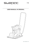
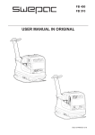
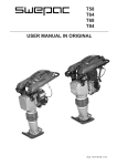
F 50
F 75
USER MANUAL
Doc: 101425A-GB 0925
Doc: 101425A-GB 0925
F50F/ 50
F75
2
F50 / F75
F 50
USE
SWEPAC F 50 / F75
is used to pack gravel and sand in connection with minor
construction work such as the basis for concrete blocks or
paving stones for gardens. The machine’s compact design
ensures good accessibility in tight spaces.
We reserve the right to modify our design and material
specifications without prior notice.
CONTENTS
Doc: 101425A-GB 0925
USE .......................................................................... 3
SAFETY INSTRUCTIONS...................................... 4
STANDARDS . ........................................................ 4
SIGNS ...................................................................... 5
TECHNICAL DATA................................................. 6
FUNCTION.............................................................. 6
TECHNICAL DESCRIPTION................................. 7
DAILY CHECKS...................................................... 8
BEFORE STARTING VANGUARD ENGINE........ 9
STARTING............................................................... 9
AFTER STARTING.................................................. 9
STOPPING............................................................... 9
OPERATING INSTRUCTIONS.............................. 9
BEFORE STARTING HONDA ENGINE.............. 10
STARTING............................................................. 10
AFTER STARTING................................................ 10
STOPPING............................................................. 10
TRANSPORTATIONS........................................... 11
3
F50F /50
F75
SAFETY INSTRUCTIONS
STANDARDS
• Before using the machine, the operator must be informed Noise
of the manufacturer’s safety instructions and instructions Measurement in accordance with the standard EN 500-4
for use.
Rev. 1:1998, Annex C:
• The machine may only be used outdoors.
• The machine may not be used if protection and safety devices are not present or not working.
•
The operator may not leave the machine unattended when the engine is on. When the vibrator is connected, the operator must be able to control the movement of the machine using the control handle and the start/stop controls. The machine may be operated only by a trained operator.
• During maintenance work or other interventions in the machine, the engine must always be off.
• Switch the engine off before adding fuel. Avoid fuel spillage and immediately wipe off any spilled fuel. Add fuel only in well ventilated areas.
• Avoid touching hot engine parts, for example the silencer.
• Before lifting the machine, check that the lifting device and its mounting are not damaged and that the rubber dampers on the base plate are undamaged and tightened.
• During transportation and storage, the fuel tank should be empty and the fuel cock switched off.
• The operator must use ear protectors when working with the machine.
In accordance with the conditions in Directive 2000/14/EC,
Annex VI, the following values are reported:
F 50
F 75
Sound pressure level
89 dB (A)
at the operator’s ears,
89 dB (A)
LpA
permitted sound
105 dB (A)
power level, L WA
105 dB (A)
Guaranteed sound
105 dB (A)
power level, L WA
105 dB (A)
As the sound pressure level at the operator’s ears exceeds
85 dB (A), ear protectors must be used during operation!
Hand/arm vibrations
The vibration acceleration was measured in accordance
with the ISO 5349 standard during operation on a graveled
surface. The measurement values were translated into
the maximum daily exposure time for regular usage. For
additional information about vibrations, please confer
the regulation AFS 2005:15 from the Swedish Work
Environment Authority, effective July 1st 2005.
F 50
F 75
Hand/armvibrations, m/s2
4,5
4,6
The maximum daily
exposure time
2,5 h
2,4 h
• The operator must ensure that no unauthorised persons are in the immediate vicinity of the machine.
Doc: 101425A-GB 0925
Exhaust emissions
F 50 meets the requirements for California ExH, EYP och
EPA PH2
F 75 meet the requirements for exhaust emissions in
acoordance with EU directive 2002/88 Euro2
4
F50
/ F75
F 50
SIGNS
Warning signs
Machine Signs
1
2
3
4
8
5
Before use, carefully read the manual and its safety instructions so that you can handle the machine safely. Ensure that
the manual is always accessible.
7
1.
2.
3.
4.
5.
6.
7.
8.
6
Manufacturer
Place, country of manufacture.
CE mark.
Model name.
Year of manufacture.
Max. engine power.
Max. weight.
Serial number.
Engine, silencer: to avoid burns or discomfort, do not touch
hot engine parts when the engine is on or when the machine
has recently been used.
Doc: 101425A-GB 0925
Belt drive: Keep hands, tools and other objects away from
the belt drive when the machine is on to avoid injury and
damage. See the safety instructions in the manual.
As the sound pressure level at the operator’s ears exceeds 85
dB (A), ear protectors must be used when working with the
machine to prevent hearing damage.
5
F50
/ F75
F 50
TECHNICAL DATA
F 50
Net weight..................................52 kg
Base plate, w x l ........................300 x 500 mm
Speed..........................................appr 25 m/min
Centrifugal force........................9 kN
Handle vibrations.......................115 Hz
Drive engine...............................Vanguard
Engine power.............................1,8 kW
Engine RPM...............................3600 RPM
Fuel tank volume........................1,6 liter
Fuel type.....................................Unleaded petrol or alkylatet
Oil quantity, crankcase...............0,4 liter
FUNCTION
The machine consists of a base plate with a vibration
element and an upper part cushioned from the base plate.
The power is transmitted from the petrol engine to the
vibration element via a V-belt.
The engine is fitted with an integrated centrifugal clutch.
On account of the direction of rotation and the position of
the vibration element at the front end of the base plate, the
vibrator moves forward under its own power. The moving
parts are well protected by a cover made of impact resistant
polythene.
F 75
Net weight..................................75 kg
Base plate, w x l ........................380 x 530 mm
Speed..........................................appr 25 m/min
Centrifugal force........................11 kN
Handle vibrations.......................94 Hz
Drive engine...............................Honda
Engine power.............................2,9 kW
Engine RPM...............................3600 RPM
Fuel tank volume........................2,5 liter
Fuel type.....................................Unleaded petrol or alkylatet
Oil quantity, crankcase...............0,6 liter
FUEL AND OIL RECOMMENDATIONS
Doc: 101425A-GB 0925
Fuel...............................Unleaded petrol or alkylate
Engine oil......................SAE10W-30
6
F50F/ 50
F75
TECHNICAL DESCRIPTION
1
3
2
5
8
9
7
10
6
4
Handle
Protective cover
Petrol engine
Rubber damper
Vibration element
Base plate
Engine plate
V-belt
Centrifugal clutch
Lifting eye
Doc: 101425A-GB 0925
1.
2.
3.
4.
5.
6.
7.
8.
9.
10.
7
F50
F 50/ F75
DAILY CHECKS
Fuel Check
Check that there is fuel in the tank. Top up if necessary.
Engine Oil Level Check
Check the oil level in the crankcase every day. The oil
must reach the edge of the filling hole when the machine is
on a level surface.
V-belt Drive
Check the tension and condition of the V-belt regularly.
Replace a damaged V-belt with the new type Z25 for
F50 and A28 for F75.
2
Air Filter Check Vanguard
The air filter must be checked at least once every working week.
When working in dusty conditions, check daily.
4
1
3
Adjustment of V-belt tension
Loosen the screws (1, 4 pcs) that hold the engine plate.
Loosen the screws (2, 3 pcs) holding the cover.
Remove the cover.
4
3
2
1
Cleaning the air filter
1. Loosen screws (1) and remove the cover (2). Clean the dust off the cover
2. Clean the pre-cleaner (3) with cleanser and water.
Saturate the precleaner in engine oil. Squeeze dry in
clean absorbent cloth.
3. Clean the cartridge (4) by tapping it gently on a flat surface.
NOTE! Renew a damaged cartridge.
4. Make sure that the aluminum plate (5) is remounted according to illustration.
5. Remount the filter unit in opposit order..
Air Filter Check Honda
The air filter must be checked at least once every
working week. When working in dusty conditions,
check daily.
1. Paper element
2. Foam plastic element
Cleaning the air filter
1. Remove the foam plastic element and the
paper element and check that they are
undamaged. Replace damaged parts.
2. Wash the foam plastic element in liquid with
a high flashpoint and let it dry properly. Dip in
engine oil and squeeze dry.
3. Strike the paper element against a hard object
a few times to loosen any dirt.
Oil/Fuel Leakage
Check every day that the engine is not leaking oil
or fuel. If a leak is discovered, the machine may
not be operated until the fault has been remedied.
See also the separate engine instructions!
8
Rubber Dampers
Check the condition of the rubber dampers (4, 4 pcs)
regularly. Replace damaged dampers.
Polyuretan Pad
A polyuretan pad is used for stone paving work to protect
against stones and ground clinker.
1
2
Doc: 101425A-GB 0925
5
Tension the V-belt by pulling the handle (3).
Tighten the screws.
Refit the cover.
F50F /50
F75
Oil level
Starting handle
Engine switch
Choke
Fuel shut-off valve
BEFORE STARTING VANGUARD ENGINE
NOTE! The machine is equipped with an oil guard, which
switches off the engine if the oil level is too low. Always
check the oil level if the machine cannot be started.
Fill up oil to the FULL-mark on the dipstick.
Also see Daily Checks on page 8.
STARTING
Set the choke to CHOKE-position.
Set the throttle lever to FAST-position.
Open the fuel shut-off valve.
Move the engine switch to position I.
Start by pulling the starting handle.
Throttle lever
OPERATING INSTRUCTIONS
The machine’s vibration elements start when the throttle is
increased. The best packing is achieved at full engine RPM.
Avoid running the engine at other RPM as there is a risk of
the clutch slipping, with abnormal wear as a result.
Thanks to its compact design and low weight, the
machine’sis very easy to manoeuvre. The design of the base
plate allows the machine to be pulled backwards without
disturbing the packed surface. The machine’s vibration
element stops when the throttle is switched to idle.
The machine is only designed to be used outdoors. Work
with the machine in daylight or other adequate lighting.
Ballast must be wetted or naturally damp. All other use is
discouraged.
AFTER STARTING
Open the choke gradually.
Run the engine warm for around 5 minutes.
STOPPING
Switch the engine to idle and let it run for a few minutes.
Doc: 101425A-GB 0925
Shut off the engine, by setting the red engine switch to
position O.
9
F50
F 50/ F75
Off
On
Oil level
Off
On
Fuel cock
Engine power switch
Idle
Full RPM
Throttle lever
Closed
Open
Choke
BEFORE STARTING HONDA ENGINE
AFTER STARTING
See Daily Checks on page 8.
Switch the throttle lever to idle.
Open the choke gradually.
STARTING
Switch the engine power switch to “on”. Open the fuel cock.
Switch the throttle lever to 1/3 of full RPM.
Adjust the choke. If the engine is cold, close the choke completely. Do not use the choke if the engine is warm or if the
air temperature is high.
STOPPING
Switch the engine to idle and let it run for a few minutes.
Switch the engine power switch to “off”.
Close the fuel cock.
Doc: 101425A-GB 0925
Start by pulling the starting handle. Pull it first until the
mechanism engages. Then pull it hard and fast.
Run the engine warm for around 5 minutes.
10
F50F /50
F75
TRANSPORTATION
It is easy to remove the handle witout tools, and the boot of
a standard car is sufficient to transport the machine.
Lifting by hand
Remove the handle by tilting it forward and pulling the
shafts apart.
Move the handle from side to side so that the dowels let go.
Transport locking
Secure the machine with straps accorrding to illustration
during transportation
Note! Secure it by the base plate and not the rubbercushioned upper part.
Caution!The machine must be lifted by 2 persons!
Lift by means of the handle on the back and the front edge
of the machine.
Doc: 101425A-GB 0925
Lifting with crane
Tilt the handle forward.
Fit a lifting sling to the lifting eye and thread the lifting
sling between the shafts of the handle, see illustartion
below.
11
SWEPAC INTERNATIONAL AB
Address Box 132, 341 23 Ljungby, Sweden, tel. +46 (0)372-156 00, fax +46 (0)372-837 41, E-mail [email protected],
Internet www.swepac.se