1
FB 465
USER MANUAL
Dok: 101490-GB 0810
Dok: 101490-GB 0810
FB 465
FB 465
USE
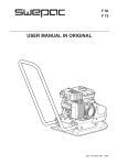
SWEPAC FB 465
is used to pack ballast under foundations, in connection with road
building, in trenches, etc. On account of the forward/reverse function, the machine is very suitable for packing in tight spaces and as
a complement to larger packing equipment. The infinitely variable
speed control makes it possible to move with great precision and to
pack without moving.
CONTENTS
Dok: 101490-GB 0810
USE ...........................................................................3
SAFETY INSTRUCTIONS . ....................................4
STANDARDS . .........................................................4
SIGNS .......................................................................5
TECNICAL DATA.....................................................6
METHOD OF OPERATION ....................................6
TECHNICAL DESCRIPTION..................................7
DAILY CHECKS.......................................................8
BEFORE STARTING ...............................................9
STARTING................................................................9
STOPPING ...............................................................9
OPERATING INSTRUCTIONS ............................10
TRANSPORTATION . ............................................10
FB 465
SAFETY INSTRUCTIONS
STANDARDS
• Before using the machine, the operator must be informed of the manufacturer’s safety instructions and instructions for use.
Noise
Measurement in accordance with the standard EN 500-4
Rev. 1:1998, Annex C:
• The machine may only be used outdoors.
In accordance with the conditions in Directive 2000/14/EC,
Annex VI, the following values are reported:
• The machine may not be used if protection and safety devices are not present or not working.
• The operator may not leave the machine unattended when the engine is on. When the vibrator is connected, the operator must be able to control the movement of the machine using the control handle and the start/stop controls. The machine may be operated only by a trained operator.
• During maintenance work or other interventions in the machine, the engine must always be off.
• Switch the engine off before adding fuel. Avoid fuel spillage and immediately wipe off any spilled fuel. Add fuel only in well ventilated areas.
• Avoid touching hot engine parts, for example the silencer.
• Before lifting the machine, check that the lifting device and its mounting are not damaged and that the rubber dampers on the base plate are undamaged and tightened.
• During transportation and storage, the fuel tank should be empty and the fuel cock switched off.
• When the machine is parked, ensure that it cannot tip over. The machine may not incline more than 20º.
• The operator must use ear protectors when working with the machine.
• The operator must ensure that no unauthorised persons are in the immediate vicinity of the machine.
Sound pressure
level at the oper-
ator’s ears, LpA
FB 465
93 dB (A)
Permitted sound
power level, L WA
108 dB (A)
Guaranteed sound
power level, L WA
108 dB (A)
As the sound pressure level at the operator’s ears exceeds
85 dB (A), ear protectors must be used during operation!
Hand/arm vibrations
The vibration acceleration was measured in accordance
with the ISO 5349 standard during operation on a surface
of macadam. The measurement values were translated
into the maximum daily exposure time for regular usage.
For additional information about vibrations, please confer
the regulation AFS 2005:15 from the Swedish Work
Environment Authority, effective July 1st 2005.
FB 465
Hand/arm
vibrations m/s2
2,6
The maximum
daily exposure
time
7,4 h
Dok: 101490-GB 0810
Exhaust Emissions
The FB 465 meets the requirements for exhaust emissions in
accordance with US-EPA stage 2.
FB 465
SIGNS
Warning Signs
Machine Signs
1
2
3
4
8
Before use, carefully read the manual and its safety instructions so that you can handle the machine safely. Ensure that
the manual is always accessible.
5
7
1.
2.
3.
4.
5.
6.
7.
8.
6
Manufacturer
Place, country of manufacture.
CE mark.
Model name.
Year of manufacture.
Max. engine power.
Max. weight.
Serial number.
Engine, silencer: to avoid burns or discomfort, do not touch
hot engine parts when the engine is on or when the machine
has recently been used.
Dok: 101490-GB 0810
As the sound pressure level at the operator’s ears exceeds 85
dB (A), ear protectors must be used when working with the
machine to prevent hearing damage.
FB 465
TECHNICAL DATA
FB 465
Net weight..................................465 kg
Base plate, w x l.........................700 x 1080 mm
Speed..........................................approximately 25 m/min
Permitted inclination . ...............20°
Centrifugal force........................60,000 N
Vibration frequency...................70 Hz
Drive engine...............................Yanmar L 100AE
Engine power.............................7.35 kW
Engine RPM...............................3600 RPM
Fuel tank volume........................5.5 liter
Fuel type.....................................Diesel
Hydraulic oil volume.................38 liter
Battery capacity.........................40 Ah
Generator power.........................180 W (15 A)
Oil quantity, crankcase...............1,65 liter
FUEL and OIL RECOMMENDATIONS
METHOD OF OPERATION
The machine consists of a base plate with a vibration
element and an upper part cushioned from the base plate.
The cushioning between the base plate and the upper part
consists of four rubber dampers. The upper part, on which
the drive engine is mounted, is also designed as a hydraulic
oil tank. The control handle is placed on the upper part and
cushioned with rubber dampers. The vibration element is
driven and the direction of travel is changed by means of hydraulics. The hydraulic pump, mounted on the diesel engine,
supplies a hydraulic motor on the vibration element with an
oil flow. The vibration element consist of two shafts on roller
bearings with bias weights that are connected to gear wheels
that rotate in opposite directions. One gear wheel can rotate
on its shaft by means of a hydraulic cylinder. This changes
the mutual phase positions of the eccentric weights and the
direction of travel of the machine, and the speed is changed
infinitely variably. All parts are well protected against damage in connection with use and transportation by a sturdy
protective frame with a hood of impact-resistant polythene.
Dok: 101490-GB 0810
Fuel............................................Diesel
Engine oil...................................SAE10W-30
Hydraulic oil..............................Viscosity Grade ISO VG 32
FB 465
TECHNICAL DESCRIPTION
FB 465
1
6
2
3
7
8
4
5
14
13
12
11
Left side view
10
9
15
16
Right side view
Protective hood
Lifting eye
Diesel engine
Control panel
Hydraulic tank
Control handle
Forward/reverse control
Vibrator and handle heating switch
9.
10.
11.
12.
13.
14.
15.
16.
Base plate
Rubber damper
Vibration element
Air filter
Hydraulic pump
Gas shock absorber
Hydraulic oil filter
Transport locking device
Dok: 101490-GB 0810
1.
2.
3.
4.
5.
6.
7.
8.
FB 465
DAILY CHECKS
Fuel Check
Check that there is fuel in the tank. Top up if necessary.
Engine Oil Level Check
Check the oil level in the crankcase every day. The oil must
reach the edge of the filling hole when the machine is on a
level surface.
Oil/Fuel Leakage
Check every day that the engine is not leaking oil or fuel. If
a leak is discovered, the machine may not be operated until
the fault has been remedied.
Hydraulic Oil Level Check
Check every day that the hydraulic connections do not
leak or wear during operation. Check the oil level with the
dipstick on the top of the tank. The level must be between
“MIN” and “MAX”.
Air Filter Check
The air filter must be checked at least once every working
week.
1
2
3
4
1. Filter housing
2. Safety cartridge
3. Filter element
4. Cap
Vibration Element
Check regularly that there is no oil leak. If you suspect a
leak, check the level at the level screw on the vibration element. If necessary, add oil up to the lower edge of the level
hole when the vibrator is horizontal. Seal any leaks. Note!
Machines must never be operated if a leak is suspected.
Cleaning
1. Remove the cap and empty out the dust which has
collected. Wipe the cap with a damp cloth.
2. Carefully remove the filter element and wipe the inside of the filter housing clean.
3. Blow the filter clean with dry compressed air, max. 5 bar, from the inside until no more dust comes out.
Throw the filter element away:
− if it has been cleaned five times.
− if it is damaged.
− after 1000 operating hours or maximum 12 months.
Rubber Dampers
Check the condition of the rubber dampers regularly. Replace damaged dampers.
Dok: 101490-GB 0810
Safety Cartridge
This is normally replaced after around 3000 operating hours
or if the main filter is damaged.
To replace it, remove the filter set as described above and fit
a new safety cartridge.
FB 465
Closed
Open
Fuel cock
1
Main power switch
2
Decompression handle
3
Instrument panel with;
1. Engine power switch
2. Control lamps for charging and oil pressure
3. Throttle lever
BEFORE STARTING
See Daily Checks on page 8.
STARTING
Open the hood.
Open the fuel cock.
Switch the main power switch, located on the instrument
panel inside the protective cover, to the position “I”.
Close the hood.
Note! The vibration power switch on the handle must
be in the position “vibration off” (red/green marking).
Otherwise the machine cannot be started.
Switch the throttle lever (3) to the full RPM position (green
marking).
Dok: 101490-GB 0810
Start the engine with the power switch (1). Place the knob
in the central position and check that the charging and oil
pressure lamps (2) light up. Then press the power switch
down (green marking).
Vibration power switch and
handle heating
In very cold weather or if the battery capacity is low for
a different reason, starting can be facilitated using the
decompression handle in connection with the valve housing.
Press the lever down and hold it down until the flywheel has
reached its maximum RPM. Run the engine warm for around
5 minutes.
STOPPING
Switch the throttle lever (3) to idle and let the engine run for
a few minutes.
Press the engine power switch (1) upwards (red marking).
Stop the engine by moving the throttle lever to the stop position (red marking).
At the End of the Day
Open the hood.
Switch off the main power switch, “O” position.
Close the fuel cock.
Close the hood.
Note! Never run the starter motor for longer than 10 seconds
at a time. If the engine does not start, wait 15 seconds before
trying to start it again.
FB 465
OPERATING INSTRUCTIONS
TRANSPORTATION
The vibrator is started and stopped with the power switch on
the handle.
When the control hoop on the handle is moved backwards,
the machine reverses and when the hoop is moved forwards,
the machine moves forwards. The speed is controlled by
how long the control hoop is activated.
The machine is fitted with a lifting hawser that can be folded
in under the hood when it is not in use.
The machine is only designed to be used outdoors. Work
with the machine in daylight or other adequate lighting.
Ballast must be wetted or naturally damp. All other use is
discouraged.
Note! When moving up a slope, the machine should be
reversed.
The machine may not incline more than 20º when in use or
parked.
Check before lifting that the lifting eye and its mounting
on the machine are undamaged. Check also that the base
plate’s rubber dampers are undamaged and firmly attached.
For transportation by vehicle, the handle must be folded
forwards and locked with the transport locking device. The
machine must then be secured with, for example, approved
straps. Note! Secure it by the base plate and not the rubbercushioned upper part.
Dok: 101490-GB 0810
Handle Heating
For increased comfort, the machine has an electrically heated handle. The handle heating is activated with the power
switch on the handle and can only be used when the vibrator
is connected, which prevents the heating coil from discharging the battery when the machine is not being used.
10
Dok: 101490-GB 0810
FB 465
11