1
Hitachi Microcomputer Support Software
SuperH RISC Engine
Assembler
User’s Manual
ADE-702-090C
Rev. 4.0
11/4/98
Hitachi, Ltd.
McS-Setsu
Cautions
1. Hitachi neither warrants nor grants licenses of any rights of Hitachi’s or any third party’s
patent, copyright, trademark, or other intellectual property rights for information contained in
this document. Hitachi bears no responsibility for problems that may arise with third party’s
rights, including intellectual property rights, in connection with use of the information
contained in this document.
2. Products and product specifications may be subject to change without notice. Confirm that you
have received the latest product standards or specifications before final design, purchase or
use.
3. Hitachi makes every attempt to ensure that its products are of high quality and reliability.
However, contact Hitachi’s sales office before using the product in an application that
demands especially high quality and reliability or where its failure or malfunction may directly
threaten human life or cause risk of bodily injury, such as aerospace, aeronautics, nuclear
power, combustion control, transportation, traffic, safety equipment or medical equipment for
life support.
4. Design your application so that the product is used within the ranges guaranteed by Hitachi
particularly for maximum rating, operating supply voltage range, heat radiation characteristics,
installation conditions and other characteristics. Hitachi bears no responsibility for failure or
damage when used beyond the guaranteed ranges. Even within the guaranteed ranges,
consider normally foreseeable failure rates or failure modes in semiconductor devices and
employ systemic measures such as fail-safes, so that the equipment incorporating Hitachi
product does not cause bodily injury, fire or other consequential damage due to operation of
the Hitachi product.
5. This product is not designed to be radiation resistant.
6. No one is permitted to reproduce or duplicate, in any form, the whole or part of this document
without written approval from Hitachi.
7. Contact Hitachi’s sales office for any questions regarding this document or Hitachi
semiconductor products.
Preface
This manual describes the SuperH RISC Engine Assembler (hereafter referred to as the
assembler), which supports development of programs for Hitachi SuperH RISC engine family
(hereafter referred to as microprocessor).
This manual is organized as follows:
Overview:
Gives an overview of the functions of the assembler.
Programmer's Guide: Describes the assembly language syntax and programming techniques.
User's Guide:
Describes the use (invocation) of the assembler program itself and the
command line options.
Appendix:
Describes assembler limitations and error messages.
Read this manual and fully understand its mechanisim before use of the assembler.
For information concerning the related hardware and software, read the corresponding manuals
and understand their mechanisims before use.
Rev. 4.0, 09/98, page v of 15
Notes:
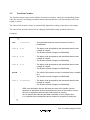
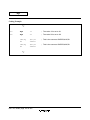
• The following symbols have special meanings in this manual.
<item>: <specification item>
∆:
Blank space(s) or tab(s)
%:
The OS prompt (indicates the input waiting state)
(RET):
Press the Return (Enter) key.
... :
The preceding item can be repeated.
[ ]:
The enclosed item is optional (i.e., can be omitted.)
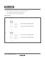
• Numbers are written as follows in this manual.
Binary:
A prefix of “ B' ” is used.
Octal:
A prefix of “ Q' ” is used.
Decimal:
A prefix of “ D' ” is used.
Hexadecimal: A prefix of “ H' ” is used.
However, when there is no specification, the number without a prefix is decimal.
Windows95 and WindowsNT are registered trademarks of Microsoft Corporation.
UNIX is a registered trademark in the United States and other countries, licensed exclusively
through X/Open Company Limited.
SPARC is a CPU and workstation administered by SPARC International, Inc.
HP9000/700 series is a trademark of Hewlett-Packard Company.
PC-9800 series is a trademark of NEC Corporation.
IBM PC is a registered trademark of International Business Machines Corporation.
Rev. 4.0, 09/98, page vi of 15
Contents
Overview
Section 1
Overview ...........................................................................................................
3
Section 2
Relationships between the Software Development Support
Tools ...................................................................................................................
5
Programmer’s Guide
Section 1
1.1
1.2
1.3
1.4
1.5
1.6
1.7
1.8
Program Elements ..........................................................................................
Source Statements .............................................................................................................
1.1.1 Source Statement Structure ..................................................................................
1.1.2 Coding of Source Statements ...............................................................................
1.1.3 Coding of Source Statements across Multiple Lines............................................
Reserved Words ................................................................................................................
Symbols.............................................................................................................................
1.3.1 Functions of Symbols...........................................................................................
1.3.2 Coding of Symbols...............................................................................................
Constants ...........................................................................................................................
1.4.1 Integer Constants..................................................................................................
1.4.2 Character Constants..............................................................................................
1.4.3 Floating-Point Constants ......................................................................................
1.4.4 Fixed-Point Constants ..........................................................................................
Location Counter...............................................................................................................
Expressions........................................................................................................................
1.6.1 Elements of Expression ........................................................................................
1.6.2 Operation Precedence...........................................................................................
1.6.3 Detailed Description on Operation.......................................................................
1.6.4 Notes on Expressions ...........................................................................................
Character Strings ...............................................................................................................
Local Label........................................................................................................................
1.8.1 Local Label Functions..........................................................................................
1.8.2 Description Method of Local Label .....................................................................
1.8.3 Scope of Local Labels ..........................................................................................
Section 2
2.1
11
11
11
13
15
16
16
16
18
19
19
20
21
26
29
31
31
33
36
39
40
42
42
43
43
Basic Programming Knowledge................................................................. 45
Sections ............................................................................................................................. 45
2.1.1 Section Types by Usage ....................................................................................... 45
2.1.2 Absolute Address Sections and Relative Address Sections.................................. 50
Rev. 4.0, 09/98, page vii of 15
2.2
2.3
2.4
Absolute and Relative Values ...........................................................................................
2.2.1 Absolute Values ...................................................................................................
2.2.2 Relative Values ....................................................................................................
Symbol Definition and Reference .....................................................................................
2.3.1 Symbol Definition ................................................................................................
2.3.2 Symbol Reference ................................................................................................
Separate Assembly ............................................................................................................
2.4.1 Separate Assembly ...............................................................................................
2.4.2 Declaration of Export Symbols and Import Symbols...........................................
Section 3
3.1
3.2
Executable Instructions .................................................................................
Overview of Executable Instructions ................................................................................
Notes on Executable Instructions ......................................................................................
3.2.1 Notes on the Operation Size.................................................................................
3.2.2 Notes on Delayed Branch Instructions .................................................................
3.2.3 Notes on Address Calculations.............................................................................
Section 4
4.1
4.2
61
61
67
67
84
86
DSP Instructions ............................................................................................. 91
Program Contents ..............................................................................................................
4.1.1 Source Statements ................................................................................................
4.1.2 Parallel Operation Instructions.............................................................................
4.1.3 Data Move Instructions ........................................................................................
4.1.4 Coding of Source Statements Across Multiple Lines...........................................
DSP Instructions................................................................................................................
4.2.1 DSP Operation Instructions..................................................................................
4.2.2 Data Move Instructions ........................................................................................
Section 5
5.1
5.2
52
52
52
53
53
55
57
57
58
91
91
92
93
94
95
95
99
Assembler Directives..................................................................................... 103
Overview of the Assembler Directives.............................................................................. 103
Assembler Directive Reference ......................................................................................... 105
5.2.1 Target CPU Assembler Directive......................................................................... 105
.CPU .................................................................................................................... 106
5.2.2 Section and Location Counter Assembler Directives........................................... 108
.SECTION........................................................................................................... 109
.ORG .................................................................................................................... 114
.ALIGN ............................................................................................................... 116
5.2.3 Symbol Handling Assembler Directives .............................................................. 118
.EQU .................................................................................................................... 119
.ASSIGN ............................................................................................................. 121
.REG .................................................................................................................... 123
.FREG.................................................................................................................. 125
5.2.4 Data and Data Area Reservation Assembler Directives ....................................... 127
.DATA.................................................................................................................. 128
Rev. 4.0, 09/98, page viii of 15
5.2.5
5.2.6
5.2.7
5.2.8
.DATAB ............................................................................................................... 130
.SDATA ............................................................................................................... 133
.SDATAB ............................................................................................................. 135
.SDATAC ............................................................................................................. 138
.SDATAZ ............................................................................................................. 140
.FDATA ............................................................................................................... 142
.FDATAB ............................................................................................................. 144
.XDATA ............................................................................................................... 147
.RES .................................................................................................................... 149
.SRES.................................................................................................................. 152
.SRESC ............................................................................................................... 154
.SRESZ ............................................................................................................... 156
.FRES.................................................................................................................. 158
Export and Import Assembler Directives ............................................................. 160
.EXPORT ............................................................................................................. 161
.IMPORT ............................................................................................................. 163
.GLOBAL ............................................................................................................. 165
Object Module Assembler Directives .................................................................. 167
.OUTPUT ............................................................................................................. 168
.DEBUG ............................................................................................................... 171
.ENDIAN ............................................................................................................. 173
.LINE.................................................................................................................. 176
Assemble Listing Assembler Directives............................................................... 178
.PRINT ............................................................................................................... 179
.LIST.................................................................................................................. 181
.FORM.................................................................................................................. 185
.HEADING........................................................................................................... 187
.PAGE.................................................................................................................. 189
.SPACE ............................................................................................................... 191
Other Assembler Directives ................................................................................. 193
.PROGRAM........................................................................................................... 194
.RADIX ............................................................................................................... 196
.END .................................................................................................................... 198
Section 6
File Inclusion Function ................................................................................. 201
.INCLUDE........................................................................................................... 202
Section 7
Conditional Assembly Function ................................................................. 205
7.1
Overview of the Conditional Assembly Function ............................................................. 205
7.1.1 Preprocessor variables.......................................................................................... 205
7.1.2 Replacement Symbols .......................................................................................... 206
7.1.3 Conditional Assembly .......................................................................................... 207
7.1.4 Iterated Expansion................................................................................................ 209
Rev. 4.0, 09/98, page ix of 15
7.2
7.1.5 Conditional Iterated Expansion ............................................................................ 210
Conditional Assembly Directives...................................................................................... 211
.ASSIGNA........................................................................................................... 212
.ASSIGNC........................................................................................................... 215
.DEFINE ............................................................................................................. 217
.AIF, .AELIF, .AELSE, .AENDI ........................................................... 219
.AIFDEF, .AELSE, .AENDI....................................................................... 222
.AREPEAT, .AENDR........................................................................................ 224
.AWHILE, .AENDW .......................................................................................... 226
.AERROR ............................................................................................................. 229
.EXITM ............................................................................................................... 231
.ALIMIT ............................................................................................................. 233
Section 8
8.1
8.2
8.3
8.4
8.5
Overview of the Macro Function ...................................................................................... 235
Macro Function Directives ................................................................................................ 237
.MACRO, .ENDM............................................................................................... 238
.EXITM ............................................................................................................... 241
Macro Body....................................................................................................................... 243
Macro Call......................................................................................................................... 247
Character String Manipulation Functions.......................................................................... 249
.LEN .................................................................................................................... 250
.INSTR ............................................................................................................... 252
.SUBSTR ............................................................................................................. 254
Section 9
9.1
9.2
9.3
9.4
9.5
9.6
9.7
Macro Function ............................................................................................... 235
Automatic Literal Pool Generation Function ......................................... 257
Overview of Automatic Literal Pool Generation............................................................... 257
Extended Instructions Related to Automatic Literal Pool Generation............................... 258
Size Mode for Automatic Literal Pool Generation............................................................ 258
Literal Pool Output............................................................................................................ 260
9.4.1 Literal Pool Output after Unconditional Branch .................................................. 261
9.4.2 Literal Pool Output to the .POOL Location ......................................................... 262
Literal Sharing................................................................................................................... 264
Literal Pool Output Suppression ....................................................................................... 266
Notes on Automatic Literal Pool Output........................................................................... 267
Section 10 Automatic Repeat Loop Generation Function ....................................... 271
10.1
10.2
10.3
10.4
10.5
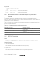
Overview of Automatic Repeat Loop Generation Function .............................................. 271
Extended Instructions of Automatic Repeat Loop Generation Function........................... 272
REPEAT Description ........................................................................................................ 272
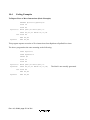
Coding Examples .............................................................................................................. 274
Notes on the REPEAT Extended Instruction .................................................................... 277
Rev. 4.0, 09/98, page x of 15
User’s Guide
Section 1
1.1
1.2
1.3
Executing the Assembler .............................................................................. 281
Command Line Format ..................................................................................................... 281
File Specification Format .................................................................................................. 282
SHCPU Environment Variable.......................................................................................... 283
Section 2
2.1
2.2
Command Line Options................................................................................ 285
Overview of Command Line Options ............................................................................... 285
Command Line Option Reference..................................................................................... 287
2.2.1 Target CPU Command Line Option..................................................................... 287
–CPU .................................................................................................................... 288
2.2.2 Object Module Command Line Options .............................................................. 289
–OBJECT, –NOOBJECT................................................................................... 290
–DEBUG, –NODEBUG........................................................................................ 292
–ENDIAN ............................................................................................................. 294
2.2.3 Assembly Listing Command Line Options .......................................................... 295
–LIST, –NOLIST ............................................................................................ 296
–SOURCE, –NOSOURCE................................................................................... 298
–CROSS_REFERENCE, –NOCROSS_REFERENCE........................................ 300
–SECTION, –NOSECTION .............................................................................. 302
–SHOW, –NOSHOW ............................................................................................ 304
–LINES ............................................................................................................... 306
–COLUMNS........................................................................................................... 307
2.2.4 File Inclusion Function Command Line Option................................................... 308
–INCLUDE........................................................................................................... 309
2.2.5 Conditional Assembly Command Line Options................................................... 310
–ASSIGNA........................................................................................................... 311
–ASSIGNC........................................................................................................... 313
–DEFINE ............................................................................................................. 315
2.2.6 Assembler Execution Command Line Option...................................................... 316
–EXPAND ............................................................................................................. 317
–ABORT ............................................................................................................... 318
2.2.7 Japanese Character Description Command Line Options .................................... 319
–SJIS.................................................................................................................. 320
–EUC .................................................................................................................... 321
–OUTCODE........................................................................................................... 322
2.2.8 Automatic Literal Pool Generation Command Line Option................................. 323
–AUTO_LITERAL............................................................................................... 324
2.2.9 Command Line Input Command Line Option...................................................... 326
–SUBCOMMAND ................................................................................................... 327
Rev. 4.0, 09/98, page xi of 15
2.2.10 Floating-Point Data Command Line Options....................................................... 329
–ROUND ............................................................................................................... 330
–DENORMALIZE ................................................................................................. 332
Appendix
Appendix A Limitations and Notes on Programming ............................................... 337
Appendix B Sample Program ........................................................................................... 338
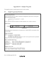
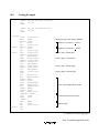
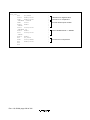
B.1
B.2
Sample Program Specifications......................................................................................... 338
Coding Example ................................................................................................................ 339
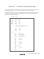
Appendix C Assemble Listing Output Example ......................................................... 341
C.1
C.2
C.3
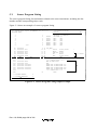
Source Program Listing..................................................................................................... 342
Cross-Reference Listing .................................................................................................... 344
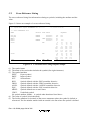
Section Information Listing............................................................................................... 345
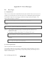
Appendix D Error Messages ............................................................................................. 346
D.1
D.2
Error Types........................................................................................................................ 346
Error Message Tables........................................................................................................ 349
Appendix E Differences from Version 3.1 ................................................................... 371
E.1
E.2
E.3
E.4
E.5
CPU .................................................................................................................................. 371
Object Format.................................................................................................................... 371
Constants ........................................................................................................................... 372
Changed Assembler Directives ......................................................................................... 372
Added Command Line Options......................................................................................... 372
Appendix F ASCII Code Table........................................................................................ 374
Rev. 4.0, 09/98, page xii of 15
Figures
Overview
Figure 1-1
Figure 2-1
Function of the Assembler......................................................................................
Relationships between the Software Development Support Tools .........................
Programmer’s Guide
Figure 2-1 Memory Reservation of Common Section .............................................................
Figure 2-2 Data Structure Example Using Dummy Section ....................................................
Figure 2-3 Meaning of the Terms Forward and Backward ......................................................
Figure 2-4 Meaning of the Term External................................................................................
Figure 2-5 Relationship between the Changed Range of the Source Program and
the Range of the Program that must be Reassembled .............................................
Figure 3-1 Address Calculation Example (Normal Case) ........................................................
Figure 3-2 Address Calculation Example (When the Value of PC Differs Due to a Branch) ..
Figure 3-3 Address Calculation Example (When Microprocessor Corrects
the Value of PC) ....................................................................................................
Figure 3-4 Address Calculation Example (When Microprocessor Does Not Correct
the Value of PC) .....................................................................................................
Appendix
Figure C-1
Figure C-2
Figure C-3
4
6
47
49
55
55
57
86
87
88
88
Source Program Listing Output Example ............................................................... 342
Cross-Reference Listing Output Example .............................................................. 344
Section Information Listing Output Example......................................................... 345
Rev. 4.0, 09/98, page xiii of 15
Tables
Programmer’s Guide
Table 1-1
Floating-Point Data Types...................................................................................... 22
Table 1-2
Data Types and Numerical Value Ranges (Absolute Value).................................. 23
Table 1-3
Data Format Size .................................................................................................... 24
Table 1-4
Floating-Point Representation for Each Data Type ................................................ 25
Table 1-5
Operators ................................................................................................................ 31
Table 1-6
Operator Precedence and Association Rules .......................................................... 33
Table 1-7
Even/Odd Operations.............................................................................................. 38
Table 3-1
Addressing Modes .................................................................................................. 62
Table 3-2
Allowed Displacement Values................................................................................ 64
Table 3-3
Allowed Immediate Values .................................................................................... 66
Table 3-4
SH-1 Executable Instruction and Operation Size Combinations ........................... 67
Table 3-5
SH-2 Executable Instruction and Operation Size Combinations ........................... 73
Table 3-6
SH-2E Executable Instruction and Operation Size Combinations ......................... 74
Table 3-7
SH-3 Executable Instruction and Operation Size Combinations ........................... 76
Table 3-8
SH-3E Executable Instruction and Operation Size Combinations ......................... 78
Table 3-9
SH-4 Executable Instruction and Operation Size Combinations ........................... 80
Table 3-10 SH-DSP, SH3-DSP Executable Instruction and Operation Size Combinations .... 83
Table 3-11 Relationship between Delayed Branch Instructions and Delay Slot Instructions ... 85
Table 4-1
DSP Instructions in Mnemonic............................................................................... 95
Table 4-2
Addressing Modes for DSP Operation Instructions................................................ 95
Table 4-3
Registers that Can Be Specified in DSP Register Direct Addressing Mode........... 96
Table 4-4
Ranges of Immediate Data...................................................................................... 96
Table 4-5
DSP Operation Instructions .................................................................................... 98
Table 4-6
Data Move Instructions in Mnemonic .................................................................... 99
Table 4-7
Addressing Modes of Data Move Instructions ....................................................... 100
Table 4-8
Registers that Can Be Specified in Addressing Modes for Data Move
Instructions ............................................................................................................. 101
Table 4-9
Data Move Instructions........................................................................................... 102
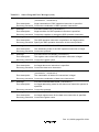
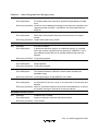
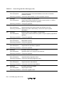
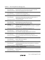
Table 5-1
Assembler Directives.............................................................................................. 103
Table 9-1
Extended Instructions and Expanded Results ......................................................... 258
Table 9-2
Data Move Instructions and Size Mode.................................................................. 258
Table 9-3
Instructions Selected in Size Selection Mode......................................................... 259
Table 10-1 Repeat Loop Instructions and Address Setting ....................................................... 271
Table 10-2 Extended Instructions and Expanded Results ......................................................... 272
User’s Guide
Table 2-1
Command Line Options.......................................................................................... 285
Rev. 4.0, 09/98, page xiv of 15
Appendix
Table A-1
Table D-1
Table D-2
Table D-3
Table D-4
Table E-1
Table E-2
Table F-1
Limitations and Notes on Programming ................................................................. 337
Command Error Messages...................................................................................... 349
Source Program Error Messages............................................................................. 350
Source Program Warning Messages ....................................................................... 362
Fatal Error Messages .............................................................................................. 368
Changed Assembler Directives and Statements...................................................... 372
Added Command Line Options .............................................................................. 372
ASCII Code Table .................................................................................................. 374
Rev. 4.0, 09/98, page xv of 15
Overview
Section 1 Overview
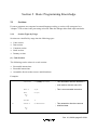
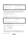
The assembler converts source programs written in assembly language into a format that can be
handled by microprocessors, and outputs the result as an object module. Also, the results of the
assembly processing are output as an assemble listing.
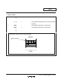
This assembler provides the following functions to support efficient program development:
• Assembler directives
Give the assembler various instructions.
• File inclusion function
Includes files into a source file.
• Conditional assembly function
Selects source statements to be assembled or repeats assembly according to a specified
condition.
• Macro function
Gives a name to a sequence of statements and defines it as one instruction.
• Automatic literal pool generation function
Interprets data transfer instructions MOV.W #imm, MOV.L #imm, and MOVA #imm that are
not provided by the SuperH RISC engine family as extended instructions and expands them
into microprocessor executable instructions and constant data (literals).
• Automatic repeat loop generation function
Interprets instruction REPEAT that is not provided by the SH-DSP as an extended instruction
and expands it into SH-DSP repeat loop instructions (LDRS, LDRE, and SETRC) that control
the repeat loop characteristic of the SH-DSP.
Rev. 4.0, 09/98, page 3 of 391
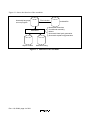
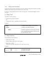
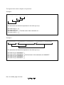
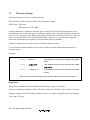
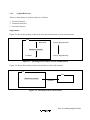
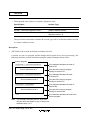
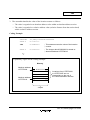
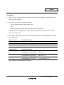
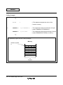
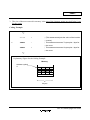
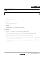
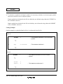
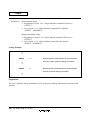
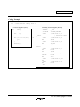
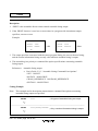
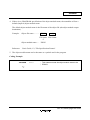
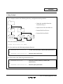
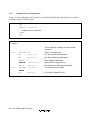
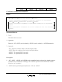
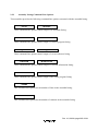
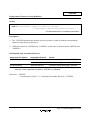
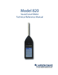
Figure 1-1 shows the function of the assembler.
Assembly-language
source program
File inclusion
Assembler
Object module
• Assembler directives
• Conditional assembly
• Macro
• Automatic literal pool generation
• Automatic repeat loop generation
Assemble listing
Figure 1-1 Function of the Assembler
Rev. 4.0, 09/98, page 4 of 391
Included file
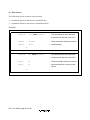
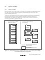
Section 2 Relationships between the Software
Development Support Tools
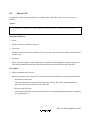
In addition to the assembler, software development support tools, such as the C/C++ compiler,
linkage editor, librarian, object converter, and simulator/debugger are available for the SuperH
RISC engine family.
These tools assist in the efficient development of application software.
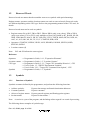
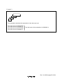
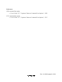
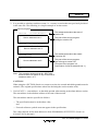
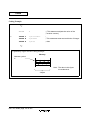
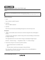
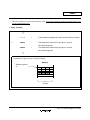
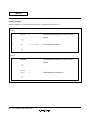
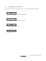
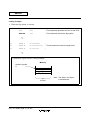
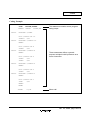
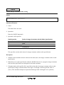
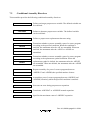
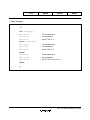
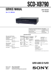
Figure 2-1 shows the relationships between the software development support tools.
Rev. 4.0, 09/98, page 5 of 391
Editor
C/C++-language
source program
Assembly-language
source program
C/C++ compiler
Assembler
Librarian
CPU information analyzer
Object
module
CPU
information
file
Linkage editor
Library
file
Load
module
Object converter
Simulator/debugger
S-type-format
load module
Figure 2-1 Relationships between the Software Development Support Tools
Rev. 4.0, 09/98, page 6 of 391
Supplement:
Use a general purpose editor (a text editor) to edit source programs.
The C/C++ compiler converts programs written in the C/C++ language into either object modules
or assembly-language source programs.
The librarian converts object modules and relocatable load modules into library files. We
recommend handling processing that is common to multiple programs as a library file. (This has
several advantages, including allowing modules to be easily managed.)
The linkage editor links together object modules and library files to produce load modules
(executable programs).
The object converter converts load modules into the S-type format. (The S-type format is a
standard load module format.)
The simulator/debugger assists debugging microprocessor software.
Load modules created by this development support system can be input to several types of
emulator. (Emulators are systems for debugging microprocessor system hardware and software.)
Also, S-type-format load modules can be input into most EPROM programmers.
Rev. 4.0, 09/98, page 7 of 391
Programmer’s Guide
Section 1 Program Elements
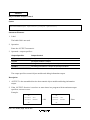
1.1
Source Statements
?If source programs are compared to natural language writing, a source statement will correspond
to "a sentence." The "words" that make up a source statement are reserved words and symbols.
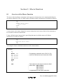
1.1.1
Source Statement Structure
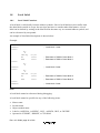
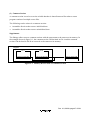
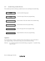
The following shows the structure of a source statement.
[<label>] [∆<operation>[∆<operand(s)>]] [<comment>]
Example:
~
LABEL1:
MOV.L
@R0,R1
; This is an example of a source statement.
~
Comment
Operands
Operation
Label
Rev. 4.0, 09/98, page 11 of 391
(1) Label
A symbol or a local symbol is written as a tag attached to a source statement.
A symbol is a name defined by the programmer.
(2) Operation
The mnemonic of an executable instruction, an extended instruction, a DSP instruction, an
assembler directive, or a directive statement is written as the operation.
Executable instructions must be microprocessor instructions.
Extended instructions are instructions that are expanded into executable instructions and constant
data (literals) or several executable instructions. For details, refer to Programmer's Guide, 9,
"Automatic Literal Pool Generation Function" and 10, "Automatic Repeat Loop Generation
Function".
DSP instructions are instructions that control the DSP of the SH-DSP microprocessor. For details,
refer to Programmer's Guide, 4, "DSP Instructions."
Assembler directives are instructions that give directions to the assembler.
Directive statements are used for file inclusion, conditional assembly, and macro functions. For
details on each of these functions, refer to Programmer's Guide, 6, "File Inclusion Function", 7,
"Conditional Assembly Function", or 8, "Macro Function".
(3) Operand
The object(s) of the operation's execution are written as the operand.
The number of operands and their types are determined by the operation. There are also operations
which do not require any operands.
(4) Comment
Notes or explanations that make the program easier to understand are written as the comment.
Rev. 4.0, 09/98, page 12 of 391
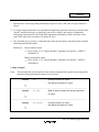
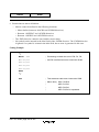
1.1.2
Coding of Source Statements
Source statements are written using ASCII characters. Character strings and comments can include
Japanese kana and kanji characters (shift JIS code or EUC code).
In principle, a single statement must be written on a single line. The maximum length of a line is
255 bytes.
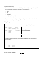
(1) Coding of Label
The label is written as follows:
• Written starting in the first column,
Or:
• Written with a colon (:) appended to the end of the label.
Examples:
; This label is written starting in the first column.
LABEL1
; This label is terminated with a colon.
LABEL2:
----------------------------------------------------------------------; This label is regarded as an error by the assembler,
LABEL3
; since it is neither written starting in the first column
; nor terminated with a colon.
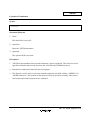
(2) Coding of Operation
The operation is written as follows:
• When there is no label:
Written starting in the second or later column.
• When there is a label:
Written after the label, separated by one or more spaces or tabs.
Examples:
LABEL1:
ADD
R0,R1
; An example with no label.
ADD
R1,R2
; An example with a label.
Rev. 4.0, 09/98, page 13 of 391
CAUTION!
Since white spaces and tabs are ASCII characters, each space or tab requires a byte of storage.
(3) Coding of Operand
The operand is written following the operation field, separated by one or more spaces or tabs.
Examples:
ADD
R0,R1
; The ADD instruction takes two operands.
SHAL
R1
; The SHAL instruction takes one operand.
(4) Coding of Comment
The comment is written following a semicolon (;).
The assembler regards all characters from the semicolon to the end of the line as the comment.
Examples:
ADD
R0,R1
Rev. 4.0, 09/98, page 14 of 391
; Adds R0 to R1.
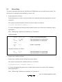
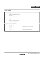
1.1.3
Coding of Source Statements across Multiple Lines
A single source statement can be written across several lines in the following situations:
• When the source statement is too long as a single statement.
• When it is desirable to attach a comment to each operand.
Write source statements across multiple lines using the following procedure.
1. Insert a new line after a comma that separates operands.
2. Insert a plus sign (+) in the first column of the new line.
3. Continue writing the source statement following the plus sign.
Spaces and tabs can be inserted following the plus sign.
Examples:
.DATA.L
H'FFFF0000,
+
H'FF00FF00,
+
H'FFFFFFFF
; In this example, a single source statement is written across three lines.
A comment can be attached at the end of each line.
Examples:
H'FFFF0000,
; Initial value 1.
+
H'FF00FF00,
; Initial value 2.
+
H'FFFFFFFF
; Initial value 3.
.DATA.L
; In this example, a comment is attached to each operand.
Rev. 4.0, 09/98, page 15 of 391
1.2
Reserved Words
Reserved words are names that the assembler reserves as symbols with special meanings.
Register names, operators, and the location counter are used as reserved words. Reserved words
are different depending on the CPU type. Refer to the programming manual of the CPU used, for
details.
Reserved words must not be used as symbols.
• Register names: R0 to R15, FR0 to FR15, DR0 to DR14 (only even values), XD0 to XD14
(only even values), FV0 to FV12 (only multiples of four), R0_BANK to R7_BANK, SP, SR,
GBR, VBR, MACH, MACL, PR, PC, SSR, SPC, FPUL, FPSCR, MOD, RE, RS, DSR, A0,
A0G, A1, A1G, M0, M1, X0, X1, Y0, Y1, XMTRX, DBR, SGR
• Operators: STARTOF, SIZEOF, HIGH, LOW, HWORD, LWORD, $EVEN, $ODD,
$EVEN2, $ODD2
• Location counter ($)
Note:
R15 and SP indicate the same register.
Reference:
Operators
→ Programmer's Guide, 1.6.1, "Expression Elements"
Location counter → Programmer's Guide, 1.5, "Location Counter"
CPU type
→ Programmer's Guide, 5.2.1, "Target CPU Assembler Directive", .CPU
→ User's Guide, 1.3, "SHCPU Environment Variable"
→ User's Guide, 2.2.1, "Target CPU Command Line Option", –CPU
Symbols
→ Programmer's Guide, 1.3, "Symbols"
1.3
Symbols
1.3.1
Functions of Symbols
Symbols are names defined by the programmer, and perform the following functions.
• Address symbols:
• Constant symbols:
Express data storage and branch destination addresses.
Express constants.
• Aliases of register names: Express general registers and floating-point registers.
Express section names. *
• Section names
Note: A section is a part of the program, and the linkage editor regards it as a unit of processing.
The following shows examples of symbol usage.
Rev. 4.0, 09/98, page 16 of 391
Examples:
∼
BRA
SUB1
∼
; BRA is a branch instruction.
; SUB1 is the address symbol of the destination.
SUB1:
∼
----------------------------------------------------------------------
∼
MAX:
.EQU
100
MOV.B #MAX,R0
∼
; EQU is an assembler directive that sets a value to a
; symbol.
; MAX expresses the constant value 100.
----------------------------------------------------------------------
∼
MIN:
.REG
MOV.B
∼
; .REG is an assembler directive that defines a register
; alias.
#100,MIN ; MIN is an alias for R0.
R0
----------------------------------------------------------------------
∼
.SECTION CD,CODE,ALIGN=4
∼
; .SECTION is an assembler directive that declares a section.
; CD is the name of the current section.
Rev. 4.0, 09/98, page 17 of 391
1.3.2
Coding of Symbols
(1) Available Characters
The following ASCII characters can be used.
• Alphabetical uppercase and lowercase letters (A to Z, a to z)
• Numbers (0 to 9)
• Underscore (_)
• Dollar sign ($)
The assembler distinguishes uppercase letters from lowercase letters in symbols.
(2) First Character in a Symbol
The first character in a symbol must be one of the following.
• Alphabetical uppercase and lowercase letters (A to Z, a to z)
• Underscore (_)
• Dollar sign ($)
CAUTION!
The dollar sign character used alone is a reserved word that expresses the location counter.
Reference:
Reserved words → Programmer's Guide, 1.2, "Reserved Words"
(3) Maximum Length of a Symbol
A symbol may contain up to 251 characters.
The assembler ignores any characters after the first 251.
(4) Names that Cannot Be Used as Symbols
Reserved words cannot be used as symbols. The following names must not be used because they
are used as internal symbols by the assembler.
_$$nnnnn (n is a number from 0 to 9.)
Note: Internal symbols are necessary for assembler internal processing. Internal symbols are not
output to assemble listings or object modules.
Rev. 4.0, 09/98, page 18 of 391
1.4
Constants
1.4.1
Integer Constants
Integer constants are expressed with a prefix that indicates the radix.
The radix indicator prefix is a notation that indicates the radix of the constant.
• Binary numbers:
• Octal numbers:
The radix indicator “B'” plus a binary constant.
The radix indicator “Q'” plus an octal constant.
The radix indicator “D'” plus a decimal constant.
• Decimal numbers:
• Hexadecimal numbers: The radix indicator “H'” plus a hexadecimal constant.
The assembler does not distinguish uppercase letters from lowercase letters in the radix indicator.
The radix indicator and the constant value must be written with no intervening space.
Examples:
.DATA.B
B'10001000
;
.DATA.B
Q'210
; These source statements express the same
.DATA.B
D'136
; numerical value.
.DATA.B
H'88
;
The radix indicator can be omitted. Integer constants with no radix indicator are normally decimal
constants, although the radix for such constants can be changed with the .RADIX assembler
directive.
Reference:
Interpretation of integer constants without a radix specified
→ Programmer's Guide, 5.2.8, "Other Assembler Directives", .RADIX
Supplement:
"Q" is used instead of "O" to avoid confusion with the digit 0.
Rev. 4.0, 09/98, page 19 of 391
1.4.2
Character Constants
Character constants are considered to be constants that represent ASCII codes.
Character constants are written by enclosing up to four ASCII characters in double quotation
marks.
The following ASCII characters can be used in character constants.
ASCII code: H'09 (tab)
H'20 (space) to H'7E (tilde)
Examples:
.DATA.L
"ABC"
; This is the same as .DATA.L H'00414243.
.DATA.W
"AB"
; This is the same as .DATA.W H'4142.
.DATA.B
"A"
; This is the same as .DATA.B H'41.
; The ASCII code for A is: H'41
; The ASCII code for B is: H'42
; The ASCII code for C is: H'43
In addition, Japanese kana and kanji characters in shift JIS code or EUC code can be used. When
using Japanese characters in shift JIS code or EUC code, be sure to specify the SJIS or EUC
command line option, respectively. Note that the shift JIS code and EUC code cannot be used
together in one source program.
Use two double quotation marks in succession to indicate a single double quotation mark in a
character constant.
Example:
.DATA.B
; This is a character constant consisting of a single
""""
double quotation mark.
.DATA.L
"
"
; Japanese kanji characters.
References:
SJIS command line option
→ User's Guide, 2.2.7, "Japanese Character Command Line Options," –SJIS
Rev. 4.0, 09/98, page 20 of 391
EUC command line option
→ User's Guide, 2.2.7, "Japanese Character Command Line Options," –EUC
1.4.3
Floating-Point Constants
Floating-point constants can be specified as operands in assembler directives for reserving
floating-point constants.
Floating-Point Constant Representation:
Floating-point constants can be represented in decimal and hexadecimal.
• Decimal representation
F'[{±}] n[.[m]]
. m
F' :
[t[[{±}]xx]]
Indicates that the number is decimal. It cannot be omitted.
[{±}] n[.[m]]
. m
: "n" indicates the integer part in decimal. "m" indicates the fraction part
in decimal. Either the integer part or the fraction part can be omitted. If the sign (±)
is omitted, the assembler assumes it is positive.
t :
Indicates that the number is in either of the following precisions
• S: Single precision
• D: Double precision
If omitted, the assembler assumes the operation size of the assembler directive.
[{±}]xx : Indicates the exponent part in decimal. If omitted, the assembler assumes 0. If the
sign (±) is omitted, the assembler assumes it is positive.
Example:
F'0.5S–2 = 0.5×10⁻²
F'.123D3 =
0.123×103
=
0.005 = H'3BA3D70A
= 123
= H'405EC00000000000
Rev. 4.0, 09/98, page 21 of 391
• Hexadecimal representation
H'xxxx[.t]
H' :
Indicates that the number is hexadecimal. It cannot be omitted.
xxxx :
Indicates the bit pattern of the floating-point constant in hexadecimal. If the bit
pattern is shorter than the specified data length, it is aligned to the right end of the
reserved area and 0s are added to the remaining bits in the reserved area. If the bit
pattern is longer than the specified data length, the right-side bits of the bit pattern are
allocated for the specified data length and the remaining bits of the bit pattern are
ignored.
t:
Indicates that the number is in either of the following precisions
• S: Single precision
• D: Double precision
If omitted, the assembler assumes the operation size of the assembler directive.
This format directly specifies the bit pattern of the floating-point constant to represent data that
is difficult to represent in decimal format, such as 0s for the specified data length or infinity.
Example:
H'0123456789ABCDEF.S
= H'89ABCDEF
H'FFFF.D
= H'000000000000FFFF
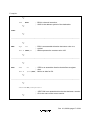
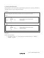
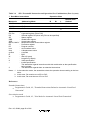
Floating-Point Data Range:
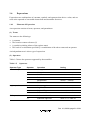
Table 1-1 lists the floating-point data types.
Table 1-1
Floating-Point Data Types
Data Type
Description
Normalized number
The absolute value is between the underflow and overflow boundaries
including the boundary values.
Denormalized number
The absolute value is between 0 and the underflow boundary.
Zero
The absolute value is 0.
Infinity
The absolute value is larger than the overflow boundary.
Not-a-Number (NAN)
A value that is not a numerical value. Includes sNAN (signaling NAN)
and qNAN (quiet NAN).
Rev. 4.0, 09/98, page 22 of 391
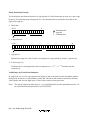
These data types are shown on the following number line. NAN cannot be shown on the number
line because it is not handled as a numerical value.
0
−∞
+∞
Negative normalized number
x
x Zero x
x
Negative denormalized number
Positive normalized number
Positive denormalized number
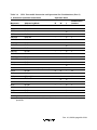
Table 1-2 lists the numerical value ranges the assembler can use.
Table 1-2
Data Types and Numerical Value Ranges (Absolute Value)
Data Type
Single Precision
Double Precision
Normalized number
Maximum value
3.40 ×
1.79 × 10308
Minimum value
1.18 × 10–38
2.23 × 10–308
Maximum value
1.17 × 10–38
2.22 × 10–308
Minimum value
1.40 ×
4.94 × 10–324
Denormalized number
1038
10–45
Floating-Point Data Format:
The floating-point data format is shown below:
Single Precision:
31,30,.......,23,22,.........................................................,0
S
E
F
Double Precision:
63,62,................,52,51,......................................................................,0
S
E
F
: Decimal point
S : Sign bit
E : Exponent part
F : Fraction part
Rev. 4.0, 09/98, page 23 of 391
• Sign bit (S)
Indicates the sign of a value. Positive and negative are represented by 0 and 1, respectively.
• Exponent part (E)
Indicates the exponent of a value. The actual exponent value is obtained by subtracting the bias
value from the value specified in this exponent part.
• Fraction part (F)
Each bit has its own significance and corresponds to 2–1, 2–2, ..., 2–n from the start bit,
respectively ("n" is the bit length of the fraction part).
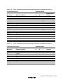
Table 1-3 shows the size of each parameter in data format.
Table 1-3
Data Format Size
Parameter
Single Precision
Double Precision
Bit length
32 bits
64 bits
Sign bit (S)
1 bit
1 bit
Exponent part (E)
8 bits
11 bits
Fraction part (F)
23 bits
52 bits
Bias of exponent value
127
1023
A floating-point number is represented using the symbols in table 1-3 as follows:
2E−bias . ( 1)s .
(1. F)
(0. F)
: Normalized number
: Denormalized number
(1. F) = 1 + b0 × 2–1 + b1 × 2–2 + ..... + bn–1 × 2–n
(0. F) = b0 × 2–1 + b1 × 2–2 + ..... + bn–1 × 2–n
b: Bit location in the fraction part
n: Bit length of the fraction part
Rev. 4.0, 09/98, page 24 of 391
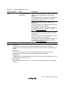
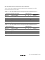
Table 1-4 shows the floating-point representation for each data type. NAN cannot be represented
because it is not handled as a numerical value.
Table 1-4
Floating-Point Representation for Each Data Type
Data Type
Single Precision
Double Precision
Normalized number
(–1)s · 2E–127 · (1. F)
(–1)s · 2E–1023 · (1. F)
Denormalized number
(–1)s
(–1)s · 2–1022 · (0. F)
Zero
(–1)s · 0
(–1)s · 0
Infinity
(–1)s · ∞
(–1)s · ∞
Not-a-Number (NAN)
quiet NAN, signaling NAN
quiet NAN, signaling NAN
·
2–126
· (0. F)
Valid Range for Floating-Point Constants:
When converting floating-point constants used in assembler directives for reserving floating-point
numbers into object codes, the assembler rounds them in the following two modes to set the valid
range.
• Round to Nearest even (RN)
Rounds the least significant bit in the object code to its nearest absolute value. When two
absolute values are at the same distance, rounds the least significant bit to become zero.
• Round to Zero (RZ)
Rounds the least significant bit in the object code to zero.
Example:
Object code of .FDATA.S F' 1S-1
RN: H'3DCCCCCD
RZ: H'3DCCCCCC
Reference:
Rounding mode setting
→ User's Guide, 2.2.10, "Floating-Point Data Command Line Options," –ROUND
Rev. 4.0, 09/98, page 25 of 391
Handling Denormalized Numbers:
The assembler handles denormalized numbers differently depending on the CPU type. In a CPU
that does not handle denormalized numbers, if a value in the denormalized number range is used,
warning number 841 occurs and the object code is output as zero.
In a CPU that handles denormalized numbers, if a value in the denormalized number range is used,
warning number 842 occurs and the object code is output in denormalized numbers.
How to handle denormalized numbers can be switched with the DENORMALIZE command line
option.
Examples:
CPU not handling denormalized numbers:
.FDATA.S F' 1S-40
Warning 841, Object code H'00000000
CPU handling denormalized numbers:
.FDATA.S F' 1S-40
Warning 842, Object code H'000116C2
Reference:
Denormalized numbers
→ User's Guide, 2.2.10, "Floating-Point Data Command Line Options," –DENORMALIZE
1.4.4
Fixed-Point Constants
Fixed-point constants can be specified as operands in the assembler directive for reserving fixedpoint data.
Fixed-Point Number Representation:
Fixed-point numbers express real numbers ranging from –1.0 to 1.0 in decimal.
Word size and longword size are available for fixed-point numbers.
• Word-size fixed-point numbers
Two-byte signed integers expressing real numbers ranging from –1.0 to 1.0.
The real number expressed by 2-byte signed integer x (–32,768 < = x < = 32,767) is x/32768.
Rev. 4.0, 09/98, page 26 of 391
Example:
Fixed-point number
Word-size representation
–1.0
H'8000
–0.5
H'C000
0.0
H'0000
0.5
H'4000
1.0
H'7FFF
• Longword-size fixed-point numbers
Four-byte signed integers expressing real numbers ranging from –1.0 to 1.0. The real number
expressed by 4-byte signed integer x (–2,147,483,648 < = x < = 2,147,483,647) is
x/2147483648.
Example:
Fixed-point number
Longword-size representation
–1.0
H'80000000
–0.5
H'C0000000
0.0
H'00000000
0.5
H'40000000
1.0
H'7FFFFFFF
Rev. 4.0, 09/98, page 27 of 391
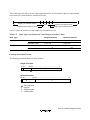
Fixed-Point Data Format:
The fixed-point data format consists of a sign bit and a 15-bit fraction part in word size, and a sign
bit and a 31-bit fraction part in longword size. The decimal point is assumed to be fixed on the
right of the sign bit.
• Word size
1514
S
0
: Decimal point
S : Sign bit
F : Fraction part
F
• Longword size
3130
S
0
F
• Sign bit (S)
Indicates the sign of a value. Positive and negative are represented by 0 and 1, respectively.
• Fraction part (F)
Each bit has its own significance and corresponds to 2–1, 2–2, ..., 2–31 from the start bit,
respectively.
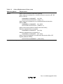
Valid Range for Fixed-Point Numbers:
In long-word size, 31 bits can represent nine digits of data in decimal, but the assembler handles
ten digits in decimal as a valid number, rounds the 35th bit in RN (round to the nearest absolute
value) mode, and uses the high-order 31 bits of the result as fixed-point data.
Note: The actual fixed-point data range is –1.0 to 0.9999999999, but the assembler assumes 1.0
as 0.9999999999 and represents it as H'7FFFFFFF.
Rev. 4.0, 09/98, page 28 of 391
1.5
Location Counter
The location counter expresses the address (location) in memory where the corresponding object
code (the result of converting executable instructions and data into code the microprocessor can
regard) is stored.
The value of the location counter is automatically adjusted according to the object code output.
The value of the location counter can be changed intentionally using assembler directives.
Examples:
∼
.ORG
H'00001000
; This assembler directive sets the location counter to
; H'00001000.
.DATA.W
H'FF
; The object code generated by this assembler directive has
; a length of 2 bytes.
; The location counter changes to H'00001002.
.DATA.W
H'F0
; The object code generated by this assembler directive has
; a length of 2 bytes.
; The location counter changes to H'00001004.
.DATA.W
H'10
; The object code generated by this assembler directive has
; a length of 2 bytes.
; The location counter changes to H'00001006.
.ALIGN
4
; The value of the location counter is corrected to be a multiple
; of 4.
; The location counter changes to H'00001008.
.DATA.L
H'FFFFFFFF
; The object code generated by this assembler directive has
; a length of 4 bytes.
; The location counter changes to H'0000100C.
;
;
;
;
;
∼
.ORG is an assembler directive that sets the value of the location counter.
.ALIGN is an assembler directive that adjusts the value of the location counter.
.DATA is an assembler directive that reserves data in memory.
.W is a specifier that indicates that data is handled in word (2 bytes) size.
.L is a specifier that indicates that data is handled in longword (4 bytes) size.
Rev. 4.0, 09/98, page 29 of 391
References:
Setting the value of the location counter
→ Programmer's Guide, 5.2.2, "Section and Location Counter Assembler Directives", .ORG
Correcting the value of the location counter
→ Programmer's Guide, 5.2.2, "Section and Location Counter Assembler Directives",
.ALIGN
The location counter is referenced using the dollar sign symbol.
Examples:
LABEL1:
.EQU
$
; This assembler directive sets the value of the
; location counter to the symbol LABEL1.
;
.EQU is an assembler directive that sets the value to a symbol.
Rev. 4.0, 09/98, page 30 of 391
1.6
Expressions
Expressions are combinations of constants, symbols, and operators that derive a value, and are
used as the operands of executable instructions and assembler directives.
1.6.1
Elements of Expression
An expression consists of terms, operators, and parentheses.
(1) Terms
The terms are the followings:
• A constant
• The location counter reference ($)
• A symbol (excluding aliases of the register name)
• The result of a calculation specified by a combination of the above terms and an operator.
An independent term is also a type of expression.
(2) Operators
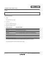
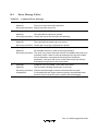
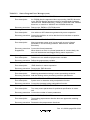
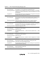
Table 1-5 shows the operators supported by the assembler.
Table 1-5
Operators
Operator Type
Operator
Operation
Coding
Arithmetic operations
+
Unary plus
+ <term>
–
Unary minus
– <term>
+
Addition
<term1> + <term2>
–
Subtraction
<term1> – <term2>
*
Multiplication
<term1> * <term2>
/
Division
<term1> / <term2>
~ ^
Unary negation
~ <term>
&
Logical AND
<term1> & <term2>
|
Logical OR
<term1> | <term2>
~ ^
Exclusive OR
<term1> ~ <term2>
<<
Arithmetic left shift
<term 1> << <term 2>
>>
Arithmetic right shift
<term 1> >> <term 2>
Logic operations
Shift operations
Rev. 4.0, 09/98, page 31 of 391
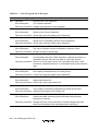
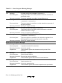
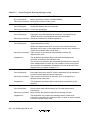
Table 1-5
Operators (cont)
Operator Type
Operator
Operation
Coding
Section set
operations*
STARTOF
Derives the starting address
of a section set.
STARTOF <section name>
SIZEOF
Derives the size of a section
set in bytes.
SIZEOF <section name>
$EVEN
1 when the value is a
multiple of 2, and 0
otherwise
$EVEN <symbol>
$ODD
0 when the value is a
multiple of 2, and 1
otherwise
$ODD <symbol>
$EVEN2
1 when the value is a
multiple of 4, and 0
otherwise
$EVEN2 <symbol>
$ODD2
0 when the value is a
multiple of 4, and 1
otherwise
$ODD2 <symbol>
Even/odd operations
Extraction operations
HIGH
Extracts the high-order byte
HIGH <term>
LOW
Extracts the low-order byte
LOW <term>
HWORD
Extracts the high-order word
HWORD <term>
LWORD
Extracts the low-order word
LWORD <term>
Note: See the supplement below.
Supplement:
In this assembly language, programs are divided into units called section. Sections are the units in
which linkage processing is performed.
When there are multiple sections of the same type and same name within a given program, the
linkage editor links them into a single "section set".
Reference:
Sections → Programmer's Guide, 2.1, "Sections"
(3) Parentheses
Parentheses modify the operation precedence.
See the next section, section 1.6.2, "Operation Precedence", for a description of the use of
parentheses.
Rev. 4.0, 09/98, page 32 of 391
1.6.2
Operation Precedence
When multiple operations appear in a single expression, the order in which the processing is
performed is determined by the operator precedence and by the use of parentheses. The assembler
processes operations according to the following rules.
<Rule 1>
Processing starts from operations enclosed in parentheses.
When there are multiple parentheses, processing starts with the operations surrounded by the
innermost parentheses.
<Rule 2>
Processing starts with the operator with the highest precedence.
<Rule 3>
Processing proceeds in the direction of the operator association rule when operators have the same
precedence.
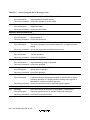
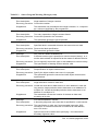
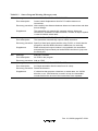
Table 1-6 shows the operator precedence and the association rule.
Table 1-6
Operator Precedence and Association Rules
Precedence
Operator
Association Rule
1 (high)
+ – ~ ^ STARTOF SIZEOF
$EVEN $ODD $EVEN2 $ODD2
HIGH LOW HWORD LWORD*
Operators are processed from right to left.
2
* /
Operators are processed from left to right.
3
+ –
Operators are processed from left to right.
4
<< >>
Operators are processed from left to right.
5
&
Operators are processed from left to right.
6 (low)
| ~ ^
Operators are processed from left to right.
Note: The operators of precedence 1 (highest precedence) are for unary operation.
Rev. 4.0, 09/98, page 33 of 391
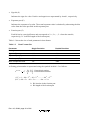
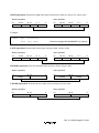
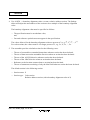
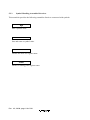
The figures below show examples of expressions.
Example 1:
1 + ( 2 - ( 3 + ( 4 - 5 ) ) )
(a)
(b)
(c)
(d)
The assembler calculates this expression in the order (a) to (d).
The result of (a) is –1
The result of (b) is 2
The result of (c) is 0
The result of (d) is 1
The final result of this calculation is 1.
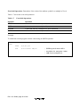
Example 2:
- H'FFFFFFF1 + H'000000F0 * H'00000010 | H'000000F0 & H'0000FFFF
(a)
(b)
(d)
(c)
(e)
The assembler calculates this expression in the order (a) to (e).
The result of (a) is H'0000000F
The result of (b) is H'00000F00
The result of (c) is H'00000F0F
The result of (d) is H'000000F0
The result of (e) is H'00000FFF
Rev. 4.0, 09/98, page 34 of 391
The final result of this calculation is H'00000FFF.
Example 3:
- ~ - ~ H'0000000F
(a)
(b)
(c)
(d)
The assembler calculates this expression in the order (a) to (d).
The result of (a) is H'FFFFFFF0
The result of (b) is H'00000010
The result of (c) is H'FFFFFFEF
The result of (d) is H'00000011
The final result of this calculation is H'00000011.
Rev. 4.0, 09/98, page 35 of 391
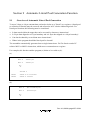
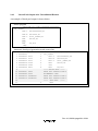
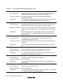
1.6.3
Detailed Description on Operation
STARTOF Operation: Determines the start address of a section set after the specified sections
are linked by the linkage editor.
SIZEOF Operation: Determines the size of a section set after the specified section are linked by
the linkage editor.
Example:
.CPU
SH1
.SECTION INIT_RAM,DATA,ALIGN=4
.RES.B
H'100
.SECTION INIT_DATA,DATA,ALIGN=4
INIT_BGN .DATA.L
(STARTOF INIT_RAM).......................; (1)
INIT_END .DATA.L
(STARTOF INIT_RAM) + (SIZEOF INIT_RAM)...; (2)
;
;
.SECTION MAIN,CODE,ALIGN=4
INITIAL:
MOV.L
DATA1,R6
MOV
#0,R5
MOV.L
DATA1+4,R3
BRA
LOOP2
MOV.L
@R3,R4
LOOP1:
Initializes the data area in section
MOV.L
R5,@R4
INIT_RAM to 0.
ADD
#4,R4
LOOP2:
MOV.L
@R6,R3
CMP/HI
R3,R4
BF
LOOP1
RTS
NOP
DATA1:
.DATA.L
INIT_END
.DATA.L
INIT_BGN
.END
(1) Determines the start address of section INIT_RAM.
(2) Determines the end address of section INIT_RAM.
Rev. 4.0, 09/98, page 36 of 391
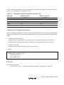
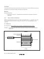
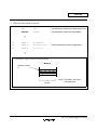
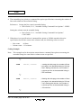
HIGH Operation: Extracts the high-order byte from the low-order two bytes of a 4-byte value.
Before operation
31
24 23
After operation
16 15
8 7
0
31
H'xx
H'00
24 23
16 15
8 7
0
H'00
H'00
H'xx
Example:
LABEL
.EQU
H'00007FFF
.DATA
HIGH LABEL
; Reserves integer data H'0000007F on memory.
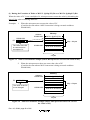
LOW Operation: Extracts the lowest-order one byte from a 4-byte value.
Before operation
31
24 23
After operation
16 15
8 7
0
31
H'xx
H'00
24 23
16 15
8 7
0
H'00
H'00
H'xx
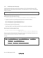
HWORD Operation: Extracts the high-order two bytes from a 4-byte value.
Before operation
31
After operation
16 15
0
31
H'xxxx
16 15
H'0000
0
H'xxxx
LWORD Operation: Extracts the low-order two bytes from a 4-byte value.
Before operation
31
After operation
16 15
0
H'xxxx
31
16 15
H'0000
0
H'xxxx
Rev. 4.0, 09/98, page 37 of 391
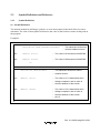
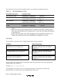
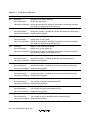
Even/Odd Operation: Determines if the value of the address symbol is a multiple of 2 or 4.
Table 1-7 shows the even/odd operations.
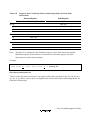
Table 1-7
Even/Odd Operations
Operator
Operation
$EVEN
1 when the value is a multiple of 2, and 0 otherwise
$ODD
0 when the value is a multiple of 2, and 1 otherwise
$EVEN2
1 when the value is a multiple of 4, and 0 otherwise
$ODD2
0 when the value is a multiple of 4, and 1 otherwise
Example:
To obtain the current program counter value using an $ODD2 operator.
LAB:
MOVA
@(0,PC),R0
ADD
#-4+2*$ODD2 LAB,R0
; $ODD2 gives 0 when LAB is
; a multiple of 4, and gives 1 when
; LAB is not a multiple of 4.
Rev. 4.0, 09/98, page 38 of 391
1.6.4
Notes on Expressions
(1) Internal Processing
The assembler regards expression values as 32-bit signed values.
Example:
~H'F0
The assembler regards H'F0 as H'000000F0.
Therefore, the value of ~H'F0 is H'FFFFFF0F. (Note that this is not H'0000000F.)
(2) Arithmetic Operators
Where values must be determined at assembly, the multiplication and division operators cannot
take terms that contain relative values (values which are not determined until the end of the
linkage process) as their operands.
Example:
.IMPORT
SYM
.DATA
SYM/10
; Correctly assembled.
.ORG
SYM/10
; An error will occur.
Also, a divisor of 0 cannot be used with the division operator.
(3) Logic Operators
The logic operators cannot take terms that contain relative values as their operands.
Reference:
Relative values → Programmer's Guide, 2.2, "Absolute and Relative Values".
Rev. 4.0, 09/98, page 39 of 391
1.7
Character Strings
Character strings are sequences of character data.
The following ASCII characters can be used in character strings.
ASCII code: H'09 (tab)
H'20 (space) to H'7E (tilde)
A single character in a character string has as its value the ASCII code for that character and is
represented as a byte sized data object. In addition, Japanese kana and kanji characters in shift JIS
code or EUC code can be used. When using Japanese characters in shift JIS code or EUC code, be
sure to specify the SJIS or EUC command line option, respectively. If not specified, Japanese
characters are handled as the Japanese code specified by the host machine.
Character strings must be written enclosed in double quotation marks.
Use two double quotation marks in succession to indicate a single double quotation mark in a
character string.
Examples:
.SDATA
; This statement reserves the character string data
"Hello!"
; Hello!
.SDATA
"
"
; This statement reserves the character string data
;
.SDATA
"""Hello!"""
; This statement reserves the character string data
; "Hello!"
;
.SDATA is an assembler directive that reserves character string data in memory.
Supplement:
The difference between character constants and character strings is as follows.
Character constants are numeric values. They have a data size of either 1 byte, 2 bytes, or 4 bytes.
Character strings cannot be handled as numeric values. A character string has a data size between
1 byte and 255 bytes.
Rev. 4.0, 09/98, page 40 of 391
References:
SJIS command line option
→ User's Guide, 2.2.7, "Japanese Character Command Line Options," –SJIS
EUC command line option
→ User's Guide, 2.2.7, "Japanese Character Command Line Options," –EUC
Rev. 4.0, 09/98, page 41 of 391
1.8
Local Label
1.8.1
Local Label Functions
A local label is valid locally between address symbols. Since a local label does not conflict with
the other labels outside its scope, the user does not have to consider other label names. A local
label can be defined by writing in the label field in the same way as a normal address symbol, and
can be referenced by an operand.
An example of local label descriptions is shown below.
Example:
LABEL1:
?0001:
; Local block 1 start
∼
CMP/EQ
BT
BRA
?0002:
LABEL2:
?0001:
R1,R2
?0002
?0001
∼
∼
CMP/GE
BT
BRA
; Branches to ?0002 of local block 1
; Branches to ?0001 of local block 1
; Local block 2 start
R1,R2
?0002
?0001
?0002:
LABEL3:
; Branches to ?0002 of local block 2
; Branches to ?0001 of local block 2
; Local block 3 start
Note:
A local label cannot be referenced during debugging.
A local label cannot be specified as any of the following items:
• Macro name
• Section name
• Object module name
• Label in .ASSIGNA, .ASSIGNC, .EQU, .ASSIGN, .REG, or .DEFINE
• Operand in .EXPORT, .IMPORT, or .GLOBAL
Rev. 4.0, 09/98, page 42 of 391
1.8.2
Description Method of Local Label
First Character:
A local label is a character string starting with a question mark (?).
Usable Characters:
The following ASCII characters can be used in a local label, except for the first character:
• Alphabetical uppercase and lowercase letters (A to Z and a to z)
• Numbers (0 to 9)
• Underscore (_)
• Dollar sign ($)
The assembler distinguishes uppercase letters from lowercase ones in local labels.
Maximum Length:
The length of local label characters is 2 to 16 characters. If 17 or more characters are specified, the
assembler will not recognize them as a local label.
1.8.3
Scope of Local Labels
The scope of a local label is called a local block. Local blocks are separated by address symbols,
or by the .SECTION directives.
The local label defined within a local block can be referenced in that local block.
A local label belonging to a local block is interpreted as being unique even if its spelling is the
same as local labels in other local blocks; it does not cause an error.
Note:
The address symbols defined by the .EQU or .ASSIGN directive are not interpreted as delimiters
for the local block.
Rev. 4.0, 09/98, page 43 of 391
Section 2 Basic Programming Knowledge
2.1
Sections
If source programs are compared to natural language writing, a section will correspond to a
"chapter." The section is the processing unit used when the linkage editor links object modules.
2.1.1
Section Types by Usage
Sections are classified by usage into the following types.
• Code section
• Data section
• Common section
• Stack section
• Dummy section
(1) Code Section
The following can be written in a code section:
• Executable instructions
• Extended instructions
• Assembler directives that reserve initialized data.
Examples:
.SECTION
CD,CODE,ALIGN=4
; This assembler directive declares a
; code section with the name CD.
MOV.L
X,R1
∼
R1,R2
MOV
X:
.ALIGN
4
.DATA.L
H'FFFFFFFF
∼
; This is an executable instruction.
; This assembler directive reserves
; initialized data.
Rev. 4.0, 09/98, page 45 of 391
(2) Data Section
The following can be written in a data section:
• Assembler directives that reserve initialized data.
• Assembler directives that reserve uninitialized data.
Examples:
.SECTION
DT1,DATA,ALIGN=4
; This assembler directive declares
; a data section with the name DT1.
.DATA.W
H'FF00
; These assembler directives reserve
.DATA.B
H'FF
; initialized data.
~
.SECTION
DT2,DATA,ALIGN=4
; This assembler directive declares
; a data section with the name DT2.
.RES.W
10
; These assembler directives reserve
.RES.B
10
; data areas that do not have initial
; values.
~
Rev. 4.0, 09/98, page 46 of 391
(3) Common Section
A common section is used as a section to hold data that is shared between files when a source
program consists of multiple source files.
The following can be written in a common section:
• Assembler directives that reserve initialized data.
• Assembler directives that reserve uninitialized data.
Supplement:
The linkage editor reserves common sections with the same name to the same area in memory. In
the example shown in figure 2-1, the common section CM declared in file A and the common
section CM declared in file B are reserved to the same area in memory.
Memory
Program
File A
File B
Common section CM
Common section CM
Common section CM
Figure 2-1 Memory Reservation of Common Section
Rev. 4.0, 09/98, page 47 of 391
(4) Stack Section
The section that the microprocessor uses as a stack area (an area for temporary data storage) is
called the stack section.
The following can be written in the stack section:
• Assembler directives that reserve uninitialized data.
Examples:
.SECTION ST,STACK,ALIGN=4
; This assembler directive declares a
; stack section with the name ST.
.RES.B
1024
; This assembler directive reserves a
; stack area of 1024 bytes.
STK:
(5) Dummy Section
A dummy section is a hypothetical section for representing data structures. The assembler does not
output dummy sections to the object module.
The following can be written in a dummy section:
• Assembler directives that reserve uninitialized data.
Examples:
.SECTION DM,DUMMY
; This assembler directive declares
; a dummy section with the name DM.
.RES.B
1
; The assembler does not output the
A:
.RES.B
1
; section DM to the object module.
B:
.RES.B
2
∼
Specific methods for specifying data structures are described in the supplement on the next page.
Rev. 4.0, 09/98, page 48 of 391
Supplement:
As shown in figure 2-2, it is possible to access areas in memory by using address symbols from a
dummy section.
Data structure
Memory
Reference
point
The start of
area 1
Address
symbol A
Item A
Address
symbol B
Item B
Dummy
section
The start of area 1
plus A
The start of area 1
plus B
Item A
Area 1
Item B
The start of
area 2
The start of area 2
plus A
The start of area 2
plus B
Item A
Area 2
Item B
Figure 2-2 Data Structure Example Using Dummy Section
Example:
In the example above, assume that R1 holds the starting address of area 1 and R2 holds the
starting address of area 2.
MOV.L
@(B,R1),R0
; Moves the contents of item B in area 1 to R0.
MOV.L
R0,@(B,R2)
; Moves the contents of R0 to item B in area 2.
∼
Rev. 4.0, 09/98, page 49 of 391
CAUTION!
1. The following cannot be used in stack and dummy sections:
a. Executable instructions
b. Extended instructions
c. Assembler directives that reserve initialized data
(.DATA, .DATAB, .SDATA, .SDATAB, .SDATAC, .SDATAZ, .FDATA, .FDATAB, and
.XDATA)
2. When using a data or common section, be sure to keep in mind whether that section is reserved
to ROM or RAM.
2.1.2
Absolute Address Sections and Relative Address Sections
A section can be classified as either an absolute address section or as a relative address section
depending on whether absolute start addresses are given to the sections at assembly.
(1) Absolute Address Section
The memory locations of absolute address sections are specified in the source program, and cannot
be changed by the linkage editor. In this assembly language, locations in an absolute address
section are expressed as absolute addresses, which are addresses that express the actual position in
memory.
Examples:
.SECTION ABS,DATA,LOCATE=H'0000F000
; ABS is an absolute address section.
; The starting address of section ABS is
; the absolute address H'0000F000.
.DATA.W
H'1111
; The constant H'1111 is reserved at
; the absolute address H'0000F000.
.DATA.W
H'2222
; The constant H'2222 is reserved at
; the absolute address H'0000F002.
Rev. 4.0, 09/98, page 50 of 391
(2) Relative Address Section
The locations in memory of relative section are not specified in the source program, but rather are
determined when the sections are linked by the linkage editor. In this assembly language, locations
in a relative address section are expressed as relative addresses, which are addresses that express
the position relative to the start of the section itself.
Examples:
.SECTION
REL,DATA,ALIGN=4
; REL is a relative address section.
; The starting address of section REL is
; determined after linkage.
.DATA.W
H'1111
; The constant H'1111 is reserved at the
; relative address H'00000000.
.DATA.W
H'2222
; The constant H'2222 is reserved at the
; relative address H'00000002.
Supplement:
Dummy sections correspond neither to relative nor to absolute address sections.
Rev. 4.0, 09/98, page 51 of 391
2.2
Absolute and Relative Values
Absolute values are determined when assembly completes. Relative values are not determined
until the linkage editor completes.
2.2.1
Absolute Values
The following are the absolute values handled by the assembler.
(1) Constants
• Integer constants
• Character constants
• Symbols that have a value that is one of the above (hereafter referred to as constant symbols).
(2) Absolute Address Values
• The location counter referenced in an absolute address section
• The location counter referenced in a dummy section
• Symbols that have a value that is one of the above (hereafter referred to as absolute address
symbols).
(3) Other Absolute Values
Expressions whose value is determined when assembly completes.
2.2.2
Relative Values
The following are the relative values handled by the assembler.
(1) Relative Address Values
• The location counter referenced in a relative address section
• Symbols that have the above as a value (hereafter referred to as relative address symbols).
(2) External Reference Values
Symbols that reference another file (hereafter referred to as import symbols).
(3) Other Relative Values
Expressions whose value is not determined until the linkage editor completes.
Rev. 4.0, 09/98, page 52 of 391
2.3
Symbol Definition and Reference
2.3.1
Symbol Definition
(1) Normal Definition
The normal method for defining a symbol is to write that symbol in the label field of a source
statement. The value of that symbol will then be the value of the location counter at that point in
the program.
Examples:
.SECTION DT1,DATA,LOCATE=H'0000F000
; This statement declares an
; absolute address section.
X1:
.DATA.W
H'1111
; The value of X1 becomes H'0000F000.
X2:
.DATA.W
H'2222
; The value of X2 becomes H'0000F002.
~
.SECTION DT2,DATA,ALIGN=4
; This statement declares a relative
; address section.
Y1:
.DATA.W
H'1111
; The value of Y1 is determined when
; linkage completes, and its value is
; the start address of the section.
Y2:
.DATA.W
H'2222
; The value of Y2 is determined when
; linkage completes, and its value is
; the start address of the section
; plus 2.
Rev. 4.0, 09/98, page 53 of 391
(2) Definition by Assembler Directive
Symbols can be defined by using assembler directives to set an arbitrary value or a special
meaning.
Examples:
.SECTION DT1,DATA,ALIGN=4
; DT1 is the section name.
; A section name is also a type of symbol
; that expresses the start address of
; a section.
; However, the syntactic handling of address
; symbols and section names is different.
X:
.EQU
100
; The value of X is 100.
; X cannot be redefined.
Y:
.ASSIGN
10
; The value of Y is 10.
; Y can be redefined.
Z:
.REG
R1
; Z becomes an alias of the general
; register R1.
; Z cannot be redefined.
Rev. 4.0, 09/98, page 54 of 391
2.3.2
Symbol Reference
There are three forms of symbol reference as follows:
• Forward reference
• Backward reference
• External reference
Supplement:
Figure 2-3 shows the meaning of the terms forward and backward as used in this manual.
File
Backward
Source program start
Reference position
Forward
Source program end
Figure 2-3 Meaning of the Terms Forward and Backward
Figure 2-4 shows the meaning of the term external as used in this manual.
File
File
Reference position
External
Figure 2-4 Meaning of the Term External
Rev. 4.0, 09/98, page 55 of 391
(1) Forward Reference
Forward reference means referencing a symbol that is defined forward from the point of reference.
Examples:
∼
BRA
FORWARD:
FORWARD
∼
∼
; BRA is a branch instruction.
; This is a forward reference to the symbol FORWARD.
(2) Backward Reference
Backward reference means referring to a symbol that is defined backward from the point of
reference.
Examples:
BACK:
∼
∼
BRA
BACK
∼
; BRA is a branch instruction.
; This is a backward reference to the symbol BACK.
(3) External Reference
When a source program consists of multiple source files, a reference to a symbol defined in
another file is called an external reference. External reference is described in the next
section, 2.4, "Separate Assembly".
Rev. 4.0, 09/98, page 56 of 391
2.4
Separate Assembly
2.4.1
Separate Assembly
Separate assembly refers to the technique of creating a source program in multiple separate source
files, and finally creating a single load module by linking together those source files' object
modules using the linkage editor.
The process of developing software often consists of repeatedly correcting and reassembling the
program. In such cases, if the source program is partitioned, it will be only necessary to
reassemble the source file that was changed. As a result, the time required to construct the
complete program will be significantly reduced.
If a source program is collected
together in a single file...
File
Processing 1
If a source program is partitioned
into several files...
File
Processing 1
File
Processing 2
Processing 2
Processing 3
File
Processing 3
File
Processing 4
Processing 4
File
Processing 5
Processing 5
File
Processing 6
Processing 6
: Part of the source program that
requires changes.
: Range of the program that must
be reassembled.
Figure 2-5 Relationship between the Changed Range of the Source Program and the Range
of the Program that must be Reassembled
Rev. 4.0, 09/98, page 57 of 391
The procedure involved in separate assembly consists of steps 1 to 4.
1. Investigate methods for partitioning the program.
Normally, programs are partitioned by function.
Note that the memory reservation of the section must also be considered at this point.
2. Divide the source program into separate files and edit those files accordingly.
3. Assemble the individual files.
4. Link the individual object modules into a single load module.
2.4.2
Declaration of Export Symbols and Import Symbols
When a source program consists of multiple files, referencing a symbol defined in one file from
another file is called "external reference" or "import." When referencing a symbol externally, it is
necessary to declare to the assembler that "this symbol is shared between multiple files" (this
declaration is called "external definition" or "export").
(1) Export Symbol Declaration
This declaration is used to declare that the definition of the symbol is valid in other files.
.EXPORT or .GLOBAL directive is used to make this declaration.
Rev. 4.0, 09/98, page 58 of 391
(2) Import Symbol Declaration
This declaration is used to declare that a symbol defined in another file is referenced. .IMPORT or
.GLOBAL directive is used to make this declaration.
Examples:
In this example the symbol MAX is defined in file A and referenced in file B.
File A:
MAX:
File B:
∼
.EXPORT
MAX
; Declares MAX to be an export symbol.
∼
100
; Defines MAX.
MAX
; Declares MAX to be an import symbol.
#MAX,R0
; References MAX.
.EQU
∼
.IMPORT
∼
MOV
Reference:
Symbol Export and Import
→ Programmer's Guide, 5.2.5, "Export and Import Assembler Directives", .EXPORT,
.IMPORT, .GLOBAL
Rev. 4.0, 09/98, page 59 of 391
Section 3 Executable Instructions
3.1
Overview of Executable Instructions
The executable instructions are the instructions of microprocessor. The microprocessor interprets
and executes the executable instructions in the object code stored in memory.
An executable instruction source statement has the following basic form.
[<symbol>:]
<mnemonic>[.<operation size>] [ <addressing mode>[,<addressing mode]] [;<comment>]
Label
Operation
Comment
Operand
This section describes the mnemonic, operation size, and addressing mode. The other elements are
described in detail in section 1, "Program Elements", in the Programmer's Guide.
(1) Mnemonic
The mnemonic expresses the executable instruction. Abbreviations that indicate the type of
processing are provided as mnemonics for microprocessor instructions.
The assembler does not distinguish uppercase and lowercase letters in mnemonics.
(2) Operation Size
The operation size is the unit for processing data. The operation sizes vary with the executable
instruction. The assembler does not distinguish uppercase and lowercase letters in the operation
size.
Specifier
Data Size
B
Byte
W
Word (2 bytes)
L
Longword (4 bytes)
S
Single precision (4 bytes)
D
Double precision (8 bytes)
Rev. 4.0, 09/98, page 61 of 391
(3) Addressing Mode
The addressing mode specifies the data area accessed, and the destination address. The addressing
modes vary with the executable instruction. Table 3-1 shows the addressing modes.
Table 3-1
Addressing Modes
Addressing Mode
Name
Description
Rn
Register direct
The contents of the specified register.
@Rn
Register indirect
A memory location. The value in Rn gives the start
address of the memory accessed.
@Rn+
Register indirect with
post-increment
A memory location. The value in Rn (before being
incremented*1) gives the start address of the
memory accessed.
The microprocessor first uses the value in Rn for
the memory reference, and increments Rn
afterwards.
@–Rn
Register indirect with
pre-decrement
A memory location. The value in Rn (after being
decremented*2) gives the start address of the
memory accessed.
The microprocessor first decrements Rn, and then
uses that value for the memory reference.
@(disp,Rn)
Register indirect with
displacement*3
A memory location. The start address of the
memory access is given by: the value of Rn plus
the displacement (disp).
The value of Rn is not changed.
@(R0,Rn)
Register indirect with
index
A memory location. The start address of the
memory access is given by: the value of R0 plus
the value of Rn.
The values of R0 and Rn are not changed.
@(disp,GBR)
GBR indirect with
displacement
A memory location. The start address of the
memory access is given by: the value of GBR plus
the displacement (disp).
The value of GBR is not changed.
@(R0,GBR)
GBR indirect with index A memory location. The start address of the
memory access is given by: the value of GBR plus
the value of R0.
The values of GBR and R0 are not changed.
@(disp,PC)
PC relative with
displacement
Notes 1 to 3: See next page.
Rev. 4.0, 09/98, page 62 of 391
A memory location. The start address of the
memory access is given by: the value of the PC
plus the displacement (disp).
Table 3-1
Addressing Modes (cont)
Addressing Mode
Name
Description
symbol
PC relative specified
with symbol
[When used as the operand of a branch instruction]
The symbol directly indicates the destination
address.
The assembler derives a displacement (disp) from
the symbol and the value of the PC, using the
formula: disp = symbol – PC.
[When used as the operand of a data move
instruction]
A memory location. The symbol indicates the start
address of the memory accessed.
The assembler derives a displacement (disp) from
the symbol and the value of the PC, using the
formula: disp = symbol – PC.
[When used as the operand of an instruction that
specifies the RS or RE register (LDRS or LDRE
instruction)]
A memory location. The symbol indicates the start
address*4 of the memory accessed.
The assembler derives a displacement (disp) from
the symbol and the value of the PC, using the
formula: disp = symbol – PC.
#imm
Immediate
Indicates a constant.
Notes: 1. Increment
The amount of the increment is 1 when the operation size is a byte, 2 when the
operation size is a word (two bytes), and 4 when the operation size is a longword (four
bytes).
2. Decrement
The amount of the decrement is 1 when the operation size is a byte, 2 when the
operation size is a word, and 4 when the operation size is a longword.
3. Displacement
A displacement is the distance between two points. In this assembly language, the unit
of displacement values is in bytes.
4. Start address
Refer to Programmer's Guide, 10.1, "Overview of Automatic Repeat Loop Generation
Function."
Rev. 4.0, 09/98, page 63 of 391
The values that can be used for the displacement vary with the addressing mode and the operation
size.
Table 3-2
Allowed Displacement Values
Addressing Mode
Displacement*
@(disp,Rn)
When the operation size is byte (B):
H'00000000 to H'0000000F (0 to 15)
When the operation size is word (W):
H'00000000 to H'0000001E (0 to 30)
When the operation size is longword (L):
H'00000000 to H'0000003C (0 to 60)
@(disp,GBR)
When the operation size is byte (B):
H'00000000 to H'000000FF (0 to 255)
When the operation size is word (W):
H'00000000 to H'000001FE (0 to 510)
When the operation size is longword (L):
H'00000000 to H'000003FC (0 to 1020)
@(disp,PC)
[When used as an operand of a move instruction]
When the operation size is word (W):
H'00000000 to H'000001FE (0 to 510)
When the operation size is longword (L):
H'00000000 to H'000003FC (0 to 1020)
[When used as an operand of an instruction that sets the RS or RE
register (LDRS or LDRE)]
H'FFFFFF00 to H'000000FE (–256 to 254)
Note: Units are bytes, and numbers in parentheses are decimal.
Rev. 4.0, 09/98, page 64 of 391
Table 3-2
Allowed Displacement Values (cont)
Addressing Mode
Displacement*
symbol
[When used as a branch instruction operand]
When used as an operand for a conditional branch instruction (BT, BF,
BF/S, or BT/S):
H'00000000 to H'000000FF (0 to 255)
H'FFFFFF00 to H'FFFFFFFF (–256 to –1)
When used as an operand for an unconditional branch instruction
(BRA or BSR)
H'00000000 to H'00000FFF (0 to 4095)
H'FFFFF000 to H'FFFFFFFF (–4096 to –1)
[When used as the operand of a data move instruction]
When the operation size is word (W):
H'00000000 to H'000001FE (0 to 510)
When the operation size is longword (L):
H'00000000 to H'000003FC (0 to 1020)
[When used as an operand of an instruction that sets the RS or RE
register (LDRS or LDRE)]
H'FFFFFF00 to H'000000FE (–256 to 254)
Note: Units are bytes, and numbers in parentheses are decimal.
Rev. 4.0, 09/98, page 65 of 391
The values that can be used for immediate values vary with the executable instruction.
Table 3-3
Allowed Immediate Values
Executable Instruction
Immediate Value
TST, AND, OR, XOR
H'00000000 to H'000000FF
MOV
H'00000000 to H'000000FF
H'FFFFFF80 to H'FFFFFFFF
ADD, CMP/EQ
H'00000000 to H'000000FF
(0 to 255)
H'FFFFFF80 to H'FFFFFFFF (–128 to –1)*1
TRAPA
H'00000000 to H'000000FF
(0 to 255)
SETRC
H'00000001 to H'000000FF
(1 to 255)*2
(0 to 255)
(0 to 255)
(–128 to –1)*1
Notes: 1. Values in the range H'FFFFFF80 to H'FFFFFFFF can be written as positive decimal
values.
2. When zero is set as the immediate values of the SETRC instruction, warning number
835 occurs and the object code is output as zero. In this case, the range to be repeated
is executed once.
When an import symbol is set as the immediate values of the SETRC instruction, the
linkage editor checks the range from H'00000000 to H'000000FF (0 to 255).
CAUTION!
The assembler corrects the value of displacements under certain conditions.
Condition
Type of Correction
When the operation size is a word and the
displacement is not a multiple of 2
→
→
→
The lowest bit of the displacement is
discarded, resulting in the value being a
multiple of 2.
When the operation size is a longword and
the displacement is not a multiple of 4
→
→
→
The lower 2 bits of the displacement are
discarded, resulting in the value being a
multiple of 4.
When the displacement of the branch
instruction is not a multiple of 2
→
→
→
The lowest bit of the displacement is
discarded, resulting in the value being a
multiple of 2.
Be sure to take this correction into consideration when using operands of the mode @(disp,Rn),
@(disp,GBR), and @(disp,PC).
Example: MOV.L @(63,PC),R0
The assembler corrects the 63 to be 60, and generates object code identical to that for the
statement MOV.L @(60,PC),R0, and warning number 870 occurs.
Rev. 4.0, 09/98, page 66 of 391
3.2
Notes on Executable Instructions
3.2.1
Notes on the Operation Size
The operation size that can be specified vary with the mnemonic and the addressing mode
combination.
SH-1 Executable Instruction and Operation Size Combinations:
Table 3-4 shows the SH-1 allowable executable instruction and operation size combinations.
Table 3-4
SH-1 Executable Instruction and Operation Size Combinations (Part 1)
1. Data Move Instructions
Operation Sizes
Mnemonic
Addressing Mode
B
W
L
Default when
Omitted
MOV
#imm,Rn
O
∆
∆
B
MOV
@(disp,PC),Rn
×
O
O
L
MOV
symbol,Rn
×
O
O
L
MOV
Rn,Rm
×
×
O
L
MOV
Rn,@Rm
O
O
O
L
MOV
@Rn,Rm
O
O
O
L
MOV
Rn,@–Rm
O
O
O
L
MOV
@Rn+,Rm
O
O
O
L
MOV
R0,@(disp,Rn)
O
O
O
L
MOV
Rn,@(disp,Rm)
×
×
O
L
MOV
@(disp,Rn),R0
O
O
O
L
MOV
@(disp,Rn),Rm
×
×
O
L
MOV
Rn,@(R0,Rm)
O
O
O
L
MOV
@(R0,Rn),Rm
O
O
O
L
MOV
R0,@(disp,GBR)
O
O
O
L
MOV
@(disp,GBR),R0
O
O
O
L
MOVA
#imm,R0
×
×
∆
L
MOVA
@(disp,PC),R0
×
×
O
L
MOVA
symbol,R0
×
×
O
L
*1
*2
*3
Notes 1 to 3: See next page.
Rev. 4.0, 09/98, page 67 of 391
Table 3-4
SH-1 Executable Instruction and Operation Size Combinations (Part 1) (cont)
1. Data Move Instructions
Operation Sizes
Mnemonic
Addressing Mode
B
W
L
Default when
Omitted
MOVT
Rn
×
×
O
L
SWAP
Rn,Rm
O
O
×
W
XTRCT
Rn,Rm
×
×
O
L
Symbol meanings:
Rn, Rm
: A general register (R0 to R15)
R0
: General register R0 (when only R0 can be specified)
SR
: Status register
GBR
: Global base register
VBR
: Vector base register
MACH, MACL : Multiplication and accumulation register
PR
: Procedure register
PC
: Program counter
imm
: An immediate value
disp
: A displacement value
symbol
: A symbol
B
: Byte
W
: Word (2 bytes)
L
: Longword (4 bytes)
: Valid specification
O
×
: Invalid specification:
The assembler regards instructions with this combination as the specification
being omitted.
∆
: The assembler regards them as extended instructions.
Notes: 1. In size selection mode, the assembler selects the operation size according to the imm
value.
2. In this case, Rn must be one of R1 to R15.
3. In this case, Rm must be one of R1 to R15.
References:
Extended instructions
→ Programmer's Guide, 9.2, "Extended Instructions Related to Automatic Literal Pool
Generation"
Size selection mode
→ Programmer's Guide, 9.3, "Size Mode for Automatic Literal Pool Generation"
Rev. 4.0, 09/98, page 68 of 391
Table 3-4
SH-1 Executable Instruction and Operation Size Combinations (Part 2)
2. Arithmetic Operation Instructions
Operation Sizes
Mnemonic
Addressing Mode
B
W
L
Default when
Omitted
ADD
Rn,Rm
×
×
O
L
ADD
#imm,Rn
×
×
O
L
ADDC
Rn,Rm
×
×
O
L
ADDV
Rn,Rm
×
×
O
L
CMP/EQ
#imm,R0
×
×
O
L
CMP/EQ
Rn,Rm
×
×
O
L
CMP/HS
Rn,Rm
×
×
O
L
CMP/GE
Rn,Rm
×
×
O
L
CMP/HI
Rn,Rm
×
×
O
L
CMP/GT
Rn,Rm
×
×
O
L
CMP/PZ
Rn
×
×
O
L
CMP/PL
Rn
×
×
O
L
CMP/STR
Rn,Rm
×
×
O
L
DIV1
Rn,Rm
×
×
O
L
DIV0S
Rn,Rm
×
×
O
L
×
×
×
—
DIV0U
(no operands)
EXTS
Rn,Rm
O
O
×
W
EXTU
Rn,Rm
O
O
×
W
MAC
@Rn+,@Rm+
×
O
×
W
MULS
Rn,Rm
×
O
O
L
*
MULU
Rn,Rm
×
O
O
L
*
NEG
Rn,Rm
×
×
O
L
NEGC
Rn,Rm
×
×
O
L
SUB
Rn,Rm
×
×
O
L
SUBC
Rn,Rm
×
×
O
L
SUBV
Rn,Rm
×
×
O
L
Note: The object code generated when W is specified is the same as that generated when L is
specified.
Rev. 4.0, 09/98, page 69 of 391
Table 3-4
SH-1 Executable Instruction and Operation Size Combinations (Part 3)
3. Logic Operation Instructions
Operation Sizes
Mnemonic
Addressing Mode
B
W
L
Default when
Omitted
AND
Rn,Rm
×
×
O
L
AND
#imm,R0
×
×
O
L
AND
#imm,@(R0,GBR)
O
×
×
B
NOT
Rn,Rm
×
×
O
L
OR
Rn,Rm
×
×
O
L
OR
#imm,R0
×
×
O
L
OR
#imm,@(R0,GBR)
O
×
×
B
TAS
@Rn
O
×
×
B
TST
Rn,Rm
×
×
O
L
TST
#imm,R0
×
×
O
L
TST
#imm,@(R0,GBR)
O
×
×
B
XOR
Rn,Rm
×
×
O
L
XOR
#imm,R0
×
×
O
L
XOR
#imm,@(R0,GBR)
O
×
×
B
Rev. 4.0, 09/98, page 70 of 391
Table 3-4
SH-1 Executable Instruction and Operation Size Combinations (Part 4)
4. Shift Instructions
Operation Sizes
Mnemonic
Addressing Mode
B
W
L
Default when
Omitted
ROTL
Rn
×
×
O
L
ROTR
Rn
×
×
O
L
ROTCL
Rn
×
×
O
L
ROTCR
Rn
×
×
O
L
SHAL
Rn
×
×
O
L
SHAR
Rn
×
×
O
L
SHLL
Rn
×
×
O
L
SHLR
Rn
×
×
O
L
SHLL2
Rn
×
×
O
L
SHLR2
Rn
×
×
O
L
SHLL8
Rn
×
×
O
L
SHLR8
Rn
×
×
O
L
SHLL16
Rn
×
×
O
L
SHLR16
Rn
×
×
O
L
Table 3-4
SH-1 Executable Instruction and Operation Size Combinations (Part 5)
5. Branch Instructions
Operation Sizes
Mnemonic
Addressing Mode
B
W
L
Default when
Omitted
BF
symbol
×
×
×
—
BT
symbol
×
×
×
—
BRA
symbol
×
×
×
—
BSR
symbol
×
×
×
—
JMP
@Rn
×
×
×
—
JSR
@Rn
×
×
×
—
×
×
×
—
RTS
(no operands)
Rev. 4.0, 09/98, page 71 of 391
Table 3-4
SH-1 Executable Instruction and Operation Size Combinations (Part 6)
6. System Control Instructions
Operation Sizes
Mnemonic
B
W
L
Default when
Omitted
(no operands)
×
×
×
—
(no operands)
Addressing Mode
CLRT
×
×
×
—
Rn,SR
×
×
O
L
LDC
Rn,GBR
×
×
O
L
LDC
Rn,VBR
×
×
O
L
LDC
@Rn+,SR
×
×
O
L
LDC
@Rn+,GBR
×
×
O
L
LDC
@Rn+,VBR
×
×
O
L
LDS
Rn,MACH
×
×
O
L
LDS
Rn,MACL
×
×
O
L
LDS
Rn,PR
×
×
O
L
LDS
@Rn+,MACH
×
×
O
L
LDS
@Rn+,MACL
×
×
O
L
LDS
@Rn+,PR
×
×
L
CLRMAC
LDC
NOP
(no operands)
×
×
O
×
RTE
(no operands)
×
×
×
—
SETT
(no operands)
×
×
×
—
(no operands)
—
×
×
×
—
STC
SR,Rn
×
×
O
L
STC
GBR,Rn
×
×
O
L
STC
VBR,Rn
×
×
O
L
STC
SR,@–Rn
×
×
O
L
STC
GBR,@–Rn
×
×
O
L
STC
VBR,@–Rn
×
×
O
L
STS
MACH,Rn
×
×
O
L
STS
MACL,Rn
×
×
O
L
STS
PR,Rn
×
×
O
L
STS
MACH,@–Rn
×
×
O
L
STS
MACL,@–Rn
×
×
O
L
STS
PR,@–Rn
×
×
O
L
TRAPA
#imm
×
×
O
L
SLEEP
Rev. 4.0, 09/98, page 72 of 391
SH-2 Executable Instruction and Operation Size Combinations:
Table 3-5 shows the executable instruction and operation size combinations for the SH-2
instructions added to those of the SH-1.
Table 3-5
SH-2 Executable Instruction and Operation Size Combinations (Part 1)
1. Arithmetic Operation Instructions
Operation Sizes
Mnemonic
Addressing Mode
B
W
L
Default when
Omitted
MAC
@Rn+,@Rm+
×
O
O
W
MUL
Rn,Rm
×
×
O
L
DMULS
Rn,Rm
×
×
O
L
DMULU
Rn,Rm
×
×
O
L
DT
Rn
×
×
×
—
Table 3-5
SH-2 Executable Instruction and Operation Size Combinations (Part 2)
2. Branch Instructions
Operation Sizes
Mnemonic
Addressing Mode
B
W
L
Default when
Omitted
BF/S
symbol
×
×
×
—
BT/S
symbol
×
×
×
—
BRAF
Rn
×
×
×
—
BSRF
Rn
×
×
×
—
Rev. 4.0, 09/98, page 73 of 391
SH-2E Executable Instruction and Operation Size Combinations:
Table 3-6 shows the executable instruction and operation size combinations for the SH-2E
instructions added to those of the SH-2.
Table 3-6
SH-2E Executable Instruction and Operation Size Combinations (Part 1)
1. Data Move Instructions
Operation Sizes
Mnemonic
Addressing Mode
B
W
L
S
Default when
Omitted
FLDI0
FRn
×
×
×
O
S
FLDI1
FRn
×
×
×
O
S
FMOV
@Rm,FRn
×
×
×
O
S
FMOV
FRn,@Rm
×
×
×
O
S
FMOV
@Rm+,FRn
×
×
×
O
S
FMOV
FRn,@-Rm
×
×
×
O
S
FMOV
@(R0,Rm),FRn
×
×
×
O
S
FMOV
FRm,@(R0,Rm)
×
×
×
O
S
FMOV
FRm,FRn
×
×
×
O
S
Symbol meanings:
FRm,FRn : Floating-point register
FR0
: FR0 floating-point register (when only FR0 can be specified)
FPUL
: FPU low register
FPSCR
: FPU status control register
S
: Single precision (4 bytes)
Rev. 4.0, 09/98, page 74 of 391
Table 3-6
SH-2E Executable Instruction and Operation Size Combinations (Part 2)
2. Arithmetic Operation Instructions
Operation Sizes
Mnemonic
Addressing Mode
B
W
L
S
Default when
Omitted
FABS
FRn
×
×
×
O
S
FADD
FRm,FRn
×
×
×
O
S
FCMP/EQ
FRm,FRn
×
×
×
O
S
FCMP/GT
FRm,FRn
×
×
×
O
S
FDIV
FRm,FRn
×
×
×
O
S
FMAC
FR0,FRm,FRn
×
×
×
O
S
FMUL
FRm,FRn
×
×
×
O
S
FNEG
FRn
×
×
×
O
S
FSUB
FRm,FRn
×
×
×
O
S
Table 3-6
SH-2E Executable Instruction and Operation Size Combinations (Part 3)
3. System Control Instructions
Operation Sizes
Mnemonic
Addressing Mode
B
W
L
S
Default when
Omitted
FLDS
FRm,FPUL
×
×
×
O
S
FLOAT
FPUL,FRn
×
×
×
O
S
FSTS
FPUL,FRn
×
×
×
O
S
FTRC
FRm,FPUL
×
×
×
O
S
LDS
Rm,FPUL
×
×
O
×
L
LDS
@Rm+,FPUL
×
×
O
×
L
LDS
Rm,FPSCR
×
×
O
×
L
LDS
@Rm+,FPSCR
×
×
O
×
L
STS
FPUL,Rn
×
×
O
×
L
STS
FPUL,@-Rn
×
×
O
×
L
STS
FPSCR,Rn
×
×
O
×
L
STS
FPSCR,@-Rn
×
×
O
×
L
Rev. 4.0, 09/98, page 75 of 391
SH-3 Executable Instruction and Operation Size Combinations:
Table 3-7 shows the executable instruction and operation size combinations for the SH-3
instructions added to those of the SH-2.
Table 3-7
SH-3 Executable Instruction and Operation Size Combinations (Part 1)
1. Data Move Instructions
Operation Sizes
Mnemonic
Addressing Mode
B
W
L
Default when
Omitted
PREF
@Rn
×
×
×
—
Symbol meanings:
Rn_BANK : Bank general register
SSR
: Save status register
SPC
: Save program counter
Table 3-7
SH-3 Executable Instruction and Operation Size Combinations (Part 2)
2. Shift Instructions
Operation Sizes
Mnemonic
Addressing Mode
B
W
L
Default when
Omitted
SHAD
Rn,Rm
×
×
O
L
SHLD
Rn,Rm
×
×
O
L
Rev. 4.0, 09/98, page 76 of 391
Table 3-7
SH-3 Executable Instruction and Operation Size Combinations (Part 3)
3. System Control Instructions
Operation Sizes
Mnemonic
B
W
L
Default when
Omitted
Addressing Mode
CLRS
(no operands)
×
×
×
—
SETS
(no operands)
×
×
×
—
LDC
Rm,SSR
×
×
O
L
LDC
Rm,SPC
×
×
O
L
LDC
Rm,Rn_BANK
×
×
O
L
LDC
@Rm+,SSR
×
×
O
L
LDC
@Rm+,SPC
×
×
O
L
LDC
@Rm+,Rn_BANK
×
×
O
L
STC
SSR,Rn
×
×
O
L
STC
SPC,Rn
×
×
O
L
STC
Rm_BANK,Rn
×
×
O
L
STC
SSR,@–Rn
×
×
O
L
STC
SPC,@–Rn
×
×
O
L
STC
Rm_BANK,@–Rn
×
×
O
L
×
×
×
—
LDTLB
(no operands)
Rev. 4.0, 09/98, page 77 of 391
SH-3E Executable Instruction and Operation Size Combinations:
Table 3-8 shows the executable instruction and operation size combinations for the SH-3E
instructions added to those of the SH-3.
Table 3-8
SH-3E Executable Instruction and Operation Size Combinations (Part 1)
1. Data Move Instructions
Operation Sizes
Mnemonic
Addressing Mode
B
W
L
S
Default when
Omitted
FLDI0
FRn
×
×
×
O
S
FLDI1
FRn
×
×
×
O
S
FMOV
@Rm,FRn
×
×
×
O
S
FMOV
FRm,@Rn
×
×
×
O
S
FMOV
@Rm+,FRn
×
×
×
O
S
FMOV
FRm,@–Rn
×
×
×
O
S
FMOV
@(R0,Rm),FRn
×
×
×
O
S
FMOV
FRn,@(R0,Rn)
×
×
×
O
S
FMOV
FRm,FRn
×
×
×
O
S
Symbol meanings:
FRm,FRn : Floating-point register
FR0
: FR0 floating-point register (when only FR0 can be specified)
FPUL
: FPU low register
FPSCR
: FPU status control register
S
: Single precision (4 bytes)
Rev. 4.0, 09/98, page 78 of 391
Table 3-8
SH-3E Executable Instruction and Operation Size Combinations (Part 2)
2. Arithmetic Operation Instructions
Operation Sizes
Mnemonic
Addressing Mode
B
W
L
S
Default when
Omitted
FABS
FRn
×
×
×
O
S
FADD
FRm,FRn
×
×
×
O
S
FCMP/EQ
FRm,FRn
×
×
×
O
S
FCMP/GT
FRm,FRn
×
×
×
O
S
FDIV
FRm,FRn
×
×
×
O
S
FMAC
FR0,FRm,FRn
×
×
×
O
S
FMUL
FRm,FRn
×
×
×
O
S
FNEG
FRn
×
×
×
O
S
FSQRT
FRn
×
×
×
O
S
FSUB
FRm,FRn
×
×
×
O
S
Table 3-8
SH-3E Executable Instruction and Operation Size Combinations (Part 3)
3. System Control Instructions
Operation Sizes
Mnemonic
Addressing Mode
B
W
L
S
Default when
Omitted
FLDS
FRm,FPUL
×
×
×
O
S
FLOAT
FPUL,FRn
×
×
×
O
S
FSTS
FPUL,FRn
×
×
×
O
S
FTRC
FRm,FPUL
×
×
×
O
S
LDS
Rm,FPUL
×
×
O
×
L
LDS
@Rm+,FPUL
×
×
O
×
L
LDS
Rm,FPSCR
×
×
O
×
L
LDS
@Rm+,FPSCR
×
×
O
×
L
STS
FPUL,Rn
×
×
O
×
L
STS
FPUL,@–Rn
×
×
O
×
L
STS
FPSCR,Rn
×
×
O
×
L
STS
FPSCR,@–Rn
×
×
O
×
L
Rev. 4.0, 09/98, page 79 of 391
SH-4 Executable Instruction and Operation Size Combinations:
Table 3-9 shows the executable instruction and operation size combinations for the SH-4
instructions added to those of the SH-3E.
Table 3-9
SH-4 Executable Instruction and Operation Size Combinations (Part 1)
1. Data Move Instructions
Operation Sizes
Mnemonic
Addressing Mode
B
W
L
S
D
Default when
Omitted
FMOV
DRm,DRn
×
×
×
×
O
D
FMOV
DRm,@Rn
×
×
×
×
O
D
FMOV
DRm,@-Rn
×
×
×
×
O
D
FMOV
DRm,@(R0,Rn)
×
×
×
×
O
D
FMOV
@Rm,DRn
×
×
×
×
O
D
FMOV
@Rm+,DRn
×
×
×
×
O
D
FMOV
@(R0,Rm),DRn
×
×
×
×
O
D
FMOV
DRm,XDn
×
×
×
×
O
D
FMOV
XDm,DRn
×
×
×
×
O
D
FMOV
XDm,XDn
×
×
×
×
O
D
FMOV
XDm,@Rn
×
×
×
×
O
D
FMOV
XDm,@-Rn
×
×
×
×
O
D
FMOV
XDm,@(R0,Rn)
×
×
×
×
O
D
FMOV
@Rm,XDn
×
×
×
×
O
D
FMOV
@Rm+,XDn
×
×
×
×
O
D
FMOV
@(R0,Rm),XDn
×
×
×
×
O
D
Symbol meanings:
DRm,DRn : Double-precision floating-point register
XDm,XDn : Extended double-precision floating-point register
FVm,FVn : Single-precision floating-point vector register
XMTRX
: Single-precision floating-point extended register matrix
DBR
: Debug vector base register
SGR
: Save general register 15
D
: Double precision (8 bytes)
Rev. 4.0, 09/98, page 80 of 391
Table 3-9
SH-4 Executable Instruction and Operation Size Combinations (Part 2)
2. Arithmetic Operation Instructions
Operation Sizes
Mnemonic
Addressing Mode
B
W
L
S
D
Default when
Omitted
FABS
DRn
×
×
×
×
O
D
FADD
DRm,DRn
×
×
×
×
O
D
FCMP/EQ
DRm,DRn
×
×
×
×
O
D
FCMP/GT
DRm,DRn
×
×
×
×
O
D
FDIV
DRm,DRn
×
×
×
×
O
D
FIPR
FVm,FVn
×
×
×
O
×
S
FMUL
DRm,DRn
×
×
×
×
O
D
FNEG
DRn
×
×
×
×
O
D
FSQRT
DRn
×
×
×
×
O
D
FSUB
DRm,DRn
×
×
×
×
O
D
FTRV
XMTRX,FVn
×
×
×
O
×
S
Rev. 4.0, 09/98, page 81 of 391
Table 3-9
SH-4 Executable Instruction and Operation Size Combinations (Part 3)
3. System Control Instructions
Operation Sizes
Mnemonic
Addressing Mode
B
W
L
S
D
Default when
Omitted
FCNVDS
DRm,FPUL
×
×
×
×
O
D
FCNVSD
FPUL,DRn
×
×
×
×
O
D
FLOAT
FPUL,DRn
×
×
×
×
O
D
FRCHG
(no operands) ×
×
×
×
×
—
FSCHG
(no operands) ×
×
×
×
×
—
FTRC
DRm,FPUL
×
×
×
×
O
D
LDC
Rm,DBR
×
×
O
×
×
L
LDC
@Rm+,DBR
×
×
O
×
×
L
OCBI
@Rn
×
×
×
×
O
—
OCBP
@Rn
×
×
×
×
O
—
OCBWB
@Rn
×
×
×
×
O
—
STC
DBR,Rn
×
×
O
×
×
L
STC
DBR,@-Rn
×
×
O
×
×
L
STC
SGR,Rn
×
×
O
×
×
L
STC
SGR,@-Rn
×
×
O
×
×
L
Rev. 4.0, 09/98, page 82 of 391
SH-DSP, SH3-DSP Executable Instruction and Operation Size Combinations:
Table 3-10 shows the executable instruction and operation size combinations for the SH-DSP and
SH3-DSP instructions added to those of the SH-2 and SH-3, respectively.
Table 3-10 SH-DSP, SH3-DSP Executable Instruction and Operation Size Combinations
(Part 1)
1. Repeat Control Instructions
Operation Sizes
Mnemonic
Addressing Mode
B
W
L
Default when
Omitted
LDRS
@(disp,PC)
×
×
O
L
LDRS
symbol
×
×
O
L
LDRE
@(disp,PC)
×
×
O
L
LDRE
symbol
×
×
O
L
SETRC
Rn
×
×
×
—
SETRC
#imm
×
×
×
—
Symbol meanings:
MOD : Modulo register
RS
: Repeat start register
RE
: Repeat end register
DSR : DSP status register
A0
: DSP data register (A0, X0, X1, Y0, or Y1 can be specified.)
Rev. 4.0, 09/98, page 83 of 391
Table 3-10 SH-DSP, SH3-DSP Executable Instruction and Operation Size Combinations
(Part 2)
2. System Control Instructions
Operation Sizes
Mnemonic
Addressing Mode
B
W
L
Default when
Omitted
LDC
Rn,MOD
×
×
O
L
LDC
Rn,RS
×
×
O
L
LDC
Rn,RE
×
×
O
L
LDC
@Rn+,MOD
×
×
O
L
LDC
@Rn+,RS
×
×
O
L
LDC
@Rn+,RE
×
×
O
L
LDS
Rn,DSR
×
×
O
L
LDS
Rn,A0
×
×
O
L
LDS
@Rn+,DSR
×
×
O
L
LDS
@Rn+,A0
×
×
O
L
STC
MOD,Rn
×
×
O
L
STC
RS,Rn
×
×
O
L
STC
RE,Rn
×
×
O
L
STC
MOD,@–Rn
×
×
O
L
STC
RS,@–Rn
×
×
O
L
STC
RE,@–Rn
×
×
O
L
STS
DSR,Rn
×
×
O
L
STS
A0,Rn
×
×
O
L
STS
DSR,@–Rn
×
×
O
L
STS
A0,@–Rn
×
×
O
L
3.2.2
Notes on Delayed Branch Instructions
The unconditional branch instructions are delayed branch instructions. The microprocessors
execute the delay slot instruction (the instruction directly following a branch instruction in
memory) before executing the delayed branch instruction.
If an instruction inappropriate for a delay slot is specified, the assembler issues error number 150
or 151.
Table 3-11 shows the relationship between the delayed branch instructions and the delay slot
instructions.
Rev. 4.0, 09/98, page 84 of 391
Table 3-11 Relationship between Delayed Branch Instructions and Delay Slot Instructions
Delayed Branch
Delay Slot
BF/S BT/S BRAF BSRF BRA BSR JMP JSR RTS RTE
BF
×
×
×
×
×
×
×
×
×
×
BT
×
×
×
×
×
×
×
×
×
×
BF/S
×
×
×
×
×
×
×
×
×
×
BT/S
×
×
×
×
×
×
×
×
×
×
BRAF
×
×
×
×
×
×
×
×
×
×
BSRF
×
×
×
×
×
×
×
×
×
×
BRA
×
×
×
×
×
×
×
×
×
×
BSR
×
×
×
×
×
×
×
×
×
×
JMP
×
×
×
×
×
×
×
×
×
×
JSR
×
×
×
×
×
×
×
×
×
×
RTS
×
×
×
×
×
×
×
×
×
×
RTE
×
×
×
×
×
×
×
×
×
×
TRAPA
×
×
×
×
×
×
×
×
×
×
Rn,SR
*1
*1
*1
*1
*1
*1
*1
*1
*1
*1
@Rn+,SR
*1
*1
*1
*1
*1
*1
*1
*1
*1
*1
LDC
MOV
@(disp,PC),Rn
*2
*2
*2
*2
*2
*2
*2
*2
*2
*2
symbol,Rn
*2
*2
×
×
*2
*2
×
×
×
×
@(disp,PC),R0
*2
*2
*2
*2
*2
*2
*2
*2
*2
*2
symbol,R0
*2
*2
×
×
*2
*2
×
×
×
×
Extended
MOV.L #imm,Rn ×
×
×
×
×
×
×
×
×
×
instructions
MOV.W #imm,Rn ×
×
×
×
×
×
×
×
×
×
MOVA
#imm,R0 ×
×
×
×
×
×
×
×
×
×
Any other instruction
O
O
O
O
O
O
O
O
O
O
MOVA
Symbol meanings:
O : Normal, i.e., the assembler generates the specified object code.
× : Error 150 or 151
The instruction specified is inappropriate as a delay slot instruction.
The assembler generates object code with a NOP instruction (H'0009).
Notes: 1. Operates normally when the CPU type is SH-1, SH-2, SH-2E, or SH-DSP.
Any other CPU type will cause error 150 or 151 to occur.
2. When the CPU type is SH-4, error 150 or 151 occurs.
Any other CPU type will cause warning 871 to occur.
Note on the value of PC: PC = <destination address for the delayed branch
instruction> + 2
The assembler generates the specified object code.
Rev. 4.0, 09/98, page 85 of 391
CAUTION!
If the delayed branch instruction and the delay slot instruction are coded in different sections, the
assembler does not check the validity of the delay slot instruction.
Reference:
Extended Instructions
→ Programmer's Guide, 9.2, "Extended Instructions Related to Automatic Literal Pool
Generation"
3.2.3
Notes on Address Calculations
When the operand addressing mode is PC relative with displacement, i.e., @(disp,PC), the value
of PC must be taken into account in coding. The value of PC can vary depending on certain
conditions.
(1) Normal Case
The value of PC is the first address in the currently executing instruction plus 4 bytes.
Examples: (Consider the state when a MOV instruction is being executed at absolute address
H'00001000.)
Memory
Absolute addresses
H'00001000
PC
MOV.L @(8,PC),R0
H'00001004
disp = 8 bytes
H'0000100C
Area to be
accessed
2 bytes
Figure 3-1 Address Calculation Example (Normal Case)
Rev. 4.0, 09/98, page 86 of 391
(2) During the Delay Slot Instruction
The value of PC is destination address for the delayed branch instruction plus 2 bytes.
Examples: (Consider the state when a MOV instruction is being executed at absolute address
H'00001000.)
Memory
Absolute addresses
H'00001000
L1 = H'00001006
PC
BRA L1
MOV.L @(8,PC),R0
Delayed branch
destination
H'00001008
disp = 8 bytes
H'00001010
Area to be
accessed
2 bytes
Figure 3-2 Address Calculation Example (When the Value of PC Differs Due to a Branch)
Supplement:
When the operand is the PC relative specified with the symbol, the assembler derives the
displacement taking account of the value of PC when generating the object code.
Rev. 4.0, 09/98, page 87 of 391
(3) During the Execution of Either a MOV.L @(disp,PC),Rn or a MOVA @(disp,PC),R0
When the value of PC is not a multiple of 4, microprocessors correct the value by discarding the
lower 2 bits when calculating addresses.
Examples: 1.
When the microprocessor corrects the value of PC
(Consider the state when a MOV instruction is being executed at address
H'00001002.)
Memory
Address
H'00001002
MOV.L @(8,PC),R0
H'00001004
PC H'00001006
disp = 8 bytes
The value of the PC
is corrected to be
a multiple of 4.
H'0000100C
Area to be accessed
2 bytes
Figure 3-3 Address Calculation Example (When Microprocessor Corrects the Value of PC)
2.
When the microprocessor does not correct the value of PC
(Consider the state when a MOV instruction is being executed at address
H'00001000.)
Memory
Address
H'00001000
MOV.L @(8,PC),R0
PC H'00001004
disp = 8 bytes
The value of the PC
is not changed.
H'0000100C
Area to be accessed
2 bytes
Figure 3-4 Address Calculation Example (When Microprocessor Does Not Correct
the Value of PC)
Rev. 4.0, 09/98, page 88 of 391
Supplement:
When the operand is the PC relative specified with the symbol, the assembler derives the
displacement taking account of the value of PC when generating the object code.
Rev. 4.0, 09/98, page 89 of 391
Section 4 DSP Instructions
4.1
Program Contents
4.1.1
Source Statements
The SH-DSP instructions are classified into two types: executable instructions and DSP
instructions. The DSP instructions manipulate DSP registers. The instruction set and description
format of DSP instructions are different from those of the executable instructions. For the DSP
instructions, many operations can be included in one statement. The DSP instruction operation is
as follows:
1. DSP operation: Specifies operations between DSP registers.
PABS, PADD, PADDC, PAND, PCLR, PCMP, PCOPY, PDEC, PDMSB, PINC, PLDS,
PMULS, PNEG, POR, PRND, PSHA, PSHL, PSTS, PSUB, PSUBC, PXOR
2. X data transfer operation: Specifies data transfer between a DSP register and X data memory.
MOVX, NOPX
3. Y data transfer operation: Specifies data transfer between a DSP register and Y data memory.
MOVY, NOPY
4. Single data transfer operation: Specifies data transfer between a DSP register and memory.
MOVS
Reference:
Executable instructions
→ Programmer's Guide, 3, "Executable Instructions"
Rev. 4.0, 09/98, page 91 of 391
4.1.2
Parallel Operation Instructions
Parallel operation instructions specify DSP operations as well as data transfer between a DSP
register and X or Y data memory at the same time. The instruction size is 32 bits. The description
format is as follows:
[<label>][∆<DSP operation part>][∆<data transfer part>][<comment>]
DSP Operation Part Description Format:
[<condition>∆]<DSP operation>∆<operand>[∆<DSP operation>∆<operand>]
• Condition: Specifies how parallel operation instruction is executed as follows:
DCT: The instruction is executed when the DC bit is 1.
DCF: The instruction is executed when the DC bit is 0.
• DSP operation: Specifies DSP operation.
PADD and PMULS, and PSUB and PMULS can be specified in combination.
Data Transfer Part Description Format:
[<X data transfer operation>[∆<operand>]]
[∆<Y data transfer operation>[∆<operand>]]
Be sure to specify X data transfer and Y data transfer in this order. Inputting an instruction is not
required when the data move instruction is NOPX or NOPY.
Example:
LABEL1: PADD A0,M0,A0 PMULS X0,Y0,M0
Label
DSP operation part
DCT PINC X1,A1
DSP operation part
MOVX.W @R4+,X0 MOVY.W @R6+,Y0
Data transfer part
MOVX.W @R4,X0 MOVY.W @R6+, Y0
Data transfer part
PCMP X1, M0
MOVX.W @R4, X0 ;Y Memory transfer is omitted
DSP operation part Data transfer part
Comment
Rev. 4.0, 09/98, page 92 of 391
;DSP Instruction
Comment
4.1.3
Data Move Instructions
Two types of data move instructions are available: combination of X data memory transfer and Y
data memory transfer, and single data transfer. The description formats are as follows:
Combination of X Data Memory Move and Y Data Memory Move Instructions:
[<label>][∆<X data transfer operation>[∆<operand>]]
[∆<Y data transfer operation>[∆<operand>]][<comment>]
Be sure to specify X data memory transfer and Y data memory transfer in this order. Inputting an
instruction is not required when the data move instruction is NOPX or NOPY. Note that both X
data memory and Y data memory cannot be omitted, unlike the parallel operation instruction.
Example:
LABEL2:
; Data move instruction
(Y data memory transfer is omitted)
MOVX.W @R4,X0
MOVX.W @R4,X0 MOVY.W @R6+, Y0
Single Data Move Instruction:
[<label>][∆<single data transfer operation>∆<operand>][<comment>]
Specifies the MOVS instruction.
Example:
LABEL3:
MOVS.W @-R2,A0
; Single data transfer
Rev. 4.0, 09/98, page 93 of 391
4.1.4
Coding of Source Statements Across Multiple Lines
For the DSP instructions, many operations can be included in one statement, and therefore, source
statements become long and complicated. To make programs easy to read, source statements for
DSP instructions can be written across multiple lines by separating between an operand and an
operation, in addition to separating at a comma between operands.
Write source statements across multiple lines using the following procedure.
1. Insert a new line between an operand and an operation.
2. Insert a plus sign (+) in the first column of the new line.
3. Continue writing the source statement following the plus sign.
Spaces and tabs can be inserted following the plus sign.
Example:
+
+
+
PADD
PMULS
MOVX
MOVY
A0,M0,X0
A1,Y1,M0
@R4,x0
@R6,Y1
; A single source statement is written across four lines.
Rev. 4.0, 09/98, page 94 of 391
4.2
DSP Instructions
4.2.1
DSP Operation Instructions
Table 4-1 lists DSP instructions in mnemonic.
Table 4-1
DSP Instructions in Mnemonic
Instruction Name
Mnemonic
DSP arithmetic operation instructions
PADD, PSUB, PCOPY, PDMSB, PINC, PNEG, PMULS,
PADDC, PSUBC, PCMP, PDEC, PABS, PRND, PCLR,
PLDS, PSTS
DSP logic operation instructions
POR, PAND, PXOR
DSP shift operation instructions
PSHA, PSHL
Operation Size:
For the DSP operation instructions, operation size cannot be specified.
Addressing Mode:
Table 4-2 lists addressing modes for the DSP operation instructions.
Table 4-2
Addressing Modes for DSP Operation Instructions
Addressing Mode
Description Format
DSP register direct
Dp (DSP register name)
Immediate data
#imm
Rev. 4.0, 09/98, page 95 of 391
• DSP register direct
Table 4-3 lists registers that can be specified in DSP register direct addressing mode. For Sx,
Sy, Dz, Du, Se, Sf, and Dg, refer to table 4-5, DSP Operation Instructions.
Table 4-3
Registers that Can Be Specified in DSP Register Direct Addressing Mode
DSP Register
Dp
Sx
A0
A1
Yes
Yes
Sy
Dz
Yes
Du
Yes
Yes
M0
M1
Yes
Yes
Yes
Yes
X0
X1
Yes
Yes
Yes
Yes
Yes
Se
Yes
Yes
Sf
Yes
Yes
Dg
Yes
Yes
Yes
Y0
Y1
Yes
Yes
Yes
Yes
Yes
Yes
Yes
Yes
Yes
Yes
Yes
• Immediate data
Immediate data can be specified for the first operand of the PSHA and PSHL instructions. The
following items can be specified:
Value type
Constants, symbols, or expressions can be specified.
Symbol types
Symbols including relative and import symbols can be specified as immediate data.*
Value range
Table 4-4 lists the specifiable value ranges.
Table 4-4
Ranges of Immediate Data
Instruction
Range
PSHA instruction
H'FFFFFFE0 to H'00000020 (–32 to 32)
PSHL instruction
H'FFFFFFF0 to H'00000010 (–16 to 16)
Note: When a relative symbol or import symbol is specified as immediate data, the linkage
editor checks the value in the rage from H'FFFFFFC0 to H'0000003F (–64 to 63).
Rev. 4.0, 09/98, page 96 of 391
Combination of Multiple DSP Operation Instructions:
The PADD instruction and the PMULS instruction, or the PSUB instruction and the PMULS
instruction can be specified in combination. Each of these two combinations is basically one DSP
instruction. The PADD (or PSUB) operand and a PMULS operand are separately described so that
programs can be read easily.
Example:
PADD A0,M0,A0 PMULS X0,Y0,M0 NOPX MOVY.W @R6+, Y0
PSUB A1,M1,A1 PMULS X1,Y1,M1 MOVX @R4+,X0 NOPY
Note: Warning 701 is displayed if the same register is specified as the destination registers when
multiple DSP operation instructions are specified in combination.
Example:
PADD A0,M0,A0 PMULS X0,Y0,A0
→ Warning 701
Conditional DSP Operation Instructions:
Conditional DSP operation instructions specify if the program is executed according to the DC bit
of the DSR register.
DCT: When the DC bit is 1, the instruction is executed.
DCF: When the DC bit is 0, the instruction is executed.
Conditional DSP operation instructions are the following:
PADD, PAND, PCLR, PCOPY, PDEC, PDMSB, PINC, PLDS, PNEG, POR, PSHA, PSHL,
PSTS, PSUB, PXOR
DSP Operation Instruction List:
Table 4-5 lists DSP operation instructions. For the registers that can be specified as Sx, Sy, Dz,
Du, Se, Sf, and Dg, refer to table 4-3, Registers that Can Be Specified in DSP Register Direct
Addressing Mode.
Rev. 4.0, 09/98, page 97 of 391
Table 4-5
DSP Operation Instructions
Mnemonic
Addressing Mode
PABS
Sx, Dz
PABS
Sx, Dz
PADD
Sx, Sy, Dz
PADD
Sx, Sy, Du
PADDC
Sx, Sy, Dz
PAND
Sx, Sy, Dz
PCLR
Dz
PCMP
Sx, Sy
PCOPY
Sx, Dz
PCOPY
Sy, Dz
PDEC
Sx, Dz
PDEC
Sy, Dz
PDMSB
Sx, Dz
PDMSB
Sy, Dz
PINC
Sx, Dz
PINC
Sy, Dz
PLDS
Dz, MACH
PLDS
Dz, MACL
PMULS
Se, Sf, Dg
PNEG
Sx, Dz
PNEG
Sy, Dz
POR
Sx, Sy, Dz
PRND
Sx, Dz
PRND
Sy, Dz
PSHA
#imm, Dz
PSHA
Sx, Sy, Dz
PSHL
#imm, Dz
PSHL
Sx, Sy, Dz
PSTS
MACH, Dz
Rev. 4.0, 09/98, page 98 of 391
Mnemonic
Addressing Mode
PMULS
Se, Sf, Dg
Table 4-5
DSP Operation Instructions (cont)
Mnemonic
Addressing Mode
PSTS
MACL, Dz
PSUB
Sx, Sy, Dz
PSUB
Sx, Sy, Du
PSUBC
Sx, Sy, Dz
PXOR
Sx, Sy, Dz
4.2.2
Mnemonic
Addressing Mode
PMULS
Se, Sf, Dg
Data Move Instructions
Mnemonics:
Two types of data move instructions are available: dual memory move instructions and single
memory move instructions.
Dual memory move instructions specify data move, at the same time, between x memory and a
DSP register, and between Y memory and a DSP register.
Single memory move instructions specify data move between arbitrary memory and a DSP
register. Table 4-6 lists data move instructions in mnemonic.
Table 4-6
Data Move Instructions in Mnemonic
Classification
Dual memory move
Mnemonic
X memory move
NOPX
MOVX
Y memory move
NOPY
MOVY
Single memory move
MOVS
Operation Size:
NOPX and NOPY instructions:
Operation size cannot be specified.
MOVX and MOVY instructions:
Only word size (.W) can be specified. If omitted, word size is
specified.
MOVS instruction:
Word size (.W) or longword size (.L) can be specified. If
omitted, longword size is specified.
Rev. 4.0, 09/98, page 99 of 391
Addressing Mode:
Table 4-7 lists addressing modes that can be specified for the data move instructions.
Table 4-7
Addressing Modes of Data Move Instructions
Addressing mode
Description
DSP register direct
Dz
Register indirect
@Az
Register indirect with post-increment
@Az+
Register indirect with index/post-increment
@Az+Iz
Register indirect with pre-decrement
@-Az
Register indirect with index/post-increment is a special addressing mode for the DSP data move
instructions. In this mode, after referring to the contents indicated by register Az, register Az
contents are incremented by the value of the Iz register.
Registers that Can Be Specified in Addressing Modes:
Table 4-8 lists registers that can be specified in the DSP register direct, register indirect, register
indirect with post-increment, register indirect with index/post-increment, and register indirect with
pre-decrement addressing modes. For Dx, Dy, Ds, Da, Ax, Ay, As, Ix, Iy, and Is, refer to table 49, Data Move Instructions.
Rev. 4.0, 09/98, page 100 of 391
Table 4-8
Registers that Can Be Specified in Addressing Modes for Data Move
Instructions
General Register
DSP Register
R2 R3 R4 R5 R6 R7 R8 R9
A0 A1 M0 M1 X0 X1 Y0 Y1 A0G A1G
Dz Dx
Yes Yes
Dy
Yes Yes
Ds
Yes Yes Yes Yes Yes Yes Yes Yes Yes Yes
Da
Yes Yes
Az Ax
Yes Yes
Ay
As
Yes Yes
Yes Yes Yes Yes
Iz Ix
Yes
Iy
Yes
Is
Yes
Note: Warning 703 is displayed if the destination register for the DSP instruction and the
destination register for the data move instruction are the same register, and if the
instructions are in the same statement.
Example:
PADD A0,M0,Y0
NOPX
MOVY.W @R6+,Y0 → Warning 703
Data Move Instruction List:
Table 4-9 lists data move instructions. For registers that can be specified for Dx, Dy, Ds, Da, Ax,
Ay, As, Ix, Iy, and Is, refer to table 4-8, Registers that Can Be Specified in Addressing Modes for
Data Move Instructions.
Rev. 4.0, 09/98, page 101 of 391
Table 4-9
Data Move Instructions
Classification
Mnemonic
X data move instructions
NOPX
Y data move instructions
Single data move instructions
Rev. 4.0, 09/98, page 102 of 391
Addressing Mode
MOVX.W
@Ax, Dx
MOVX.W
@Ax+, Dx
MOVX.W
@Ax+Ix, Dx
MOVX.W
Da, @Ax
MOVX.W
Da, @Ax+
MOVX.W
Da, @Ax+Ix
NOPY
MOVY.W
@Ay, Dy
MOVY.W
@Ay+, Dy
MOVY.W
@Ay+Iy, Dy
MOVY.W
Da, @Ay
MOVY.W
Da, @Ay+
MOVY.W
Da, @Ay+Iy
MOVS.W
@-As, Ds
MOVS.W
@As, Ds
MOVS.W
@As+, Ds
MOVS.W
@As+Is, Ds
MOVS.W
Ds, @-As
MOVS.W
Ds, @As
MOVS.W
Ds, @As+
MOVS.W
Ds, @As+Is
MOVS.L
@-As, Ds
MOVS.L
@As, Ds
MOVS.L
@As+, Ds
MOVS.L
@As+Is, Ds
MOVS.L
Ds, @-As
MOVS.L
Ds, @As
MOVS.L
Ds, @As+
MOVS.L
Ds, @As+Is
Section 5 Assembler Directives
5.1
Overview of the Assembler Directives
The assembler directives are instructions that the assembler interprets and executes. Table 5-1 lists
the assembler directives provided by this assembler.
Table 5-1
Assembler Directives
Type
Mnemonic
Function
Target CPU
.CPU
Specifies the target CPU.
Section and the location
counter
.SECTION
Declares a section.
.ORG
Sets the value of the location counter.
.ALIGN
Corrects the value of the location counter.
.EQU
Sets a symbol value (reset not allowed).
.ASSIGN
Sets a symbol value (reset allowed).
.REG
Defines the alias of a register name.
.FREG
Defines a floating-point register name.
.DATA
Reserves integer data.
.DATAB
Reserves integer data blocks.
.SDATA
Reserves character string data.
.SDATAB
Reserves character string data blocks.
.SDATAC
Reserves character string data (with length).
.SDATAZ
Reserves character string data (with zero
terminator).
.FDATA
Reserves floating-point data.
.FDATAB
Reserves floating-point data blocks.
.XDATA
Reserves fixed-point data.
.RES
Reserves data area.
.SRES
Reserves character string data area.
.SRESC
Reserves character string data area (with length).
.SRESZ
Reserves character string data area (with zero
terminator).
.FRES
Reserves floating-point data area.
Symbols
Data and data area
reservation
Rev. 4.0, 09/98, page 103 of 391
Table 5-1
Assembler Directives (cont)
Type
Mnemonic
Function
Export and import symbol
.EXPORT
Declares export symbols.
.IMPORT
Declares import symbols.
Object modules
Assemble listing
Other directives
.GLOBAL
Declares export and import symbols.
.OUTPUT
Controls object module output.
.DEBUG
Controls the output of symbolic debug information.
.ENDIAN
Selects big endian or little endian.
.LINE
Changes line number.
.PRINT
Controls assemble listing output.
.LIST
Controls the output of the source program listing.
.FORM
Sets the number of lines and columns in the
assemble listing.
.HEADING
Sets the header for the source program listing.
.PAGE
Inserts a new page in the source program listing.
.SPACE
Outputs blank lines to the source program listing.
.PROGRAM
Sets the name of the object module.
.RADIX
Sets the radix in which integer constants with no
radix specifier are interpreted.
.END
Declares the end of the source program.
Rev. 4.0, 09/98, page 104 of 391
5.2
Assembler Directive Reference
5.2.1
Target CPU Assembler Directive
This assemble provides the following assembler directive concerned with the target CPU.
.CPU
Specifies the target CPU.
Rev. 4.0, 09/98, page 105 of 391
.CPU
Target CPU Specification
Syntax
∆.CPU∆<target CPU>
Statement Elements
1. Label
The label field is not used.
2. Operation
Enter the .CPU mnemonic.
3. Operands
Enter the target CPU.
Specification
Target CPU
SH1
Assembles program for SH-1
SH2
Assembles program for SH-2
SH2E
Assembles program for SH-2E
SH3
Assembles program for SH-3
SH3E
Assembles program for SH-3E
SH4
Assembles program for SH-4
SHDSP
Assembles program for SH-DSP
SH3DSP
Assembles program for SH3-DSP
This directive determines the target CPU. If it is omitted, the CPU specified by the SHCPU
environment variable becomes valid.
Reference: SHCPU environment variable
→ User's Guide, 1.3, "SHCPU Environment Variable"
Rev. 4.0, 09/98, page 106 of 391
.CPU
Description
1. .CPU is the assembler directive that specifies the target CPU for which the source program is
assembled.
2. The following CPUs can be selected:
• SH1 (for SH-1)
• SH2 (for SH-2)
• SH2E (for SH-2E)
• SH3 (for SH-3)
• SH3E (for SH-3E)
• SH4 (for SH-4)
• SHDSP (for SH-DSP)
• SH3DSP (for SH3-DSP)
3. Specify this directive at the beginning of the source program. If it is not specified at the
beginning, an error will occur. However, directives related to assembly listing can be written
before this directive.
4. When several .CPU directives are specified, only the first specification becomes valid.
5. The assembler gives priority to target CPU specification in the order of –CPU, .CPU, and the
SHCPU environment variable.
Coding Example
.CPU
SH2
.SECTION A,CODE,ALIGN=4
MOV.L R0,R1
MOV.L R0,R2
Assembles program for SH-2.
Reference: –CPU
→ User's Guide, 2.2.1, "CPU Command Line Option" –CPU
Rev. 4.0, 09/98, page 107 of 391
5.2.2
Section and Location Counter Assembler Directives
This assembler provides the following assembler directives concerned with sections and the
location counter.
.SECTION
Declares a section.
.ORG
Sets the value of the location counter.
.ALIGN
Adjusts the value of the location counter to a multiple of the boundary alignment value.
Rev. 4.0, 09/98, page 108 of 391
.SECTION
Section Declaration
Syntax
∆.SECTION∆<section name> [,<section attribute>
[,{LOCATE= <start address>|ALIGN=<boundary alignment value>}]]
Statement Elements
1. Label
The label field is not used.
2. Operation
Enter the .SECTION mnemonic.
3. Operands
— First operand: the section name
The rules for section names are the same as the rules for symbols.
References: Naming sections
→ Programmer's Guide, 1.3.2, "Coding of Symbols"
— Second operand: the section attribute
Attribute
Section Type
CODE
Code section
DATA
Data section
STACK
Stack section
COMMON
Common section
DUMMY
Dummy section
The shaded section indicates the default value when the specifier is omitted.
When the specification is omitted, the section will be a code section.
Rev. 4.0, 09/98, page 109 of 391
.SECTION
— Third operand: start address or boundary alignment value
Specification
Section Type
LOCATE = <start address>
Absolute address section
ALIGN = <boundary alignment value>
Relative address section
No specification
Relative address section (boundary
alignment value = 4)
The specification determines whether the section type will be an absolute address section
or a relative address section.
Description
1. .SECTION is the section declaration assembler directive.
A section is a part of a program, and the linkage editor regards it as a unit of processing. The
following describes section declaration using the simple examples shown below.
Source program
.SECTION
CD,CODE,ALIGN=4
Source statement set 1*
.SECTION
DT,DATA,ALIGN=4
Source statement set 2 *
.SECTION
DM,DUMMY
Source statement set 3 *
.END
This statement declares the start of
section CD.
This part of the source program
belongs to section CD.
This statement declares the start
of section DT.
This part of the source program
belongs to section DT.
This statement declares the start of
section DM.
This part of the source program
belongs to section DM.
This statement declares the end of the
source program.
Note: This example assumes that the .SECTION
directive does not appear in any of the source
statement sets 1 to 3.
Rev. 4.0, 09/98, page 110 of 391
.SECTION
2. It is possible to redeclare (and thus restart, i.e., re-enter) a section that was previously declared
in the same file. The following is a simple example of section restart.
Source program
.SECTION
CD,CODE,ALIGN=4
Source statement set 1*
.SECTION
This statement declares the start of
section CD.
This part of the source program
belongs to section CD.
DT,DATA,ALIGN=4
Source statement set 2 *
.SECTION
CD
Source statement set 3 *
This statement declares the restart
of section CD.
This part of the source program
also belongs to section CD.
(This part of the program is a
continuation of source statement set 1.)
.END
Note: This example assumes that the .SECTION
directive does not appear in any of the source
statement sets 1 to 3.
CAUTION!
When using the .SECTION directive to restart a section, the second and third operands must be
omitted. (The original specifications when first declaring the section remain valid.)
3. Use LOCATE = <start address> as the third operand when starting an absolute address section.
The start address is the absolute address of the start of that section.
The start address must be specified as follows:
— The specification must be an absolute value,
and,
— Forward reference symbols must not appear in the specification.
The values allowed for the start address are from H'00000000 to H'FFFFFFFF. (From 0 to
4,294,967,295 in decimal.)
Rev. 4.0, 09/98, page 111 of 391
.SECTION
4. Use ALIGN = <boundary alignment value> to start a relative address section. The linkage
editor will adjust the start address of the section to be a multiple of the boundary alignment
value.
The boundary alignment value must be specified as follows:
— The specification must be an absolute value,
and,
— Forward reference symbols must not appear in the specification.
The values allowed for the boundary alignment value are powers of 2, e.g. 20, 21, 22, ..., 231.
For code sections, the values must be 4 or larger powers of 2, e.g. 22, 23, 24, ..., 231.
5. The assembler provides a default section for the following cases:
— The use of executable or extended instructions when no section has been declared.
— The use of data reservation assembler directives when no section has been declared.
— The use of the .ALIGN directive when no section has been declared.
— The use of the .ORG directive when no section has been declared.
— Reference to the location counter when no section has been declared.
— The use of statements consisting of only the label field when no section has been declared.
The default section is the following section:
— Section name: P
— Section type: Code section
Relative address section (with a boundary alignment value of 4)
Rev. 4.0, 09/98, page 112 of 391
.SECTION
Coding Example
.ALIGN
4
; This section of the program belongs to the default section P.
.DATA.L
H'11111111
; The default section P is a code section, and is a relative
~
; address section with a boundary alignment value of 4.
.SECTION CD,CODE,ALIGN=4
MOV
R0,R1
; This section of the program belongs to the section CD.
MOV
R0,R2
; The section CD is a code section, and is a relative address
~
; section with a boundary alignment value of 4.
.SECTION DT,DATA,LOCATE=H'00001000
X1:
.DATA.L
H'22222222
; This section of the program belongs to the section DT.
.DATA.L
H'33333333
; The section DT is a data section, and is an absolute address
~
; section with a start address of H'00001000.
.END
∼
Note: This example assumes the .SECTION directive does not appear in the parts indicated by
" ".
Rev. 4.0, 09/98, page 113 of 391
.ORG
Location-Counter-Value Setting
Syntax
∆.ORG∆<location-counter-value>
Statement Elements
1. Label
The label field is not used.
2. Operation
Enter the .ORG mnemonic.
3. Operands
Enter the new value for the location counter.
Description
1. .ORG is the assembler directive that sets the value of the location counter. The .ORG directive
is used to place executable instructions or data at a specific address.
2. The location-counter-value must be specified as follows:
— The specification must be an absolute value or an address within the section,
and,
— Forward reference symbols must not appear in the specification.
The values allowed for the location-counter-value are from H'00000000 to H'FFFFFFFF.
(From 0 to 4,294,967,295 in decimal.)
When the location-counter-value is specified with an absolute value, the following condition
must be satisfied:
<location-counter-value> ≥ <section start address> (when compared as unsigned values)
Rev. 4.0, 09/98, page 114 of 391
.ORG
3. The assembler handles the value of the location counter as follows:
— The value is regarded as an absolute address value within an absolute address section.
— The value is regarded as a relative address value (relative distance from the section head)
within a relative address section.
Coding Example
.SECTION
DT,DATA,LOCATE=H'FFFF0000
.DATA.L
H'11111111
.ORG
H'FFFF0010
; This statement sets the value of the location
; counter.
.DATA.L
H'22222222
∼
; The integer data H'22222222 is stored at
; absolute address H'FFFF0010.
Explanatory Figure for the Coding Example
Memory
Absolute address
H’FFFF0000
Absolute address
H’FFFF0010
H'11111111
Locations from H’FFFF0004
to H’FFFF000F are not
changed due to the use of
the .ORG assembler directive.
H'22222222
4 bytes
Rev. 4.0, 09/98, page 115 of 391
.ALIGN
Location-Counter-Value Correction
Syntax
∆.ALIGN∆<boundary alignment value>
Statement Elements
1. Label
The label field is not used.
2. Operation
Enter the .ALIGN mnemonic.
3. Operands
Enter the boundary alignment value.
Description
1. .ALIGN is the assembler directive that corrects the location-counter-value to be a multiple of
the boundary alignment value. Executable instructions and data can be allocated on specific
boundary values (address multiples) by using the .ALIGN directive.
2. The boundary alignment value must be specified as follows:
— The specification must be an absolute value,
and,
— Forward reference symbols must not appear in the specification.
The values allowed for the boundary alignment value are powers of 2, e.g. 20, 21, 22, ..., 231.
3. When .ALIGN is used in a relative section the following must be satisfied:
Boundary alignment value specified by .SECTION ≥ Boundary alignment value specified by
.ALIGN
Rev. 4.0, 09/98, page 116 of 391
.ALIGN
4. When .ALIGN is used in a code section, the assembler inserts NOP instructions in the object
code* to adjust the value of the location counter. Odd byte size areas are filled with H'09.
Note: This object code is not displayed in the assemble listing.
When .ALIGN is used in a data, dummy, or stack section, the assembler only adjusts the value
of the location counter, and does not fill in any object code in memory.
Coding Example
∼
.SECTION
P,code
.DATA.B
.DATA.B
.DATA.B
H'11
H'22
H'33
.ALIGN
.DATA.W
2
H'4444
; This statement adjusts the value of the location
; counter to be a multiple of 2.
.ALIGN
.DATA.L
4
H'55555555
; This statement adjusts the value of the location
; counter to be a multiple of 4.
∼
Explanatory Figure for the Coding Example
This example assumes that the byte-sized integer data H'11 is originally located at the
4-byte boundary address. The assembler will insert the filler data as shown in the figure
below.
4-byte
boundary
Memory
H'11
H'22
H'33
H'09
H'4444
H'0009
H'55555555
: Codes filled in by
the assembler.
4 bytes
Rev. 4.0, 09/98, page 117 of 391
5.2.3
Symbol Handling Assembler Directives
This assembler provides the following assembler directives concerned with symbols.
.EQU
Sets a symbol value.
.ASSIGN
Sets and resets a symbol value.
.REG
Defines the alias of a register name.
.FREG
Defines a floating-point register name.
Rev. 4.0, 09/98, page 118 of 391
.EQU
Symbol Value Setting (Resetting Not Allowed)
Syntax
<symbol>[:]∆.EQU∆<symbol value>
Statement Elements
1. Label
Enter the symbol to which a value is to be set.
2. Operation
Enter the .EQU mnemonic.
3. Operands
Enter the value to be set to the symbol.
Description
1. .EQU is the assembler directive that sets a value to a symbol.
Symbols defined with the .EQU directive cannot be redefined.
2. The symbol value must be specified as follows:
— The specification must be an absolute value, an address value, or an import symbol value*
and,
— Forward reference symbols must not appear in the specification.
The values allowed for the symbol value are from H'00000000 to H'FFFFFFFF.
(From -2,147,483,648 to 4,294,967,295 in decimal.)
Note: An import value, import value + constant, or import value – constant can be specified.
Rev. 4.0, 09/98, page 119 of 391
.EQU
Coding Example
∼
X1:
.EQU
10
; The value 10 is set to X1.
X2:
.EQU
20
; The value 20 is set to X2.
CMP/EQ
#X1,R0
; This is the same as CMP/EQ #10,R0.
BT
LABEL1
CMP/EQ
#X2,R0
BT
LABEL2
∼
Rev. 4.0, 09/98, page 120 of 391
; This is the same as CMP/EQ #20,R0.
.ASSIGN
Symbol Value Setting (Resetting Allowed)
Syntax
<symbol>[:]∆.ASSIGN∆<symbol value>
Statement Elements
1. Label
Enter the symbol to which a value is to be set.
2. Operation
Enter the .ASSIGN mnemonic.
3. Operands
Enter the value to be set to the symbol.
Description
1. .ASSIGN is the assembler directive that sets a value to a symbol.
Symbols defined with the .ASSIGN directive can be redefined with the .ASSIGN directive.
2. The symbol value must be specified as follows:
— The specification must be an absolute value or an address value,
and,
— Forward reference symbols must not appear in the specification.
The values allowed for the symbol value are from H'00000000 to H'FFFFFFFF. (From 0 to
4,294,967,295 in decimal.)
3. Definitions with the .ASSIGN directive are valid from the point of the definition forward in
the program.
Rev. 4.0, 09/98, page 121 of 391
.ASSIGN
4. Symbols defined with .ASSIGN have the following limitations:
— They cannot be used as export or import symbols.
— They cannot be referenced from the debugger.
Coding Example
∼
X1:
.ASSIGN
1
X2:
.ASSIGN
2
CMP/EQ
#X1,R0
BT
LABEL1
CMP/EQ
#X2,R0
BT
LABEL2
; This is the same as CMP/EQ #1,R0.
; This is the same as CMP/EQ #2,R0.
∼
X1:
.ASSIGN
3
X2:
.ASSIGN
4
CMP/EQ
#X1,R0
BT
LABEL3
CMP/EQ
#X2,R0
BF
LABEL4
∼
Rev. 4.0, 09/98, page 122 of 391
; This is the same as CMP/EQ #3,R0.
; This is the same as CMP/EQ #4,R0.
.REG
Register Name Alias Definition
Syntax
<symbol>[:]∆.REG∆<register name>
or
<symbol>[:]∆.REG∆(<register name>)
Statement Elements
1. Label
Enter the symbol to be defined as the alias of a register name.
2. Operation
Enter the .REG mnemonic.
3. Operands
Enter the register name for which the alias of a register name is being defined.
Description
1. .REG is the assembler directive that defines the alias of a register name.
The alias of a register name defined with .REG can be used in exactly the same manner as the
original register name.
The alias of a register name defined with .REG cannot be redefined.
2. The alias of a register name can only be defined for the general registers (R0 to R15, and SP).
3. Definitions with the .REG directive are valid from the point of the definition forward in the
program.
4. Symbols defined with .REG have the following limitations:
— They cannot be used as import or export symbols.
— They cannot be referenced from the simulator/debugger.
Rev. 4.0, 09/98, page 123 of 391
.REG
Coding Example
∼
MIN:
.REG
R10
MAX:
.REG
R11
MOV
#0,MIN
; This is the same as MOV #0,R10.
MOV
#99,MAX
; This is the same as MOV #99,R11.
CMP/HS
MIN,R1
BF
LABEL
CMP/HS
R1,MAX
BF
LABEL
∼
Rev. 4.0, 09/98, page 124 of 391
.FREG
Floating-Point Register Name Alias Definition
Syntax
<symbol>[:]∆.FREG∆<floating-point register name>
or
<symbol>[:]∆.FREG∆(<floating-point register name>)
Statement Elements
1. Label
Enter the symbol to be defined as a floating-point register name.
2. Operation
Enter the .FREG mnemonic.
3. Operands
Enter the floating-point register name for which the alias is to be defined.
Description
1. .FREG is the assembler directive that defines the alias of a floating-point register name.
The alias of a floating-point register name defined with .FREG can be used in exactly the same
manner as the original register name.
The alias of a floating-point register name defined with .FREG cannot be redefined.
2. The alias can only be defined for the floating-point registers FRm (m = 0 to 15), DRn (n = 0, 2,
4, 6, 8, 10, 12, 14), XDn (n = 0, 2, 4, 6, 8, 10, 12, 14), and FVi (i = 0, 4, 8, 12).
3. Definitions with the .FREG are valid from the point of the definition forward in the program.
4. Symbols defined with .FREG have the following limitations:
— They cannot be used as import or export symbols.
— They cannot be referenced from the simulator/debugger.
5. .FREG is valid only when SH-2E, SH-3E, or SH-4 is selected as the CPU type.
Rev. 4.0, 09/98, page 125 of 391
.FREG
Coding Example
∼
MAX:
.FREG
FMOV
FR11
@FR1,MAX
; This is the same as FMOV @FR1,FR11.
FCMP/EQ
MAX,FR2
; This is the same as FCMP/EQ FR11,FR2.
BF
LABEL
∼
Rev. 4.0, 09/98, page 126 of 391
5.2.4
Data and Data Area Reservation Assembler Directives
This assembler provides the following assembler directives that are concerned with data and data
area reservation.
.DATA
Reserves integer data.
.DATAB
Reserves integer data blocks.
.SDATA
Reserves character string data.
.SDATAB
Reserves character string data blocks.
.SDATAC
Reserves character string data (with length).
.SDATAZ
Reserves character string data (with zero terminator).
.FDATA
.FDATAB
.XDATA
.RES
.SRES
Reserves floating-point data.
Reserves floating-point data block.
Reserves fixed-point data.
Reserves data area.
Reserves character string data area.
.SRESC
Reserves character string data area (with length).
.SRESZ
Reserves character string data area (with zero terminator).
.FRES
Reserves floating-point data area.
Rev. 4.0, 09/98, page 127 of 391
.DATA
Integer Data Reservation
Syntax
[<symbol>[:]]∆.DATA[.<operation size>]∆<integer data>
[,<integer data>...]
Statement Elements
1. Label
Enter a reference symbol if required.
2. Operation
— Mnemonic
Enter .DATA mnemonic.
— Operation size
Specifier
Data Size
B
Byte
W
Word (2 bytes)
L
Longword (4 bytes)
The shaded section indicates the default value when the specifier is omitted.
The specifier determines the size of the reserved data.
The longword size is used when the specifier is omitted.
3. Operands
Enter the values to be reserved as data in the operand field.
Description
1. .DATA is the assembler directive that reserves integer data in memory.
2. Arbitrary values, including relative values and forward reference symbols, can be used to
specify the integer data.
Rev. 4.0, 09/98, page 128 of 391
.DATA
3. The range of values that can be specified as integer data varies with the operation size.
Operation Size
Integer Data Range*
B
H'00000000 to H'000000FF
H'FFFFFF80 to H'FFFFFFFF
(0 to 255)
(–128 to –1)
W
H'00000000 to H'0000FFFF
H'FFFF8000 to H'FFFFFFFF
(0 to 65,535)
(–32,768 to –1)
L
H'00000000 to H'7FFFFFFF
H'80000000 to H'FFFFFFFF
(0 to 4,294,967,295)
(–2,147,483,648 to –1)
Note: Numbers in parentheses are decimal.
Coding Example
∼
X:
.ALIGN
4
; (This statement adjusts the value of the
location counter.)
.DATA.L
H'11111111
;
.DATA.W
H'2222,H'3333
; These statements reserve integer data.
.DATA.B
H'44,H'55
;
∼
Explanatory Figure for the Coding Example
Memory
Address symbol
X
11
22
44
11
22
55
11
33
4 bytes
11
33
Note: The data in this figure
is hexadecimal.
Rev. 4.0, 09/98, page 129 of 391
.DATAB
Integer Data Block Reservation
Syntax
[<symbol>[:]]∆.DATAB[.<operation size>]∆<block count>,<integer data>
Statement Elements
1. Label
Enter a reference symbol if required.
2. Operation
— Mnemonic
Enter .DATAB mnemonic.
— Operation size
Specifier
Data Size
B
Byte
W
Word (2 bytes)
L
Longword (4 bytes)
The shaded section indicates the default value when the specifier is omitted.
The specifier determines the size of the reserved data.
The longword size is used when the specifier is omitted.
3. Operands
— First operand: block count
Enter the number of times the data value is repeated as the first operand.
— Second operand: integer data
Enter the value to be reserved as the second operand.
Rev. 4.0, 09/98, page 130 of 391
.DATAB
Description
1. .DATAB is the assembler directive that reserves the specified number of integer data items
consecutively in memory.
2. The block count must be specified as follows:
— The specification must be an absolute value,
and,
— Forward reference symbols must not appear in the specification.
Arbitrary values, including relative values and forward reference symbols, can be used to
specify the integer data.
3. The range of values that can be specified as the block size and as the integer data varies with
the operation size.
Operation Size
Block Size Range*
B
H'00000001 to H'FFFFFFFF
(1 to 4,294,967,295)
W
H'00000001 to H'7FFFFFFF
(1 to 2,147,483,647)
L
H'00000001 to H'3FFFFFFF
(1 to 1,073,741,823)
Operation Size
Integer Data Range*
B
H'00000000 to H'000000FF
H'FFFFFF80 to H'FFFFFFFF
(0 to 255)
(–128 to –1)
W
H'00000000 to H'0000FFFF
H'FFFF8000 to H'FFFFFFFF
(0 to 65,535)
(–32,768 to –1)
L
H'00000000 to H'7FFFFFFF
H'80000000 to H'FFFFFFFF
(0 to 4,294,967,295)
(–2,147,483,648 to –1)
Note: Numbers in parentheses are decimal.
Rev. 4.0, 09/98, page 131 of 391
.DATAB
Coding Example
∼
X:
.ALIGN
4
; (This statement adjusts the value of the
; location counter.)
.DATAB.L
1,H'11111111
;
.DATAB.W
2,H'2222
; This statement reserves two blocks of integer
.DATAB.B
3,H'33
; data.
∼
Explanatory Figure for the Coding Example
Memory
Address symbol
X
11
22
33
11
22
33
11
22
33
11
22
Note: The data in this figure
is hexadecimal.
4 bytes
Rev. 4.0, 09/98, page 132 of 391
.SDATA
Character String Data Reservation
Syntax
[<symbol>[:]]∆.SDATA∆"<character string>"[,"<character string>"...]
Statement Elements
1. Label
Enter a reference symbol if required.
2. Operation
Enter the .SDATA mnemonic.
3. Operands
Enter the character string(s) to be reserved.
Description
1. .SDATA is the assembler directive that reserves character string data in memory.
Reference: Character strings → Programmer's Guide, 1.7, "Character Strings"
2. A control character can be appended to a character string.
The syntax for this notation is as follows:
"<character string>"<<ASCII code for a control character>>
The ASCII code for a control character must be specified as follows:
— The specification must be an absolute value,
and,
—. Forward reference symbols must not appear in the specification.
Rev. 4.0, 09/98, page 133 of 391
.SDATA
Coding Example
∼
; (This statement adjusts the value of
.ALIGN
4
.SDATA
"AAAAA"
; This statement reserves character string data.
.SDATA
"""BBB"""
; The character string in this example includes
; the location counter.)
X:
; double quotation marks.
.SDATA
; The character string in this example has
"ABAB"<H'07>
∼
; a control character appended.
Explanatory Figure for the Coding Example
Memory
Address
symbol
X
41
41
42
41
41
22
22
42
41
42
41
07
41
42
42
Notes: 1. The data in this figure is
hexadecimal.
2. The ASCII code for “A” is: H'41.
The ASCII code for “B” is: H'42.
The ASCII code for “" ” is: H'22.
4 bytes
Rev. 4.0, 09/98, page 134 of 391
.SDATAB
Character String Data Blocks Reservation
Syntax
[<symbol>[:]]∆.SDATAB∆<block count>,"<character string>"
Statement Elements
1. Label
Enter a reference symbol if required.
2. Operation
Enter the .SDATAB mnemonic.
3. Operands
— First operand: <block count>
Enter the number of character strings as the first operand.
— Second operand: <character string>
Enter the character string to be reserved as the second operand.
Description
1. .SDATAB is the assembler directive that reserves the specified number of character strings
consecutively in memory.
Reference: Character strings → Programmer's Guide, 1.7, "Character Strings"
2. The <block count> must be specified as follows:
— The specification must be an absolute value,
and,
— Forward reference symbols must not appear in the specification.
A value of 1 or larger must be specified as the block count.
The maximum value of the block count depends on the length of the character string data.
Rev. 4.0, 09/98, page 135 of 391
.SDATAB
(The length of the character string data multiplied by the block count must be less than or
equal to H'FFFFFFFF (4,294,967,295) bytes.)
3. A control character can be appended to a character string.
The syntax for this notation is as follows:
"<character string>"<<ASCII code for a control character>>
The ASCII code for a control character must be specified as follows:
— The specification must be an absolute value,
and,
— Forward reference symbols must not appear in the specification.
Rev. 4.0, 09/98, page 136 of 391
.SDATAB
Coding Example
∼
; (This statement adjusts the value of the
.ALIGN
4
.SDATAB
2,"AAAAA"
; location counter.)
X:
; This statement reserves two character string
; data blocks.
; The character string in this example includes
.SDATAB
2,"""BBB"""
.SDATAB
2,"ABAB"<H'07> ; The character string in this example has
; double quotation marks.
∼
; a control character appended.
Explanatory Figure for the Coding Example
Memory
Address
symbol
X
41
41
41
42
42
41
07
42
41
41
41
42
42
42
41
07
41
41
22
22
42
41
42
41
41
42
22
22
42
41
Notes: 1. The data in this figure is
hexadecimal.
2. The ASCII code for “A” is: H'41.
The ASCII code for “B” is: H'42.
The ASCII code for “" ” is: H'22.
4 bytes
Rev. 4.0, 09/98, page 137 of 391
.SDATAC
Character String Data Reservation (With Length)
Syntax
[<symbol>[:]]∆.SDATAC∆"<character string>"[,"<character string>"...]
Statement Elements
1. Label
Enter a reference symbol if required.
2. Operation
Enter the .SDATAC mnemonic.
3. Operands
Enter the character string(s) to be reserved.
Description
1. .SDATAC is the assembler directive that reserves character string data (with length) in
memory.
A character string with length is a character string with an inserted leading byte that indicates
the length of the string.
The length indicates the size of the character string (not including the length) in bytes.
Reference: Character strings → Programmer's Guide, 1.7, "Character Strings"
2. A control character can be appended to a character string.
The syntax for this notation is as follows:
"<character string>"<<ASCII code for a control character>>
The ASCII code for a control character must be specified as follows:
Rev. 4.0, 09/98, page 138 of 391
.SDATAC
— The specification must be an absolute value,
and,
— Forward reference symbols must not appear in the specification.
Coding Example
∼
.ALIGN
; (This statement adjusts the value of the
4
; location counter.)
X:
.SDATAC
; This statement reserves character string
"AAAAA"
; data (with length).
.SDATAC
; The character string in this example includes
"""BBB"""
; double quotation marks.
.SDATAC
"ABAB"<H'07>
∼
; The character string in this example has
; a control character appended.
Explanatory Figure for the Coding Example
Memory
Address
symbol
X
05
41
42
05
42
41
41
42
41
07
41
05
42
42
4 bytes
41
22
22
41
Notes: 1. The data in this figure is
hexadecimal.
2. The ASCII code for “A” is: H'41.
The ASCII code for “B” is: H'42.
The ASCII code for “" ” is: H'22.
Rev. 4.0, 09/98, page 139 of 391
.SDATAZ
Character String Data Reservation (With Zero Terminator)
Syntax
[<symbol>[:]]∆.SDATAZ∆"<character string>"[,"<character string>"...]
Statement Elements
1. Label
Enter a reference symbol if required.
2. Operation
Enter the .SDATAZ mnemonic.
3. Operands
Enter the character string(s) to be reserved.
Description
1. .SDATAZ is the assembler directive that reserves character string data (with zero terminator)
in memory.
A character string with zero terminator is a character string with an appended trailing byte
(with the value H'00) that indicates the end of the string.
Reference: Character strings → Programmer's Guide, 1.7, "Character Strings"
2. A control character can be appended to a character string.
The syntax for this notation is as follows:
"<character string>"<<ASCII code for a control character>>
The ASCII code for a control character must be specified as follows:
Rev. 4.0, 09/98, page 140 of 391
.SDATAZ
— The specification must be an absolute value,
and,
— Forward reference symbols must not appear in the specification.
Coding Example
∼
.ALIGN
; (This statement adjusts the value of the
4
; location counter.)
X:
.SDATAZ
; This statement reserves character string
"AAAAA"
; data (with zero terminator).
.SDATAZ
; The character string in this example
"""BBB"""
; includes double quotation marks.
.SDATAZ
"ABAB"<H'07>
∼
; The character string in this example has
; a control character appended.
Explanatory Figure for the Coding Example
Memory
Address
symbol
X
41
41
42
41
07
41
00
42
42
00
41
22
22
41
4 bytes
41
42
00
42
Notes: 1. The data in this figure is
hexadecimal.
2. The ASCII code for “A” is: H'41.
The ASCII code for “B” is: H'42.
The ASCII code for “" ” is: H'22.
Rev. 4.0, 09/98, page 141 of 391
.FDATA
Floating-Point Data Reservation
Syntax
[<symbol>[:]]∆.FDATA[.operation size]∆<floating-point data>
[,<floating-point data>...]
Statement Elements
1. Label
Enter a reference symbol if required.
2. Operation
— Mnemonic
Enter .FDATA mnemonic.
— Operation size
Specifier
Data Size
S
Single precision (4 bytes)
D
Double precision (8 bytes)
The shaded section indicates the default value when the specifier is omitted.
The specifier determines the size of the reserved data.
Single precision is used when the specifier is omitted.
3. Operands
Enter the values to be reserved as data.
Description
1. .FDATA is the assembler directive that reserves floating-point data in memory.
Reference: Floating-point data
→ Programmer's Guide, 1.4.3, "Floating-Point Constants"
Rev. 4.0, 09/98, page 142 of 391
.FDATA
Coding Example
∼
.ALIGN
; (This statement adjusts the value of the
4
; location counter.)
X:
.FDATA.S
; This statement reserves a 4-byte area
F'1.234S
; 3F9DF3B6 (F'1.234S).
.FDATA.S
; This statement reserves a 4-byte area
H'7F800000.S
; 7F800000 (H'F800000.S).
.FDATA.D
; This statement reserves an 8-byte area
F'4.32D-1
∼
; 3FDBA5E353F7CED9 (F'4.32D-1).
Explanatory Figure for the Coding Example
Memory
Address symbol
X
3F
7F
3F
53
9D
80
DB
F7
F3
00
A5
CE
B6
00
E3
D9
4 bytes
Rev. 4.0, 09/98, page 143 of 391
.FDATAB
Floating-Point Data Block Reservation
Syntax
[<symbol>[:]]∆.FDATAB[.operation size]∆<block count>,
<floating-point data>
Statement Elements
1. Label
Enter a reference symbol if required.
2. Operation
— Mnemonic
Enter .FDATAB mnemonic.
— Operation size
Specifier
Data Size
S
Single precision (4 bytes)
D
Double precision (8 bytes)
The shaded section indicates the default value when the specifier is omitted.
The specifier determines the size of the reserved data.
Single precision is used when the specifier is omitted.
3. Operands
— First operand: block count
Enter the number of times the data value is repeated as the first operand.
— Second operand: floating-point data
Enter the floating-point data to be reserved as the second operand.
Description
1. .FDATAB is the assembler directive that reserves the specified number of floating-point data
items consecutively in memory.
Rev. 4.0, 09/98, page 144 of 391
.FDATAB
2. The block count must be specified as follows:
— The specification must be an absolute value,
and,
— Forward reference symbols, export symbols, and relative symbols must not appear in
specification.
3. The range of values that can be specified as the block size varies with the operation size.
Operation Size
Block Size Range*
S
H'00000001 to H'3FFFFFFF
(1 to 1,073,741,823)
D
H'00000001 to H'1FFFFFFF
(1 to 536,870,911)
Note: Numbers in parentheses are decimal.
Reference: Floating-point data
→ Programmer's Guide, 1.4.3, "Floating-Point Constants"
Rev. 4.0, 09/98, page 145 of 391
.FDATAB
Coding Example
∼
.ALIGN
; (This statement adjusts the value of the
4
; location counter.)
X:
.FDATAB.S
; This statement reserves two blocks of 4-byte
2,H'7F800000.S
; areas 7F800000 (H'7F800000.S).
.FDATAB.D
; This statement reserves three blocks of 8-byte
3,F'4.32D-1
∼
; areas 3FDBA5E353F7CED9 (F'4.32D-1).
Explanatory Figure for the Coding Example
Memory
Address symbol
X
7F
7F
3F
53
3F
53
3F
53
80
80
DB
F7
DB
F7
DB
F7
00
00
A5
CE
A5
CE
A5
CE
4 bytes
Rev. 4.0, 09/98, page 146 of 391
00
00
E3
D9
E3
D9
E3
D9
.XDATA
Fixed-Point Data Reservation
Syntax
[<symbol>[:]]∆.XDATA[.<operation size>]∆<fixed-point data>
[,<fixed-point data>...]
Statement Elements
1. Label
Enter a reference symbol if required.
2. Operation
— Mnemonic
Enter .XDATA mnemonic.
— Operation size
Specifier
Data Size
W
Word (2 bytes)
L
Longword (4 bytes)
The shaded section indicates the default value when the specifier is omitted.
The specifier determines the size of the reserved data.
The longword size is used when the specifier is omitted.
3. Operands
Enter the fixed-point data to be reserved as data in the operand field.
Description
1. .XDATA is the assembler directive that reserves fixed-point data in memory.
Reference: Fixed-point data
→ Programmer's Guide, 1.4.4, "Fixed-Point Constants"
Rev. 4.0, 09/98, page 147 of 391
.XDATA
Coding Example
∼
.ALIGN
; (This statement adjusts the value of the
4
; location counter.)
X:
.XDATA.L
; This statement reserves 4-byte area
0.5
; (H'40000000).
.XDATA.W
; This statement reserves 2-byte areas
0.75,0.25
∼
; (H'6000) and (H'2000).
Explanatory Figure for the Coding Example
Memory
Address symbol
X
40
60
00
00
00
20
4 bytes
Rev. 4.0, 09/98, page 148 of 391
00
00
.RES
Data Area Reservation
Syntax
[<symbol>[:]]∆.RES[.<operation size>]∆<area count>
Statement Elements
1. Label
Enter a reference symbol if required.
2. Operation
— Mnemonic
Enter .RES mnemonic.
— Operation size
Specifier
Data Size
B
Byte
W
Word (2 bytes)
L
Longword (4 bytes)
The shaded section indicates the default value when the specifier is omitted.
The specifier determines the size of one area.
The longword size is used when the specifier is omitted.
3. Operands
Enter the number of areas to be reserved in the operand field.
Rev. 4.0, 09/98, page 149 of 391
.RES
Description
1. .RES is the assembler directive that reserves data areas in memory.
2. The area count must be specified as follows:
— The specification must be an absolute value,
and,
— Forward reference symbols must not appear in the specification.
3. The range of values that can be specified as the area count varies with the operation size.
Operation Size
Area Count Range*
B
H'00000001 to H'FFFFFFFF
(1 to 4,294,967,295)
W
H'00000001 to H'7FFFFFFF
(1 to 2,147,483,647)
L
H'00000001 to H'3FFFFFFF
(1 to 1,073,741,823)
Note: Numbers in parentheses are decimal.
Rev. 4.0, 09/98, page 150 of 391
.RES
Coding Example
∼
; (This statement adjusts the value of the location
.ALIGN
4
.RES.L
2
; This statement reserves two longword-size areas.
.RES.W
3
; This statement reserves three-word-size areas.
.RES.B
5
; This statement reserves five-byte-size areas.
; counter.)
X:
∼
Explanatory Figure for the Coding Example
Memory
Address symbol
X
,,,,,,,,,,,,,,,,,,,,,,,
,,,,,,,,,,,,,,,,,,,,,,,
,,,,,,,,,,,,,,,,,,,,,,,
,,,,,,,,,,,,,,,,,,,,,,,
,,,,,,,,,,,,
,,,,,,,,,,,,
,,,,,,,,,,,,
,,,,,,,,,,,,
4 bytes
Rev. 4.0, 09/98, page 151 of 391
.SRES
Character String Data Area Reservation
Syntax
[<symbol>[:]]∆.SRES∆<character string area size>
[,<character string area size>...]
Statement Elements
1. Label
Enter a reference symbol if required.
2. Operation
Enter the .SRES mnemonic.
3. Operands
Enter the sizes of the areas to be reserved in byte units.
Description
1. .SRES is the assembler directive that reserves character string data areas.
2. The character string area size must be specified as follows:
— The specification must be an absolute value,
and,
— Forward reference symbols must not appear in the specification.
The values that are allowed for the character string area size are from H'00000001 to
H'FFFFFFFF (from 1 to 4,294,967,295 in decimal).
Rev. 4.0, 09/98, page 152 of 391
.SRES
Coding Example
∼
; (This statement adjusts the value of the location
.ALIGN
4
.SRES
7
; This statement reserves a 7-byte area.
.SRES
6
; This statement reserves a 6-byte area.
; counter.)
X:
∼
Explanatory Figure for the Coding Example
Memory
Address symbol
X
,,,,,,,,,,,,,,,,,,,,,,,
,,,,,,,,,,,,,,,,,,,,,,,
,,,,,,,,,,,,,,,,,,,,,,,
,,,,,,,,,,,,,,,,,,,,,,,
,,,,,,,,,,,,,,,,,,,,,,,
,,,,,,,,,,,,,,,,,,,,,,,
,,,,,,,,,,,,,,,,,,,,,,,
,,,,,,,,,,,,,,,,,,,,,,,
,,,,,,,,,,,,,,,,,,,,,,,
4 bytes
Rev. 4.0, 09/98, page 153 of 391
.SRESC
Character String Data Area Reservation (With Length)
Syntax
[<symbol>[:]]∆.SRESC∆<character string area size>
[,<character string area size>...]
Statement Elements
1. Label
Enter a reference symbol if required.
2. Operation
Enter the .SRESC mnemonic.
3. Operands
Enter the sizes of the areas (not including the length) to be reserved in byte units.
Description
1. .SRESC is the assembler directive that reserves character string data areas (with length) in
memory.
A character string with length is a character string with an inserted leading byte that indicates
the length of the string.
The length indicates the size of the character string (not including the length) in bytes.
Reference: Character strings → Programmer's Guide, 1.7, "Character Strings"
2. The character string area size must be specified as follows:
— The specification must be an absolute value,
and,
— Forward reference symbols must not appear in the specification.
The values that are allowed for the character string area size are from H'00000000 to
H'000000FF (from 0 to 255 in decimal).
Rev. 4.0, 09/98, page 154 of 391
.SRESC
3. The size of the area reserved in memory is the size of the character string area itself plus 1 byte
for the count.
Coding Example
∼
.ALIGN
4
.SRESC
7
; (This statement adjusts the value of the location
; counter.)
X:
; This statement reserves 7 bytes plus 1 byte for
; the count.
.SRESC
∼
6
; This statement reserves 6 bytes plus 1 byte for
; the count.
Explanatory Figure for the Coding Example
Memory
Address symbol
X
,,,,,,,,,,,,,,,,,,,,,,
,,,,,,,,,,,,,,,,,,,,,,
,,,,,,,,,,,,,,,,,,,,,,
,,,,,,,,,,,,,,,,,,,,,,
,,,,,,,,,,,,,,,,,,,,,,
,,,,,,,,,,,,,,,,,,,,,,
4 bytes
Rev. 4.0, 09/98, page 155 of 391
.SRESZ
Character String Data Area Reservation (With Zero Terminator)
Syntax
[<symbol>[:]]∆.SRESZ∆<character string area size>
[,<character string area size>...]
Statement Elements
1. Label
Enter a reference symbol if required.
2. Operation
Enter the .SRESZ mnemonic.
3. Operands
Enter the sizes of the areas (not including the terminating zero) to be reserved in byte units.
Description
1. .SRESZ is the assembler directive that allocates character string data areas (with zero
termination).
A character string with length is a character string with an appended trailing byte (with the
value H'00) that indicates the end of the string.
Reference: Character strings → Programmer's Guide, 1.7, "Character Strings"
2. The character string area size must be specified as follows:
— The specification must be an absolute value,
and,
— Forward reference symbols must not appear in the specification.
The values that are allowed for the character string area size are from H'00000000 to
H'000000FF (from 0 to 255 in decimal).
Rev. 4.0, 09/98, page 156 of 391
.SRESZ
3. The size of the area reserved in memory is the size of the character string area itself plus 1 byte
for the terminating zero.
Coding Example
∼
X:
.ALIGN
4
; (This statement adjusts the value of the location counter.)
.SRESZ
7
; This statement reserves 7 bytes plus 1 byte for
; the terminating byte.
.SRESZ
∼
6
; This statement reserves 6 bytes plus 1 byte for
; the terminating byte.
Explanatory Figure for the Coding Example
Memory
Address symbol
X
,,,,,,,,,,,,,,,,,,,,,,,
,,,,,,,,,,,,,,,,,,,,,,,
,,,,,,,,,,,,,,,,,,,,,,,
,,,,,,,,,,,,,,,,,,,,,,,
,,,,,,,,,,,,,,,,,,,,,,,
,,,,,,,,,,,,,,,,,,,,,,,
4 bytes
Rev. 4.0, 09/98, page 157 of 391
.FRES
Floating-Point Data Area Reservation
Syntax
[<symbol>[:]]∆.FRES[S]∆<area count>
Statement Elements
1. Label
Enter a reference symbol if required.
2. Operation
— Mnemonic
Enter .FRES mnemonic.
— Operation size
Specifier
Data Size
S
Single precision (4 bytes)
D
Double precision (8 bytes)
The shaded section indicates the default value when the specifier is omitted.
The specifier determines the size of one area.
Single precision is used when the specifier is omitted.
3. Operands
Enter the number of areas (the number of single-precision data items).
Description
1. .FRES is the assembler directive that reserves floating-point data areas in memory.
2. The area count must be specified as follows:
— The specification must be an absolute value,
and,
— Forward reference symbols, import symbols, and relative symbols must not appear in the
specification.
Rev. 4.0, 09/98, page 158 of 391
.FRES
Coding Example
∼
; (This statement adjusts the value of the location
.ALIGN
4
.FRES.S
2
; This statement reserves two areas.
.FRES.D
3
; This statement reserves three areas.
; counter.)
X:
∼
Explanatory Figure for the Coding Example
Memory
Address symbol
X
4 bytes
Rev. 4.0, 09/98, page 159 of 391
5.2.5
Export and Import Assembler Directives
This assembler provides the following assembler directives concerned with export and import.
.EXPORT
Declares export symbols.
This declaration allows symbols defined in the current file to be referenced in other files.
.IMPORT
Declares import symbols.
This declaration allows symbols defined in other files to be referenced in the current file.
.GLOBAL
Declares export and import symbols.
This declaration allows symbols defined in the current file to be referenced in other files, and
allows symbols defined in other files to be referenced in the current file.
Rev. 4.0, 09/98, page 160 of 391
.EXPORT
Export Symbols Declaration
Syntax
∆.EXPORT∆<symbol>[,<symbol>...]
Statement Elements
1. Label
The label field is not used.
2. Operation
Enter the .EXPORT mnemonic.
3. Operands
Enter the symbols to be declared as export symbols.
Description
1. .EXPORT is the assembler directive that declares export symbols.
An export symbol declaration is required to reference symbols defined in the current file from
other files.
2. The following can be declared to be export symbols.
— Constant symbols (other than those defined with the .ASSIGN directive)
— Absolute address symbols (other than address symbols in a dummy section)
— Relative address symbols
3. To reference a symbol as an import symbol, it is necessary to declare it to be an export symbol,
and also to declare it to be an import symbol.
Import symbols are declared in the file in which they are referenced using either the .IMPORT
or the .GLOBAL directive.
Rev. 4.0, 09/98, page 161 of 391
.EXPORT
Coding Example
(In this example, a symbol defined in file A is referenced from file B.)
File A:
.EXPORT
X
∼
X:
.EQU
; This statement declares X to be an export
; symbol.
H'10000000
; This statement defines X.
X
; This statement declares X to be an import
∼
File B:
.IMPORT
∼
; symbol.
.ALIGN
4
.DATA.L
X
∼
Rev. 4.0, 09/98, page 162 of 391
; This statement references X.
.IMPORT
Import Symbols Declaration
Syntax
∆.IMPORT∆<symbol>[,<symbol>...]
Statement Elements
1. Label
The label field is not used.
2. Operation
Enter the .IMPORT mnemonic.
3. Operands
Enter the symbols to be declared as import symbols.
Description
1. .IMPORT is the assembler directive that declares import symbols.
An import symbol declaration is required to reference symbols defined in another file.
2. Symbols defined in the current file cannot be declared to be import symbols.
3. To reference a symbol as an import symbol, it is necessary to declare it to be an export symbol,
and also to declare it to be an import symbol.
Export symbols are declared in the file in which they are defined using either the .EXPORT or
the .GLOBAL directive.
Rev. 4.0, 09/98, page 163 of 391
.IMPORT
Coding Example
(In this example, a symbol defined in file A is referenced from file B.)
File A:
.EXPORT
X
∼
X:
.EQU
; This statement declares X to be an export
; symbol.
H'10000000
; This statement defines X.
X
; This statement declares X to be an import
∼
File B:
.IMPORT
∼
; symbol.
.ALIGN
4
.DATA.L
X
∼
Rev. 4.0, 09/98, page 164 of 391
; This statement references X.
.GLOBAL
Export and Import Symbols Declaration
Syntax
∆.GLOBAL∆<symbol>[,<symbol>...]
Statement Elements
1. Label
The label field is not used.
2. Operation
Enter the .GLOBAL mnemonic.
3. Operands
Enter the symbols to be declared as export symbols or as import symbols.
Description
1. .GLOBAL is the assembler directive that declares symbols to be either export symbols or
import symbols.
An export symbol declaration is required to reference symbols defined in the current file from
other files. An import symbol declaration is required to reference symbols defined in another
file.
2. A symbol defined within the current file is declared to be an export symbol by a .GLOBAL
declaration.
A symbol that is not defined within the current file is declared to be an import symbol by a
.GLOBAL declaration.
3. The following can be declared to be export symbols.
— Constant symbols (other than those defined with the .ASSIGN assembler directive)
— Absolute address symbols (other than address symbols in a dummy section)
— Relative address symbols
Rev. 4.0, 09/98, page 165 of 391
.GLOBAL
4. To reference a symbol as an import symbol, it is necessary to declare it to be an export symbol,
and also to declare it to be an import symbol.
Export symbols are declared in the file in which they are defined using either the .EXPORT or
the .GLOBAL directive.
Import symbols are declared in the file in which they are referenced using either the .IMPORT
or the .GLOBAL directive.
Coding Example
(In this example, a symbol defined in file A is referenced from file B.)
File A:
.GLOBAL
X
∼
X:
; This statement declares X to be an export
; symbol.
.EQU
H'10000000
; This statement defines X.
∼
File B:
.GLOBAL
; This statement declares X to be an import
X
∼
; symbol.
.ALIGN
4
.DATA.L
X
∼
Rev. 4.0, 09/98, page 166 of 391
; This statement references X.
5.2.6
Object Module Assembler Directives
This assembler provides the following assembler directives concerned with object modules.
.OUTPUT
Controls object module and debug information output.
.DEBUG
Controls the output of symbolic debug information.
.ENDIAN
Selects big endian or little endian.
.LINE
Changes line number.
Rev. 4.0, 09/98, page 167 of 391
.OUTPUT
Object Module Output Control
Syntax
∆.OUTPUT∆<output specifier>[,<output specifier>]
Statement Elements
1. Label
The label field is not used.
2. Operation
Enter the .OUTPUT mnemonic.
3. Operands: <output specifier>
Output Specifier
Output Control
OBJ
An object module is output.
NOOBJ
No object module is output.
DBG
Debug information is output in the object module.
NODBG
No debug information is output in the object module.
The shaded section indicates the default value when the specifier is omitted.
The output specifiers control object module and debug information output.
Description
1. .OUTPUT is the assembler directive that controls object module and debug information
output.
2. If the .OUTPUT directive is used two or more times in a program with inconsistent output
specifiers, an error occurs.
Example:
∼
∼
.OUTPUT
OBJ
.OUTPUT
NODBG
∼
Rev. 4.0, 09/98, page 168 of 391
← OK
.OUTPUT
OBJ
.OUTPUT
NOOBJ
∼
← Error
.OUTPUT
3. Specifications concerning debug information output are only valid when an object module is
output.
4. To output debug information, the assembler automatically generates a directory with the name
"dwfinf" under the directory to which the object file is output, and outputs a supplement
debugging information file (ELF/DWARF supplement information) whose file name is the
same as the object file and whose file format is "dwi".
5. The assembler gives priority to command line option specifications concerning object module
and debug information output.
References: Object module output
→ User's Guide, 2.2.2, "Object Module Command Line Options" –OBJECT
–NOOBJECT
Debug information output
→ User's Guide, 2.2.2, "Object Module Command Line Options" –DEBUG
–NODEBUG
Coding Example
Note: This example and its description assume that no command line options concerning object
module or debug information output were specified.
.OUTPUT
OBJ
∼
; An object module is output.
; No debug information is output.
--------------------------------------------------------------------.OUTPUT
OBJ,DBG
∼
; Both an object module and debug information
; is output.
--------------------------------------------------------------------.OUTPUT
∼
OBJ,NODBG
; An object module is output.
; No debug information is output.
Rev. 4.0, 09/98, page 169 of 391
.OUTPUT
Supplement:
Debug information is required when debugging a program using the debugger, and is part of the
object module.
Debug information includes information about source statements and information about symbols.
Rev. 4.0, 09/98, page 170 of 391
.DEBUG
Symbolic Debug Information Output Control
Syntax
∆.DEBUG∆<output specifier>
Statement Elements
1. Label
The label field is not used.
2. Operation
Enter the .DEBUG mnemonic.
3. Operands: output specifier
Output Specifier
Output Control
ON
Symbolic debug information is output starting with the next source
statement.
OFF
Symbolic debug information is not output starting with the next
source statement.
The shaded section indicates the default value when the specifier is omitted.
The output specifier controls symbolic debug information output.
Description
1. .DEBUG is the assembler directive that controls the output of symbolic debug information.
This directive allows assembly time to be reduced by restricting the output of symbolic debug
information to only those symbols required in debugging.
2. The specification of the .DEBUG directive is only valid when both an object module and
debug information are output.
Rev. 4.0, 09/98, page 171 of 391
.DEBUG
References: Object module output
→ Programmer's Guide, 5.2.6, "Object Module Assembler Directives",
.OUTPUT
→ User's Guide, 2.2.2 "Object Module Command Line Options"
–OBJECT –NOOBJECT
Debug information output
→ Programmer's Guide 5.2.6, "Object Module Assembler Directives",
.OUTPUT
→ User's Guide, 2.2.2, "Object Module Command Line Options"
–DEBUG –NODEBUG
Coding Example
∼
.DEBUG
OFF
∼
.DEBUG
; Starting with the next statement, the assembler
; does not output symbolic debug information.
ON
∼
; Starting with the next statement, the assembler
; outputs symbolic debug information.
Supplement:
The term "symbolic debug information" refers to the parts of debug information concerned with
symbols.
Rev. 4.0, 09/98, page 172 of 391
.ENDIAN
Endian Selection
Syntax
∆.ENDIAN∆<endian>
<endian>:{BIG|LITTLE}
Statement Elements
1. Label
The label field is not used.
2. Operation
Enter the .ENDIAN mnemonic.
3. Operands: endian
Endian
Output Control
BIG
Assembles program in big endian
LITTLE
Assembles program in little endian
The shaded section indicates the default value when the specifier is omitted.
Description
1. .ENDIAN is the assembler directive that selects the big endian or little endian.
2. Enter an .ENDIAN directive at the beginning of the source program.
3. If the –ENDIAN option has been specified, the .ENDIAN is invalidated.
Reference:
–ENDIAN
→ User's Guide, 2.2.2 "Object Module Command Line Options" –ENDIAN
Rev. 4.0, 09/98, page 173 of 391
.ENDIAN
Coding Example
1. When the big endian is selected
.CPU
SH1
; This statement specifies the SH1 as the CPU.
.ENDIAN
BIG
; This statement selects the big endian.
;
∼
X:
.DATA.L
H'12345678
X:
.DATA.W
H'1234,H'5678
; These statements reserve integer data.
X:
.DATA.B
H'12,H'34
;
∼
Explanatory Figure for the Coding Example
Memory
Address symbol
X
12
12
12
34
34
34
56
56
4 bytes
Rev. 4.0, 09/98, page 174 of 391
78
78
Note: The data in this figure
is hexadecimal.
.ENDIAN
2. When the little endian is selected
.CPU
SH3
; This statement specifies the SH3 as the CPU.
.ENDIAN
LITTLE
; This statement selects the little endian.
∼
X:
.DATA.L
H'12345678
;
X:
.DATA.W
H'1234,H'5678
; These statements reserve integer data.
X:
.DATA.B
H'12,H'34
;
∼
Explanatory Figure for the Coding Example
Memory
Address symbol
X
78
34
12
56
12
34
34
78
4 bytes
12
56
Note: The data in this figure
is hexadecimal.
Rev. 4.0, 09/98, page 175 of 391
.LINE
Line Number Modification
Syntax
∆.LINE∆["<file name>",]<line number>
Statement Elements
1. Label
The label field is not used.
2. Operation
Enter the .LINE mnemonic.
3. Operands
— First operand: file name
Enter the file name referred to at error message output or at debugging.
— Second operand: line number
Enter the line number referred to at error message output or at debugging.
Description
1. .LINE is the assembler directive that changes the file name and line number referred to at error
message output or at debugging.
2. The line number and the file name specified with a .LINE directive is valid until the next
.LINE.
3. In a C Compiler of version 3.0 or higher, the .LINE directive that corresponds to the line
number in the C source file is generated when the debug option is specified and an assembler
source is output.
4. If the file name is omitted, the file name is not changed, but only the line number is changed.
Rev. 4.0, 09/98, page 176 of 391
.LINE
Coding Example
shc
–code=asmcode -debug test.c
C source program (test.c)
int
{
Assembly source program (test.src)
func()
int
.EXPORT
.SECTION
.LINE
i,j;
_func:
j=0;
for (i=1;i<=10;i++){
j+=i;
}
return(j);
→
.LINE
MOV
.LINE
MOV
MOV
}
_func
P,CODE,ALIGN=4
"/asm/test.c",1
; function: func
; frame size=0
"/asm/test.c",5
#0,R5
"/asm/test.c",6
#10,R6
#1,R4
L212:
.LINE
ADD
ADD
.LINE
CMP/GT
BF
.LINE
RTS
.LINE
MOV
.END
"/asm/test.c",7
R4,R5
#1,R4
"/asm/test.c",6
R6,R4
L212
"/asm/test.c",10
"/asm/test.c",9
R5,R0
Rev. 4.0, 09/98, page 177 of 391
5.2.7
Assemble Listing Assembler Directives
This assembler provides the following assembler directives for controlling the assemble listing.
.PRINT
Controls assemble listing output.
.LIST
Controls the output of the source program listing.
.FORM
Sets the number of lines and columns in the assemble listing.
.HEADING
Sets the header for the source program listing.
.PAGE
Inserts a new page in the source program listing.
.SPACE
Outputs blank lines to the source program listing.
Supplement:
The assemble listing is a listing to which the results of the assembly are output, and includes a
source program listing, a cross-reference listing, and a section information listing.
Reference:
For a detailed description of the assemble listing, see appendix C, "Assemble Listing
Output Example".
Rev. 4.0, 09/98, page 178 of 391
.PRINT
Assemble Listing Output Control
Syntax
∆.PRINT∆<output specifier>[,<output specifier>...]
Statement Elements
1. Label
The label field is not used.
2. Operation
Enter the .PRINT mnemonic.
3. Operands: output specifier
Output Specifier
Assembler Action
LIST
An assemble listing is output.
NOLIST
No assemble listing is output.
SRC
A source program listing is output in the assemble listing.
NOSRC
No source program listing is output in the assemble listing.
CREF
A cross-reference listing is output in the assemble listing.
NOCREF
No cross-reference listing is output in the assemble listing.
SCT
A section information listing is output in the assemble listing.
NOSCT
No section information listing is output in the assemble listing.
The shaded sections indicate the default settings when the specifier is omitted.
The output specifier controls assemble listing output.
Rev. 4.0, 09/98, page 179 of 391
.PRINT
Description
1. .PRINT is the assembler directive that controls assemble listing output.
2. If the .PRINT directive is used two or more times in a program with inconsistent output
specifiers, an error occurs.
Example:
∼
∼
.PRINT
LIST
.PRINT
NOSRC
∼
← OK
.PRINT
LIST
.PRINT
NOLIST
∼
← Error
3. The output specifiers concerned with the source program listing, the cross-reference listing,
and the section information listing are only valid when an assemble listing is output.
4. The assembler gives priority to command line option specifications concerning assemble
listing output.
References: Assemble listing output
→ User's Guide, 2.2.3, "Assemble Listing Command Line Options"
–LIST –NOLIST
–SOURCE –NOSOURCE
–CROSS_REFERENCE –NOCROSS_REFERENCE
–SECTION –NOSECTION
Coding Example
Note: This example and its description assume that no command line options concerning
assemble listing output are specified.
.PRINT
∼
LIST
; All types of assemble listing are output.
--------------------------------------------------------------------.PRINT
LIST,NOSRC,NOCREF
; Only a section information listing is output.
∼
Rev. 4.0, 09/98, page 180 of 391
.LIST
Source Program Listing Output Control
Syntax
∆.LIST∆<output specifier>[,<output specifier>...]
Output specifier: {ON|OFF|COND|NOCOND|DEF|NODEF|CALL|NOCALL|
EXP|NOEXP|CODE|NOCODE}
Statement Elements
1. Label
The label field is not used.
2. Operation
Enter the .LIST mnemonic.
3. Operands
Enter the output specifiers.
Description
1. .LIST is the assembler directive that controls output of the source program listing in the
following three ways:
a
Selects whether or not to output source statements.
b Selects whether or not to output source statements related to the conditional assembly and
macro functions.
c
Selects whether or not to output object code lines.
Rev. 4.0, 09/98, page 181 of 391
.LIST
2. Output is controlled by output specifiers as follows:
Output Specifier
Type Output Not output
Object
a
ON
OFF
Source statements The source statements following this directive
b
COND
NOCOND
Failed condition
Condition-failed .AIF or .AIFDEF directive
statements
DEF
NODEF
Definition
Macro definition statements
.AREPEAT and .AWHILE definition statements
.INCLUDE directive statements
.ASSIGNA and .ASSSIGNC directive
statements
CALL
NOCALL
Call
Macro call statements,
.AIF, AIFDEF, and .AENDI directive statements
EXP
NOEXP
Expansion
Macro expansion statements
.AREPEAT and .AWHILE expansion statements
CODE
NOCODE
Object code lines
The object code lines exceeding the source
statement lines
c
Description
The shaded sections indicate the default settings when the specifier is omitted.
3. The specification of the .LIST directive is only valid when an assemble listing is output.
References: Source program listing output
→ Programmer's Guide, 5.2.7, "Assemble Listing Assembler Directives",
.PRINT
→ User's Guide, 2.2.3, "Assemble Listing Command Line Options",
–LIST –NOLIST –SOURCE –NOSOURCE
4. The assembler gives priority to command line option specifications concerning source program
listing output.
Reference:
Output on the source program listing
→ User's Guide, 2.2.3, "Assemble Listing Command Line Options"
–SHOW –NOSHOW
5. .LIST directive statements themselves are not output on the source program listing.
Rev. 4.0, 09/98, page 182 of 391
.LIST
Coding Example
.LIST
.MACRO
SHIFT
SHIFT
SHIFT
SHIFT
SHIFT
NOCOND,NODEF
SHLRN
COUNT,Rd
This statement controls source program
listing output.
.ASSIGNA \COUNT
.AIF \&SHIFT GE 16
SHLR16 \Rd
.ASSIGNA \&SHIFT-16
.AENDI
.AIF \&SHIFT GE 8
SHLR8
\Rd
.ASSIGNA \&SHIFT-8
.AENDI
.AIF \&SHIFT GE 4
SHLR2
\Rd
SHLR2
\Rd
.ASSIGNA \&SHIFT-4
.AENDI
These statements define a generalpurpose multiple-bit shift procedure as a
macro instruction.
.AIF \&SHIFT GE 2
SHLR2
\Rd
.ASSIGNA \&SHIFT-2
.AENDI
.AIF \&SHIFT GE 1
SHLR
\Rd
.AENDI
.ENDM
SHLRN
23,R0
Macro call
Rev. 4.0, 09/98, page 183 of 6
.LIST
Source Listing Output of Coding Example
The .LIST directive suppresses the output of the macro definition, .ASSIGNA and .ASSIGNC
directive statements, and .AIF and .AIFDEF condition-failed statements.
31
31
32
32
SHLRN
23,R0
GE 16
33
M
35
M
36
M
.AIF 23
37 00000000 4029
C
SHLR16
39
M
40
M
41
M
45
M
46
R0
.AENDI
.AIF 7
GE 8
M
.AIF 7
GE 4
47 00000002 4009
C
SHLR2
R0
48 00000004 4009
C
SHLR2
R0
50
M
.AENDI
51
M
52
M
.AIF 3
53 00000006 4009
C
SHLR2
55
M
.AENDI
56
M
57
M
.AIF 1
58 00000008 4001
C
SHLR
59
M
.AENDI
Rev. 4.0, 09/98, page 184 of 391
GE 2
R0
GE 1
R0
.FORM
Assemble Listing Line Count and Column Count Setting
Syntax
∆.FORM∆<size specifier>[,<size specifier>...]
Statement Elements
1. Label
The label field is not used.
2. Operation
Enter the .FORM mnemonic.
3. Operands: size specifier
Size Specifier
Listing Size
LIN=<line count>
The specified value is set to the number of lines per page.
COL=<column count>
The specified value is set to the number of columns per line.
These specifications determine the number of lines and columns in the assemble listing.
Description
1. .FORM is the assembler directive that sets the number of lines per page and columns per line
in the assemble listing.
2. The line count and column count must be specified as follows:
— The specifications must be absolute values,
and,
— Forward reference symbols must not appear in the specifications.
The values allowed for the line count are from 20 to 255.
The values allowed for the column count are from 79 to 255.
3. The .FORM directive can be used any number of times in a given source program.
Rev. 4.0, 09/98, page 185 of 391
.FORM
4. The assembler gives priority to command line option specifications concerning the number of
lines and columns in the assemble listing.
References: Setting the line count in assemble listing
→ User's Guide, 2.2.3, "Assemble Listing Command Line Options" –LINES
Setting the column count in assemble listing
→ User's Guide, 2.2.3, "Assemble Listing Command Line Options"
–COLUMNS
5. When there is no specification of command line option or .FORM assembler directive
specification for the line count or the column count, the following values are used:
— Line count:
60 lines
— Column count: 132 columns
Coding Example
Note: This example and its description assume that no command line options concerning the
assemble listing line count and/or column count are specified.
∼
.FORM
LIN=60, COL=200
; Starting with this page, the number of lines
; per page in the assemble listing is 60 lines.
; Also, starting with this line, the number of
; columns per line in the assemble listing is
∼
.FORM
; 200 columns.
LIN=55, COL=150
; Starting with this page, the number of lines
; per page in the assemble listing is 55 lines.
; Also, starting with this line, the number of
; columns per line in the assemble listing is
∼
Rev. 4.0, 09/98, page 186 of 391
; 150 columns.
.HEADING
Source Program Listing Header Setting
Syntax
∆.HEADING∆"<character string>"
Statement Elements
1. Label
The label field is not used.
2. Operation
Enter the .HEADING mnemonic.
3. Operands: character string
Enter the header for the source program listing.
Description
1. .HEADING is the assembler directive that sets the header for the source program listing.
A character string of up to 60 characters can be specified as the header.
Reference:
Character strings
→ Programmer's Guide, 1.7, "Character Strings"
2. The .HEADING directive can be used any number of times in a given source program.
The range of validity for a given use of the .HEADING directive is as follows:
— When the .HEADING directive is on the first line of a page, it is valid starting with that
page.
— When the .HEADING directive appears on the second or later line of a page, it is valid
starting with the next page.
Rev. 4.0, 09/98, page 187 of 391
.HEADING
Coding Example
∼
.HEADING
"""SAMPLE.SRC""
WRITTEN BY YAMADA"
∼
Explanatory Figure for the Coding Example
Source program listing
Page boundary
Second line
Header
"SAMPLE.SRC" WRITTEN BY YAMADA
Rev. 4.0, 09/98, page 188 of 391
.PAGE
Source Program Listing New Page Insertion
Syntax
∆.PAGE
Statement Elements
1. Label
The label field is not used.
2. Operation
Enter the .PAGE mnemonic.
3. Operands
The operand field is not used.
Description
1. .PAGE is the assembler directive that inserts a new page in the source program listing at an
arbitrary point.
2. The .PAGE directive is ignored if it is used on the first line of a page.
3. .PAGE directive statements themselves are not output to the source program listing.
Rev. 4.0, 09/98, page 189 of 391
.PAGE
Coding Example
∼
MOV
R0,R1
RTS
MOV
.PAGE
R0,R2
; A new page is specified here since the section changes at this point.
.SECTION
DT,DATA,ALIGN=4
.DATA.L
H'11111111
.DATA.L
H'22222222
.DATA.L
H'33333333
∼
Explanatory Figure for the Coding Example
Source program listing
18
19
20
00000022
00000024
00000026
6103
000B
6203
18
19
20
MOV
RTS
MOV
R0,R1
R0,R2
----------------------------------------------------------------------------*** SuperH RISC engine ASSEMBLER Ver. 4.0 ***
PROGRAM NAME =
22
23
24
25
00000000
00000000
00000004
00000008
11111111
22222222
33333333
22
23
24
25
01/12/98 10:23:30
.SECTION
.DATA.L
.DATA.L
.DATA.L
DT,DATA,ALIGN
H'11111111
H'22222222
H'33333333
Note: See appendix C, “Assemble Listing Output Example”, for an explanation of the contents of the
source program listing.
Rev. 4.0, 09/98, page 190 of 391
New
page
.SPACE
Source Program Listing Blank Line Output
Syntax
∆.SPACE[∆<line count>]
Statement Elements
1. Label
The label field is not used.
2. Operation
Enter the .SPACE mnemonic.
3. Operands: line count
Enter the number of blank lines.
A single blank line is output if this operand is omitted.
Description
1. .SPACE is the assembler directive that outputs the specified number of blank lines to the
source program listing. Nothing is output for the lines output by the .SPACE directive; in
particular line numbers are not output for these lines.
2. The line count must be specified as follows:
— The specification must be an absolute value,
and,
— Forward reference symbols must not appear in the specification.
Values from 1 to 50 can be specified as the line count.
3. When a new page occurs as the result of blank lines output by the .SPACE directive, any
remaining blank lines are not output on the new page.
4. .SPACE directive statements themselves are not output to the source program listing.
Rev. 4.0, 09/98, page 191 of 391
.SPACE
Coding Example
.SECTION
DT1,DATA,ALIGN=4
.DATA.L
H'11111111
.DATA.L
H'22222222
.DATA.L
H'33333333
.DATA.L
H'44444444
.SPACE
; Inserts five blank lines at the point
; where the section changes.
5
.SECTION
DT2,DATA,ALIGN=4
∼
Explanatory Figure for the Coding Example
Source program listing
*** SuperH RISC engine ASSEMBLER Ver. 4.0 ***
PROGRAM NAME =
1
2
3
4
5
00000000
00000000
00000004
00000008
0000000C
7
00000000
11111111
22222222
33333333
44444444
01/12/98 10:23:30
1
2
3
4
5
.SECTION
.DATA.L
.DATA.L
.DATA.L
.DATA.L
DT1,DATA,ALIGN=4
H'11111111
H'22222222
H'33333333
H'44444444
7
.SECTION
DT2,DATA,ALIGN=4
~
Note: See appendix C, ÒAssemble Listing Output ExampleÓ, for an explanation of the contents of the source
program listing.
Rev. 4.0, 09/98, page 192 of 391
5.2.8
Other Assembler Directives
This assembler provides the following additional assembler directives.
.PROGRAM
Sets the name of the object module.
.RADIX
Sets the radix in which integer constants with no radix specifier are interpreted.
.END
Declares the end of the source program.
Rev. 4.0, 09/98, page 193 of 391
.PROGRAM
Object Module Name Setting
Syntax
∆.PROGRAM∆<object module name>
Statement Elements
1. Label
The label field is not used.
2. Operation
Enter the .PROGRAM mnemonic.
3. Operands: <object module name>
Enter a name that identifies the object module.
Description
1. .PROGRAM is the assembler directive that sets the object module name.
The object module name is a name that is required by the H Series Linkage Editor or the H
Series Librarian to identify the object module.
2. Object module naming conventions are the same as symbol naming conventions.
The assembler distinguishes upper-case and lower-case letter in object module names.
Reference:
Coding of symbols
→ Programmer's Guide, 1.3.2, "Coding of Symbols"
3. Setting the object module name with the .PROGRAM directive is valid only once in a given
program. (The assembler ignores the second and later specifications of the .PROGRAM
directive.)
Rev. 4.0, 09/98, page 194 of 391
.PROGRAM
4. If there is no .PROGRAM specification of the object module name, the assembler will set a
default (implicit) object module name.
The default object module name is the file name of the object file (the object module output
destination).
·
obj
=
Object file name ............ PROG
=
Example:
File name File format
↓
Object module name ..... PROG
Reference:
User's Guide, 1.2, "File Specification Format"
5. The object module name can be the same as a symbol used in the program.
Coding Example
.PROGRAM
∼
PROG1
; This statement sets the object module name to be
; PROG1.
Rev. 4.0, 09/98, page 195 of 391
.RADIX
Default Integer Constant Radix Setting
Syntax
∆.RADIX∆<radix specifier>
Statement Elements
1. Label
The label field is not used.
2. Operation
Enter the .RADIX mnemonic.
3. Operands: radix specifier
Radix Specifier
Radix of Integer Constants with No Radix Specification
B
Binary
Q
Octal
D
Decimal
H
Hexadecimal
The shaded section indicates the default setting when the specifier is omitted.
This specifier sets the radix (base) for integer constants with no radix specification.
Description
1. .RADIX is the assembler directive that sets the radix (base) for integer constants with no radix
specification.
2. When there is no radix specification with the .RADIX directive in a program, integer constants
with no radix specification are interpreted as decimal constants.
3. If hexadecimal (radix specifier H) is specified as the radix for integer constants with no radix
specification, integer constants whose first digit is A through F must be prefixed with a 0
(zero). (The assembler interprets expressions that begin with A through F to be symbols.)
Rev. 4.0, 09/98, page 196 of 391
.RADIX
4. Specifications with the .RADIX directive are valid from the point of specification forward in
the program.
Coding Example
∼
X:
.RADIX
D
.EQU
100
; This 100 is decimal.
∼
Y:
.RADIX
H
.EQU
64
; This 64 is hexadecimal.
∼
∼
Z:
.RADIX
H
.EQU
0F
; A zero is prefixed to this constant "0F" since it would
; be interpreted as a symbol if it were written as simply
∼
; "F".
Rev. 4.0, 09/98, page 197 of 391
.END
Source Program End Declaration
Syntax
∆.END[∆<start address>]
Statement Elements
1. Label
The label field is not used.
2. Operation
Enter the .END mnemonic.
3. Operands: start address
Enter the start address for simulation if required.
Description
1. .END is the assembler directive that declares the end of the source program.
Assembly processing terminates at the point that the .END directive appears.
2. If a start address is specified with the .END directive in the operand field, the
simulator/debugger starts simulation from that address.
3. The start address must be specified with either an absolute value or an address value.
4. The value of the start address must be an address in a code section.
Rev. 4.0, 09/98, page 198 of 391
.END
Coding Example
START:
.EXPORT
START
.SECTION
CD,CODE,ALIGN=4
∼
.END
START
; This statement declares the end of the source
; program.
; The simulator/debugger starts simulation from the address indicated by the value of the
; symbol START.
Rev. 4.0, 09/98, page 199 of 391
Section 6 File Inclusion Function
The file inclusion function allows source files to be inserted into other source files at assembly
time. The file inserted into another file is called an included file.
This assembler provides the .INCLUDE directive to perform file inclusion. The file specified with
the .INCLUDE directive is inserted at the location of the .INCLUDE directive.
Example:
Source program
.INCLUDE
Included file FILE.H
"FILE.H"
.SECTION CD1,CODE,ALIGN=4
ON:
.EQU
1
MOV #ON,R0
OFF: .EQU
0
~
↓ ↓ ↓ ↓ ↓ ↓ ↓
File included result (source list)
.INCLUDE
ON:
.EQU
1
OFF: .EQU
0
"FILE.H"
.SECTION CD1,CODE,ALIGN=4
MOV #ON,R0
~
Rev. 4.0, 09/98, page 201 of 391
.INCLUDE
File Inclusion
Syntax
∆.INCLUDE∆"<file name>"
Statement Elements
1. Label
The label field is not used.
2. Operation
Enter the .INCLUDE mnemonic.
3. Operands
Enter the file to be included.
Description
1. .INCLUDE is the file inclusion assembler directive.
2. If no file format is specified, only the file name is used as specified (the assembler does not
assume any default file format).
Reference: User's Guide, 1.2, "File Specification Format"
3. The file name can include the directory. The directory can be specified either by the absolute
path (path from the route directory) or by the relative path (path from the current directory).
Note: The current directory for the .INCLUDE directive in a source file is the directory
where the assembler is initiated. The current directory for the .INCLUDE directive in
an included file is the directory where the included file exits.
4. Included files can include other files. The nesting depth for file inclusion is limited to 30 levels
(multiplex state).
5. The directory name specified by .INCLUDE can be changed by –INCLUDE.
Reference:
–INCLUDE
→ User's Guide, 2.2.4, "File Inclusion Function Command Line Option"
Rev. 4.0, 09/98, page 202 of 391
.INCLUDE
Coding Example
This example assumes the following directory configuration and operations:
/
• Starts the assembler from the
route directory (/)
• Inputs source file /dir1/file1.src
dir1
dir2
• Inserts file2.h in file1.src
• Inserts file3.h in file2.h
file1.src
file2.h
file3.h
The start command is as follows:
%asmsh /dir1/file1.src (RET)
file1.src must have the following inclusion directive:
.INCLUDE "dir2/file2.h"
; / is the current directory (relative path specification).
or
.INCLUDE "/dir2/file2.h" ; Absolute path specification
file2.h must have the following inclusion directive:
.INCLUDE "file3.h"
; /dir2 is the current directory (relative path
specification).
or
.INCLUDE "/dir2/file3.h" ; Absolute path specification
Rev. 4.0, 09/98, page 203 of 391
.INCLUDE
CAUTION!
When using Windows®95 or Windows®NT, change the slash (/) in the above example as follows
depending on the environment.
• Japanese environment: Yen mark (¥)
• English environment: Backslash (\)
Rev. 4.0, 09/98, page 204 of 391
Section 7 Conditional Assembly Function
7.1
Overview of the Conditional Assembly Function
The conditional assembly function provides the following assembly operations:
• Replaces a character string in the source program with another character string.
• Selects whether or not to assemble a specified part of a source program according to the
specified condition.
• Iteratively assembles a specified part of a source program.
7.1.1
Preprocessor variables
Preprocessor variables are used to write assembly conditions. Preprocessor variables are of either
integer or character type.
1. Integer preprocessor variables
Integer preprocessor variables are defined by the .ASSIGNA directive (these variables can be
redefined).
When referencing integer preprocessor variables, insert a backslash (\)* and an ampersand (&)
in front of them.
Example:
FLAG:
∼
.ASSIGNA 1
.AIF \&FLAG EQ 1
MOV R0,R1
; MOV R0,R1 is assembled
; when FLAG is 1.
∼
.AENDI
Note: When using a Japanese environment, use ¥ instead of \.
Rev. 4.0, 09/98, page 205 of 391
2. Character preprocessor variables
Character preprocessor variables are defined by the .ASSIGNC directive (these variables can
be redefined).
When referencing character preprocessor variables, insert a backslash (\)* and an ampersand
(&) in front of them.
Example:
FLAG:
∼
.ASSIGNC "ON"
.AIF "\&FLAG" EQ "ON"
; MOV R0,R1 is assembled
; when FLAG is "ON".
MOV R0,R1
∼
.AENDI
Note: When using a Japanese environment, use ¥ instead of \.
7.1.2
Replacement Symbols
The .DEFINE directive specifies symbols that will be replaced with the corresponding character
strings at assembly. A coding example is shown below.
Example:
SYM1:
∼
∼
.DEFINE
"R1"
MOV.L
Rev. 4.0, 09/98, page 206 of 391
SYM1,R0
; Replaced with MOV.L R1,R0.
7.1.3
Conditional Assembly
The conditional assembly function determines whether or not to assemble a specified part of a
source program according to the specified conditions. Conditional assembly is classified into two
types: conditional assembly with comparison using relational operators and conditional assembly
with definition of replacement symbols.
Conditional Assembly with Comparison:
Selects the part of program to be assembled according to whether or not the specified condition is
satisfied. A coding example is as follows:
~
.AIF
<comparison condition 1>
<Statements to be assembled when condition 1 is satisfied>
.AELIF
<comparison condition 2>
<Statements to be assembled when condition 2 is satisfied>
.AELSE
<Statements to be assembled when both conditions are not satisfied>
.AENDI
~
Example:
This part can be omitted.
∼
.AIF
"\&FLAG" EQ "ON"
MOV
R0,R10
; Assembled when FLAG
MOV
R1,R11
; is ON.
MOV
R2,R12
;
.AELSE
MOV
R10,R0
; Assembled when FLAG
MOV
R11,R1
; is not ON.
MOV
R12,R2
;
∼
.AENDI
Rev. 4.0, 09/98, page 207 of 391
Conditional Assembly with Definition:
Selects the part of program to be assembled by whether or not the specified replacement symbol
has been defined. A coding example is as follows:
~
.AIFDEF
<definition condition>
<Statements to be assembled when the specified replacement symbol is defined>
.AELSE
<Statements to be assembled when the specified replacement symbol is not defined>
.AENDI
~
Example:
This part can be omitted.
∼
.AIFDEF
FLAG
MOV
R0,R10
; Assembled when FLAG is defined with
MOV
R1,R11
; the .DEFINE directive before the .AIFDEF
MOV
R2,R12
; directive in the program.
MOV
R10,R0
; Assembled when FLAG is not defined with
MOV
R11,R1
; the .DEFINE directive before the .AIFDEF
MOV
R12,R2
; directive in the program.
.AELSE
∼
.AENDI
Rev. 4.0, 09/98, page 208 of 391
7.1.4
Iterated Expansion
A part of a source program can be iteratively assembled the specified number of times. A coding
example is shown below.
∼
.AREPEAT <count>
<Statements to be iterated>
∼
.AENDR
Example:
; This example is a division of 64-bit data by 32-bit data.
; R1:R2 (64 bits) ˜ R0 (32 bits) = R2 (32 bits): Unsigned
TST
R0,R0
BT
zero_div
CMP/HS
R0,R1
BT
over_div
; Zero divisor check
; Overflow check
; Flag initialization
DIV0U
.AREPEAT 32
ROTCL
R2
; These statements are iteratively assembled 32 times.
DIV1
R0,R1
;
R2
; R2 = quotient
.AENDR
ROTCL
Rev. 4.0, 09/98, page 209 of 391
7.1.5
Conditional Iterated Expansion
A part of a source program can be iteratively assembled while the specified condition is satisfied.
A coding example is shown below.
∼
.AWHILE <condition>
<Statements to be iterated>
∼
.AENDW
Example:
; This example is a multiply and accumulate
; operation.
50
; TblSiz: Data table size
MOV
A_Tbl1,R1
; R1: Start address of data table 1
MOV
A_Tbl2,R2
; R2: Start address of data table 2
TblSiz: .ASSIGNA
; MAC register initialization
CLRMAC
.AWHILE
MAC.W
TblSiz: .ASSIGNA
\&TblSiz GT 0
; While TblSiz is larger than 0,
@R0+,@R1+
; this statement is iteratively assembled.
\&TblSiz-1
; 1 is subtracted from TblSiz.
MACL,R0
; The result is obtained in R0.
.AENDW
STS
Rev. 4.0, 09/98, page 210 of 391
7.2
Conditional Assembly Directives
This assembler provides the following conditional assembly directives.
.ASSIGNA
Defines an integer preprocessor variable. The defined variable can
be redefined.
.ASSIGNC
Defines a character preprocessor variable. The defined variable
can be redefined.
.DEFINE
.AIF
.AELIF
.AELSE
.AENDI
.AIFDEF
.AELSE
.AENDI
.AREPEAT
.AENDR
.AWHILE
.AENDW
.AERROR
.EXITM
.ALIMIT
Defines a preprocessor replacement character string.
Determines whether or not to assemble a part of a source program
according to the specified condition. When the condition is
satisfied, the statements after the .AIF are assembled. When not
satisfied, the statements after the .AELIF or .AELSE are
assembled.
Determines whether or not to assemble a part of a source program
according to the replacement symbol definition. When the
replacement symbol is defined, the statements after the .AIFDEF
are assembled. When not defined, the statements after the .AELSE
are assembled.
Repeats assembly of a part of a source program (between
.AREPEAT and .AENDR) the specified number of times.
Assembles a part of a source program (between .AWHILE and
.AENDW) iteratively while the specified condition is satisfied.
Processes an error during preprocessor expansion.
Terminates .AREPEAT or .AWHILE iterated expansion.
Specifies the maximum count of .AWHILE expansion.
Rev. 4.0, 09/98, page 211 of 391
.ASSIGNA
Integer Preprocessor Variable Definition (Redefinition Is Possible)
Syntax
<preprocessor variable>[:]∆.ASSIGNA∆<value>
Statement Elements
1. Label
Enter the name of the preprocessor variable.
2. Operation
Enter the .ASSIGNA mnemonic.
3. Operands
Enter the value to be assigned to the preprocessor variable.
Description
1. .ASSIGNA is the assembler directive that defines a value for an integer preprocessor variable.
The syntax of integer preprocessor variables is the same as that for symbols. An integer
preprocessor variable can be defined with up to 32 characters, and uppercase and lowercase
letters are distinguished.
2. The preprocessor variables defined with the .ASSIGNA directive can be redefined with the
.ASSIGNA directive.
3. The values for the preprocessor variables must be the following:
— Constant (integer constant and character constant)
— Defined preprocessor variable
— Expression using the above as terms
4. Defined preprocessor variables are valid from the point of specification forward in the source
program.
Rev. 4.0, 09/98, page 212 of 391
.ASSIGNA
5. Defined preprocessor variables can be referenced in the following locations:
— .ASSIGNA directive
— .ASSIGNC directive
— .AIF directive
— .AELIF directive
— .AREPEAT directive
— .AWHILE directive
— Macro body (source statements between .MACRO and .ENDM)
When referencing integer preprocessor variables, insert a backslash (\)* and an ampersand (&)
in front of them.
\&<preprocessor variable>[']
To clearly distinguish the preprocessor variable name from the rest of the source statement, an
apostrophe (') can be added.
Note: When using a Japanese environment, use ¥ instead of \.
6. When a preprocessor character string is defined by a command line option, the .ASSIGNA
directive specifying the preprocessor variable having the same name as the character string is
invalidated.
Rev. 4.0, 09/98, page 213 of 391
.ASSIGNA
Coding Example
RN:
.REG
(R0)
SHIFT: .ASSIGNA 27
;
;
;
;
;
This example generates a general-purpose multiple-bit
shift instruction which shifts bits to the right by the
number of SHIFT.
R0 is set to Rn.
27 is set to SHIFT.
.AIF \&SHIFT GE 16
; Condition: SHIFT ≥ 16
SHLR16 Rn
; When the condition is satisfied, Rn is shifted to the right by 16 bits.
SHIFT: .ASSIGNA \&SHIFT-16 ; 16 is subtracted from SHIFT.
.AENDI
.AIF \&SHIFT GE 8
SHLR8 Rn
SHIFT: .ASSIGNA \&SHIFT-8
.AENDI
; Condition: SHIFT ≥ 8
; When the condition is satisfied, Rn is shifted to the right by 8 bits.
; 8 is subtracted from SHIFT.
.AIF \&SHIFT GE 4
SHLR2 Rn
SHLR2 Rn
SHIFT: .ASSIGNA \&SHIFT-4
.AENDI
; Condition: SHIFT ≥ 4
; When the condition is satisfied, Rn is shifted to the right by 4 bits.
;
; 4 is subtracted from SHIFT.
.AIF \&SHIFT GE 2
SHLR2 Rn
SHIFT: .ASSIGNA \&SHIFT-2
.AENDI
; Condition: SHIFT ≥ 2
; When the condition is satisfied, Rn is shifted to the right by 2 bits.
; 2 is subtracted from SHIFT.
.AIF \&SHIFT EQ 1
SHLR
Rn
.AENDI
; Condition: SHIFT = 1
; When the condition is satisfied, Rn is shifted to the right by 1 bit.
The expanded results are as follows:
SHLR16 R0
; When the condition is satisfied, Rn is shifted to the right by 16 bits.
SHLR8
R0
; When the condition is satisfied, Rn is shifted to the right by 8 bits.
SHLR2
R0
; When the condition is satisfied, Rn is shifted to the right by 2 bits.
SHLR
R0
; When the condition is satisfied, Rn is shifted to the right by 1 bit.
Rev. 4.0, 09/98, page 214 of 391
.ASSIGNC
Character Preprocessor Variable Definition (Redefinition Is Possible)
Syntax
<preprocessor variable>[:]∆.ASSIGNC∆"<character string>"
Statement Elements
1. Label
Enter the name of the preprocessor variable.
2. Operation
Enter the .ASSIGNC mnemonic.
3. Operands
Enter the character string enclosed with double quotation marks (").
Description
1. .ASSIGNC is the assembler directive that defines a character string for a character
preprocessor variable. The syntax of character preprocessor variables is the same as that for
symbols. A character preprocessor variable can be defined with up to 32 characters, and
uppercase and lowercase letters are distinguished.
2. The preprocessor variables defined with the .ASSIGNC directive can be redefined with the
.ASSIGNC directive.
3. Character strings are specified by characters or preprocessor variables enclosed with double
quotation marks (").
4. Defined preprocessor variables are valid from the point of specification forward in the source
program.
5. Defined preprocessor variables can be referenced in the following locations:
— .ASSIGNA directive
— .ASSIGNC directive
— .AIF directive
— .AELIF directive
Rev. 4.0, 09/98, page 215 of 391
.ASSIGNC
— .AREPEAT directive
— .AWHILE directive
— Macro body (source statements between .MACRO and .ENDM)
When referencing character preprocessor variables, insert a backslash (\)* and an ampersand
(&) in front of them.
\&<preprocessor variable>[']
To clearly distinguish the preprocessor variable name from the rest of the source statement, an
apostrophe (') can be added.
Note: When using a Japanese environment, use ¥ instead of \.
6. When a preprocessor character string is defined by a command line option, the .ASSIGNC
directive specifying the preprocessor variable having the same name as the character string is
invalidated.
Coding Example
FLAG:
∼
.ASSIGNC
"ON"
.AIF "\&FLAG" EQ "ON"
; "ON" is set to FLAG.
; MOV R0,R1 is assembled
; when FLAG is "ON".
MOV R0,R1
∼
.AENDI
"\&FLAG "
; A space (" ") is added to FLAG.
FLAGA: .ASSIGNC
"OFF"
; "OFF" is added to FLAGA.
FLAG:
"\&FLAG'AND \&FLAGA"
FLAG:
.ASSIGNC
.ASSIGNC
; An apostrophe (') is used to distinguish FLAG and
; AND.
∼
Rev. 4.0, 09/98, page 216 of 391
; FLAG finally becomes "ON AND OFF".
.DEFINE
Definition of Preprocessor Replacement Character String
Syntax
<symbol>[:]∆.DEFINE∆"<replacement character string>"
Statement Elements
1. Label
Enter a symbol to be replaced with a character string.
2. Operation
Enter the .DEFINE mnemonic.
3. Operands
Enter a character string to replace the symbol, enclosed with double quotation marks (").
Description
1. .DEFINE is the assembler directive that specifies that the symbol is replaced with the
corresponding character string.
2. The differences between the .DEFINE directive and the .ASSIGNC directive are as follows.
— The symbol defined by the .ASSIGNC directive can only be used in the preprocessor
statement; the symbol defined by the .DEFINE directive can be used in any statement.
— The symbols defined by the .ASSIGNA and the .ASSIGNC directives are referenced by the
"\&symbol" format; the symbol defined by the .DEFINE directive is referenced by the
"symbol" format.
— The .DEFINE symbol cannot be redefined.
3. The .DEFINE directive specifying a symbol is invalidated when the same replacement symbol
has been defined by a command line option.
Rev. 4.0, 09/98, page 217 of 391
.DEFINE
Coding Example
SYM1:
.DEFINE
"R1"
∼
MOV.L
SYM1,R0
; Replaced with MOV.L R1,R0.
∼
Notes
1. A hexadecimal number starting with an alphabetical character a to f or A to F will be replaced
when the same character string is specified as a replacement symbol by .DEFINE directive.
Add 0 to the beginning of the number to stop replacing such number.
A0:
.DEFINE "0"
MOV.B
#H'A0,R0
; Replaced with MOV.B #H'0,R0.
MOV.B
#H'0A0,R0
; Not replaced.
2. A radix indication (B', Q', D', or H') will also be replaced when the same character string is
specified as a replacement symbol by .DEFINE directive. When specifying a symbol having
only one character, such as B, Q, D, H, b, q, d, or h, make sure that the corresponding radix
indication is not used.
B
.DEFINE "H"
MOV.B
#B'10,R0
Rev. 4.0, 09/98, page 218 of 391
; Replaced with MOV.H #H'10,R0.
.AIF
.AELIF
.AELSE
.AENDI
Conditional Assembly with Comparison
Syntax
.AIF <term1> <relational operator> <term2>
<Source statements assembled if the AIF condition is satisfied>
.AELIF <term1> <relational operator> <term2>
<Source statements assembled if the AELIF condition is satisfied>
.AELSE
<Source statements assembled if all the conditions are not satisfied>
.AENDI
Statement Elements
1. Label
The label field is not used.
2. Operation
Enter the .AIF, .AELIF (can be omitted), .AELSE (can be omitted), or .AENDI mnemonic.
3. Operands
.AIF: Enter the condition. Refer to the description below.
.AELIF: Enter the condition. Refer to the description below.
.AELSE: The operand field is not used.
.AENDI: The operand field is not used.
Description
1. .AIF, .AELIF, .AELSE, and .AENDI are the assembler directives that select whether or not to
assemble source statements according to the condition specified. The .AELIF and .AELSE
directives can be omitted.
2. .AELIF can be specified repeatedly between .AIF and .AELSE.
Rev. 4.0, 09/98, page 219 of 391
.AIF
.AELIF
.AELSE
.AENDI
3. The condition must be specified as follows:
.AIF∆<term1>∆<relational operator>∆<term2>
.AELIF∆<term1>∆<relational operator>∆<term2>
Terms are specified with numeric values or character strings. However, when a numeric value
and a character string are compared, the condition always fails.
Numeric values are specified by constants or preprocessor variables.
Character strings are specified by characters or preprocessor variables enclosed with double
quotation marks ("). To specify a double quotation mark in a character string, enter two double
quotation marks in succession.
4. The following relational operators can be used:
EQ: term1 = term2
NE: term1 ≠ term2
GT: term1 > term2
LT: term1 < term2
GE: term1 ≥ term2
LE: term1 ≤ term2
Note: Numeric values are handled as 32-bit signed integers. For character strings, only EQ and
NE conditions can be used.
Rev. 4.0, 09/98, page 220 of 391
.AIF
.AELIF
.AELSE
.AENDI
Coding Example
∼
.AIF \&TYPE EQ 1
MOV R0,R3
; These statements
MOV R1,R4
; are assembled
MOV R2,R5
; when TYPE is 1.
.AELIF \&TYPE EQ 2
MOV R0,R6
; These statements
MOV R1,R7
; are assembled
MOV R2,R8
; when TYPE is 2.
.AELSE
MOV R0,R9
; These statements
MOV R1,R10
; are assembled
MOV R2,R11
; when TYPE is not 1 nor 2.
.AENDI
∼
Rev. 4.0, 09/98, page 221 of 391
.AIFDEF
.AELSE
.AENDI
Conditional Assembly with Definition
Syntax
.AIFDEF <replacement symbol>
<statements to be assembled when the specified replacement symbol is defined>
.AELSE
<statements to be assembled when the specified replacement symbol is not defined>
.AENDI
Statement Elements
1. Label
The label field is not used.
2. Operation
Enter the .AIFDEF, .AELSE (can be omitted), or .AENDI mnemonic.
3. Operands
.AIFDEF: Enter the condition. Refer to the description below.
.AELSE: The operand field is not used.
.AENDI: The operand field is not used.
Description
1. .AIFDEF, .AELSE, and .AENDI are the assembler directives that select whether or not to
assemble source statements according to the replacement symbol definition.
2. The condition must be specified as follows.
.AIFDEF∆<replacement symbol>
The replacement symbol must be defined by the .DEFINE directive.
When the specified replacement symbol is defined by the command line option or in the source
statements before this directive, the condition is regarded as satisfied. When the replacement
symbol is defined after this directive or is not defined, the condition is regarded as unsatisfied.
Rev. 4.0, 09/98, page 222 of 391
.AIFDEF
.AELSE
.AENDI
Coding Example
∼
.AIFDEF
FLAG
MOV
R0,R3
; These statements are assembled when
MOV
R1,R4
; FLAG is defined by .DEFINE directive.
.AELSE
MOV
R0,R6
; These statements are assembled when
MOV
R1,R7
; FLAG is not defined by .DEFINE directive.
.AENDI
∼
Rev. 4.0, 09/98, page 223 of 391
.AREPEAT
.AENDR
Iterated Expansion
Syntax
∆.AREPEAT <count>
<Source statements iteratively assembled>
∆.AENDR
Statement Elements
1. Label
The label field is not used.
2. Operation
Enter the .AREPEAT or .AENDR mnemonic.
3. Operands
.AREPEAT: Enter the number of iterations.
.AENDR: The operand field is not used.
Description
1. .AREPEAT and .AENDR are the assembler directives that assemble source statements by
iteratively expanding them the specified number of times.
2. The source statements between the .AREPEAT and .AENDR directives are iterated the
number of times specified with the .AREPEAT directive. Note that the source statements are
simply copied the specified number of times, and therefore, the operation is not a loop at
program execution.
3. Counts are specified by constants or preprocessor variables.
4. Nothing is expanded if a value of 0 or smaller is specified.
Rev. 4.0, 09/98, page 224 of 391
.AREPEAT
.AENDR
Coding Example
; This example is a division of 64-bit data by 32-bit data.
; R1:R2 (64 bits) ˜ R0 (32 bits) = R2 (32 bits): Unsigned
TST
R0,R0
BT
zero_div
CMP/HS
R0,R1
BT
over_div
; Zero divisor check
; Overflow check
; Flag initialization
DIV0U
.AREPEAT 32
ROTCL
R2
; These statements are
DIV1
R0,R1
; iterated 32 times.
R2
; R2 = quotient
.AENDR
ROTCL
Rev. 4.0, 09/98, page 225 of 391
.AWHILE
.AENDW
Conditional Iterated Expansion
Syntax
∆.AWHILE∆<term1>∆<relational operator>∆<term2>
<Source statements iteratively assembled>
∆.AENDW
Statement Elements
1. Label
The label field is not used.
2. Operation
Enter the .AWHILE or .AENDW mnemonic.
3. Operands
.AWHILE: Enter the condition to iteratively expand source statements.
.AENDW: The operand field is not used.
Description
1. .AWHILE and .AENDW are the assembler directives that assemble source statements by
iteratively expanding them while the specified condition is satisfied.
2. The source statements between the .AWHILE and .AENDW directives are iterated while the
condition specified with the .AWHILE directive is satisfied. Note that the source statements
are simply copied iteratively, and therefore, the operation is not a loop at program execution.
3. The condition must be specified as follows:
.AWHILE∆<term1>∆<relational operator>∆<term2>
Terms are specified with numeric values or character strings. However, when a numeric value
and a character string are compared, the condition always fails.
Rev. 4.0, 09/98, page 226 of 391
.AWHILE
.AENDW
Numeric values are specified by constants or preprocessor variables.
Character strings are specified by characters or preprocessor variables enclosed with double
quotation marks ("). To specify a double quotation mark in a character string, enter two double
quotation marks (" ") in succession.
Conditional iterated expansion terminates when the condition finally fails.
CAUTION!
If a condition which never fails is specified, source statements are iteratively expanded for
65,535 times or until the maximum count of statement expansion specified by the .ALIMIT
directive is reached. Accordingly, the condition for this directive must be carefully specified.
4. The following relational operators can be used:
EQ: term1 = term2
NE: term1 ≠ term2
GT: term1 > term2
LT: term1 < term2
GE: term1 ≥ term2
LE: term1 ≤ term2
Note: Numeric values are handled as 32-bit signed integers. For character strings, only EQ and
NE conditions can be used.
Rev. 4.0, 09/98, page 227 of 391
.AWHILE
.AENDW
Coding Example
; This example is a multiply and accumulate
; operation.
TblSiz:
.ASSIGNA
50
; TblSiz: Data table size
MOV
A_Tbl1,R1
; R1: Start address of data table 1
MOV
A_Tbl2,R2
; R2: Start address of data table 2
; MAC register initialization
CLRMAC
.AWHILE
MAC.W
TblSiz:
.ASSIGNA
\&TblSiz GT 0 ; While TblSiz is larger than 0,
@R0+,@R1+
; this statement is iteratively assembled.
\&TblSiz-1
; 1 is subtracted from TblSiz.
MACL,R0
; The result is obtained in R0.
.AENDW
STS
Rev. 4.0, 09/98, page 228 of 391
.AERROR
Error Generation During Preprocessor Expansion
Syntax
∆.AERROR
Statement Elements
1. Label
The label field is not used.
2. Operation
Enter the .AERROR mnemonic.
3. Operands
The operand field is not used.
Description
1. When the .AERROR directive is assembled, error 667 is generated and the assembler is
terminated with an error.
2. The .AERROR directive can be used to check values such as preprocessor variables.
Rev. 4.0, 09/98, page 229 of 391
.AERROR
Coding Example
∼
.AIF
\&FLG EQ 1
MOV
R1,R10
MOV
R2,R11
.AELSE
.AERROR
.AENDI
∼
Rev. 4.0, 09/98, page 230 of 391
; When \&FLG is not 1, an error is generated.
.EXITM
Expansion Termination
Syntax
∆.EXITM
Statement Elements
1. Label
The label field is not used.
2. Operation
Enter the .EXITM mnemonic.
3. Operands
The operand field is not used.
Description
1. .EXITM is the assembler directive that terminates an iterated expansion (.AREPEAT to
.AENDR) or a conditional iterated expansion (.AWHILE to .AENDW).
2. Each expansion is terminated when this directive appears.
3. This directive is also used to exit from macro expansions. The location of this directive must
be specified carefully when macro instructions and iterated expansion are combined.
Reference:
Macro expansion
→ Programmer's Guide, 8.2, "Macro Function Directives"
Rev. 4.0, 09/98, page 231 of 391
.EXITM
Coding Example
∼
COUNT
.ASSIGNA 0
.AWHILE
1 EQ 1
; 0 is set to COUNT.
; An infinite loop (condition is always satisfied) is
; specified.
COUNT
ADD
R0,R1
ADD
R2,R3
.ASSIGNA \&COUNT+1
; 1 is added to COUNT.
.AIF
; Condition: COUNT = 2
\&COUNT EQ 2
.EXITM
; When the condition is satisfied
.AENDI
; .AWHILE expansion is terminated.
.AENDW
∼
When COUNT is updated and satisfies the condition specified with the .AIF directive, .EXITM is
assembled. When .EXITM is assembled, .AWHILE expansion is terminated.
The expansion results are as follows:
ADD
R0,R1...............When COUNT is 0
ADD
R2,R3
ADD
R0,R1...............When COUNT is 1
ADD
R2,R3
After this, COUNT becomes 2 and expansion is terminated.
Rev. 4.0, 09/98, page 232 of 391
.ALIMIT
Maximum Count Specification for .AWHILE Expansion in Preprocessor
Syntax
∆.ALIMIT
<count>
Statement Elements
1. Label
The label field is not used.
2. Operation
Enter the .ALIMIT mnemonic.
3. Operands
Enter the maximum count of statement expansion.
Description
1. During conditional iterated (.AWHILE to .AENDW) expansion, if the statement expansion
count exceeds the maximum value specified by the .ALIMIT directive, warning 854 is
generated and the expansion is terminated.
2. If the .ALIMIT directive is not specified, the maximum count is 65,535.
Rev. 4.0, 09/98, page 233 of 391
.ALIMIT
Coding Example
∼
FLG:
.ALIMIT
20
.ASSIGNA
0
.AWHILE
\&FLG EQ 0
NOP
.AENDW
∼
Rev. 4.0, 09/98, page 234 of 391
; Expansion is terminated after performed
; 20 times, and a warning message is output.
Section 8 Macro Function
8.1
Overview of the Macro Function
The macro function allows commonly used sequences of instructions to be named and defined as
one macro instruction. This is called a macro definition. Macro instructions are defined as follows:
∼
.MACRO <macro name>
<macro body>
.ENDM
∼
A macro name is the name assigned to a macro instruction, and a macro body is the statements to
be executed as the macro instruction.
Using a defined macro instruction by specifying the name is called a macro call. Macro
instructions are called as follows:
∼
∼
<defined macro name>
An example of macro definition and macro call is shown below.
Example:
∼
.MACRO SUM
MOV R0,R10
ADD R1,R10
ADD R2,R10
ADD R3,R10
.ENDM
; Processing to obtain the sum of R0, R1, R2,
; and R3 is defined as macro instruction SUM.
∼
SUM
; This statement calls macro instruction SUM.
; Macro body MOV R0,R10
;
ADD R1,R10
;
ADD R2,R10
;
ADD R3,R10
; is expanded from the macro instruction.
Rev. 4.0, 09/98, page 235 of 391
Parts of the macro body can be replaced when expanded by the following procedure:
1. Macro definition
a. Declare formal parameters after the macro name in the .MACRO directive.
b. Use the formal parameters in the macro body. Formal parameters must be identified in the
macro body by placing a backslash (\) in front of them.
2. Macro call
Specify macro parameters in the macro call.
When the macro instruction is expanded, the formal parameters are replaced with their
corresponding macro parameters.
Example:
∼
.MACRO
SUM ARG1
MOV R0,\ARG1
; Formal parameter ARG1 is defined.
; ARG1 is referenced in the macro body.
ADD R1,\ARG1
ADD R2,\ARG1
ADD R3,\ARG1
∼
.ENDM
SUM R10
; This statement calls macro instruction SUM
; specifying macro parameter R10.
; The formal parameter in the macro body is
; replaced with the macro parameter, and
Rev. 4.0, 09/98, page 236 of 391
;
MOV R0,R10
;
ADD R1,R10
;
ADD R2,R10
;
ADD R3,R10 is expanded.
8.2
Macro Function Directives
This assembler provides the following macro function directives.
.MACRO
Defines a macro instruction.
.ENDM
.EXITM
Terminates macro instruction expansion.
Rev. 4.0, 09/98, page 237 of 391
.MACRO
.ENDM
Macro Definition
Syntax
∆.MACRO∆<macro name>[∆<formal parameter>[=<default>]
[,<formal parameter>...]]
∆.ENDM
Statement Elements
1. Label
The label field is not used.
2. Operation
Enter the .MACRO or .ENDM mnemonic.
3. Operands
.MACRO: Enter the name and formal parameters (can be omitted) for the macro instruction
to be defined. When formal parameters are defined, their defaults can be defined
(defaults can be omitted).
.ENDM:
The operand filed is not used.
Description
1. .MACRO and .ENDM are the assembler directives that define a macro instruction (a sequence
of source statements that are collectively named and handled together).
2. Macro definition
Naming as a macro instruction the source statements (macro body) between the .MACRO and
.ENDM directives is called a macro definition.
3. Macro name
Macro names are the names assigned to macro instructions.
Rev. 4.0, 09/98, page 238 of 391
.MACRO
.ENDM
4. Formal parameters
Formal parameters are specified so that parts of the macro body can be replaced by specific
parameters at expansion time. Formal parameters are replaced with the character strings
(macro parameters) specified at macro expansion (macro call).
— Formal parameter syntax
The syntax for formal parameters is the same as that for symbols. A formal parameter can
be defined with up to 32 characters, and uppercase and lowercase letters are distinguished.
— Formal parameter reference
Formal parameters are used (referenced) at the part to be replaced in the macro body.
The syntax of formal parameter reference in macro bodies is as follows:
\<formal parameter name>['] *
To clearly distinguish the formal parameter name from the rest of the source statement, an
apostrophe (') can be added.
Note: When using a Japanese environment, use ¥ instead of \.
5. Formal parameter defaults
Defaults for formal parameters can be specified in macro definitions. The default specifies the
character string to replace the formal parameter when the corresponding macro parameter is
omitted in a macro call.
The default must be enclosed with double quotation marks (") or angle brackets (<>) if any of
the following characters are included in the default.
— Space
— Tab
— Comma (,)
— Semicolon (;)
— Double quotation marks (")
— Angle brackets (< >)
The assembler inserts defaults at macro expansion by removing the double quotation marks or
angle brackets that enclose the character strings.
Rev. 4.0, 09/98, page 239 of 391
.MACRO
.ENDM
6. Restrictions on macro definitions
— Macros cannot be defined in the following locations:
• Macro bodies (between .MACRO and .ENDM directives)
• Between .AREPEAT and .AENDR directives
• Between .AWHILE and .AENDW directives
— The .END directive cannot be used within a macro body.
— No symbol can be inserted in the label field of the .ENDM directive. The .ENDM directive
is ignored if a symbol is written in the label field, but no error is generated in this case.
Coding Example
∼
SUM
; Processing to obtain the sum of R0, R1, R2,
MOV R0,R10
; and R3 is defined as macro instruction SUM.
.MACRO
ADD R1,R10
ADD R2,R10
ADD R3,R10
∼
.ENDM
SUM
; This statement calls macro instruction SUM
; Macro body MOV R0,R10
Rev. 4.0, 09/98, page 240 of 391
;
ADD R1,R10
;
ADD R2,R10
;
ADD R3,R10 is expanded.
.EXITM
Expansion Termination
Syntax
∆.EXITM
Statement Elements
1. Label
The label field is not used.
2. Operation
Enter the .EXITM mnemonic.
3. Operands
The operand field is not used.
Description
1. .EXITM is the assembler directive that terminates a macro expansion. This directive can be
specified within the macro body (between the .MACRO and .ENDM directives).
2. Expansion is terminated when this directive appears.
3. This directive is also used to exit from iterated expansions specified with the .AREPEAT or
.AWHILE directive. The location of this directive must be specified carefully when macro
instructions and iterated expansion are combined.
Rev. 4.0, 09/98, page 241 of 6
.EXITM
Coding Example
.MACRO
SUM P1
MOV
R0,R10
ADD
R1,R10
ADD
R2,R10
(2)
\P1
ADD
(1)
R3,R10
.ENDM
~
SUM
.EXITM
.EXITM is expanded at (2) and macro expansion is terminated. Only the statements indicated
by (1) are expanded.
Rev. 4.0, 09/98, page 242 of 391
8.3
Macro Body
The source statements between the .MACRO and .ENDM directives are called a macro body. The
macro body is expanded and assembled by a macro call.
1. Formal parameter reference
Formal parameters are used to specify the parts to be replaced with macro parameters at macro
expansion.
The syntax of formal parameter reference in macro bodies is as follows:
\<formal parameter name>['] *
To clearly distinguish the formal parameter name from the rest of the source statement, add an
apostrophe (').
Note: When using a Japanese environment, use ¥ instead of \.
Coding example:
; P and P1 are formal parameters.
.MACRO
PLUS1 P,P1
ADD
#1,\P1
; Formal parameter P1 is referenced.
.SDATA
"\P'1"
; Formal parameter P is referenced.
R,R1
; PLUS1 is expanded.
.ENDM
∼
PLUS1
Expanded results are as follows:
ADD
#1,R1
; Formal parameter P1 is referenced.
.SDATA
"R1"
; Formal parameter P is referenced.
2. Preprocessor variable reference
Preprocessor variables can be referenced in macro bodies.
The syntax for preprocessor variable reference is as follows:
\&<preprocessor variable name>['] *
To clearly distinguish the preprocessor variable name from the rest of the source statement,
add an apostrophe (').
Note: When using a Japanese environment, use ¥ instead of \.
Rev. 4.0, 09/98, page 243 of 391
Coding example:
.MACRO
PLUS1
ADD
#1,R\&V1
; Preprocessor variable V1 is referenced.
.SDATA
"\&V'1"
; Preprocessor variable V is referenced.
.ENDM
V
.ASSIGNC "R"
; Preprocessor variable V is defined.
V1
.ASSIGNA 1
; Preprocessor variable V1 is defined.
PLUS1
; PLUS1 is expanded.
Expanded results are as follows:
ADD
#1,R1
; Preprocessor variable V1 is referenced.
.SDATA
"R1"
; Preprocessor variable V is referenced.
3. Macro generation number
The macro generation number facility is used to avoid the problem that symbols used within a
macro body will be multiply defined if the macro is expanded multiple times. To avoid this
problem, specify the macro generation number marker as part of any symbol used in a macro.
This will result in symbols that are unique to each macro call.
The macro generation number marker is expanded as a 5-digit decimal number (between
00000 and 99999) unique to the macro expansion.
The syntax for specifying the macro generation number marker is as follows:
\@
*
Note: When using a Japanese environment, use ¥ instead of \.
Two or more macro generation number markers can be written in a macro body, and they will
be expanded to the same number in one macro call.
CAUTION!
Because macro generation number markers are expanded to numbers, they must not be written
at the beginning of symbol names.
Reference: Programmer's Guide, 1.3.2, "Coding of Symbols"
Rev. 4.0, 09/98, page 244 of 391
Coding example:
str\@
.MACRO
MOV.L
BRA
NOP
.SDATA
.ALIGN
RES_STR STR, Rn
#str\@,\Rn
end_str\@
"\STR"
2
end_str\@
.ENDM
RES_STR "ONE",R0
RES_STR "TWO",R1
Different symbols are generated
each time RES_STR is expanded.
Expanded results are as follows:
MOV.L
BRA
NOP
str00000 .SDATA
.ALIGN
end_str00000
MOV.L
BRA
NOP
str00001 .SDATA
.ALIGN
end_str00001
#str00000,R0
end_str00000
"ONE"
2
#str00001,R1
end_str00001
"TWO"
2
4. Macro replacement processing exclusion
When a backslash (\) appears in a macro body, it specifies macro replacement processing.
Therefore, a means for excluding this macro processing is required when it is necessary to use
the backslash as an ASCII character.
The syntax for macro replacement processing exclusion is as follows:
\(<macro replacement processing excluded character string>) *
Note: When using a Japanese environment, use ¥ instead of \.
The backslash and the parentheses will be removed in macro processing.
Rev. 4.0, 09/98, page 245 of 391
Coding example:
.MACRO
BACK_SLASH_SET
\(MOV
#"\",R0)
; \ is expanded as an ASCII character.
.ENDM
Expanded results are as follows:
MOV
#"\",R0
; \ is expanded as an ASCII character.
5. Comments in macros
Comments in macro bodies can be coded as normal comments or as macro internal comments.
When comments in the macro body are not required in the macro expansion code (to avoid
repeating the same comment in the listing file), those comments can be coded as macro
internal comments to suppress their expansion.
The syntax for macro internal comments is as follows:
\;<comment> *
Note: When using a Japanese environment, use ¥ instead of \.
Coding example:
.MACRO PUSH Rn
MOV.L
\Rn,@-R15
\;
\Rn is a register.
.ENDM
PUSH
R0
Expanded results are as follows (the comment is not expanded):
MOV.L
R0,@-R15
6. Character string manipulation functions
Character string manipulation functions can be used in a macro body. The following character
string manipulation functions are provided.
.LEN
: Character string length.
.INSTR
: Character string search.
.SUBSTR
: Character string extraction.
References:
.LEN → Programmer's Guide, 8.5, "Character String Manipulation Functions", .LEN
.INSTR → Programmer's Guide, 8.5, "Character String Manipulation Functions", .INSTR
.SUBSTR → Programmer's Guide, 8.5, "Character String Manipulation Functions", .SUBSTR
Rev. 4.0, 09/98, page 246 of 391
8.4
Macro Call
Expanding a defined macro instruction is called a macro call. The syntax for macro calls is as
follows:
Syntax
[<symbol>[:]]∆<macro name>[∆<macro parameter> [,<macro parameter>
...]]
Statement Elements
1. Label
Enter a reference symbol if required.
2. Operation
Enter the macro name to be expanded. The macro name must have been already defined before
a macro call.
3. Operands
Enter character strings as macro parameters to replace formal parameters at macro expansion.
The formal parameters must have been declared in the macro definition with .MACRO.
Description
1. Macro parameter specification
Macro parameters can be specified by either positional specification or keyword specification.
— Positional specification
The macro parameters are specified in the same order as that of the formal parameters
declared in the macro definition with .MACRO.
— Keyword specification
Each macro parameter is specified following its corresponding formal parameter, separated
by an equal sign (=).
Rev. 4.0, 09/98, page 247 of 391
2. Macro parameter syntax
Macro parameters must be enclosed with double quotation marks (") or angle brackets (<>) if
any of the following characters are included in the macro parameters:
— Space
— Tab
— Comma (,)
— Semicolon (;)
— Double quotation marks (")
— Angle brackets (< >)
Macro parameters are inserted by removing the double quotation marks or angle brackets that
enclose character strings at macro expansion.
Coding Example
COUNT
.MACRO SUM FROM=0,TO=9
; Macro instruction SUM and formal
MOV
; parameters FROM and TO are defined.
R\FROM,R10
.ASSIGNA
\FROM+1
.AWHILE \&COUNT LE \TO
MOV
COUNT
R\&COUNT,R10
.ASSIGNA
\&COUNT+1
Macro body is coded
using formal parameters.
.AENDW
.ENDM
SUM
0,5
Both will be expanded
SUM
TO=5
into the same statements.
Expanded results are as follows (the formal parameters in the macro body are replaced with
macro parameters):
MOV
R0,R10
MOV
R1,R10
MOV
R2,R10
MOV
R3,R10
MOV
R4,R10
MOV
R5,R10
Rev. 4.0, 09/98, page 248 of 391
8.5
Character String Manipulation Functions
This assembler provides the following character string manipulation functions.
.LEN
.INSTR
.SUBSTR
Counts the length of a character string.
Searches for a character string.
Extracts a character string.
Rev. 4.0, 09/98, page 249 of 391
.LEN
Character String Length Count
Syntax
.LEN[∆]("<character string>")
Description
1. .LEN counts the number of characters in a character string and replaces itself with the number
of characters in decimal with no radix.
2. Character strings are specified by enclosing the desired characters with double quotation marks
("). To specify a double quotation mark in a character string, enter two double quotation marks
in succession.
3. Macro formal parameters and preprocessor variables can be specified in the character string as
shown below.
.LEN("\<formal parameter>")
.LEN("\&<preprocessor variable>") *
Note: When using a Japanese environment, use ¥ instead of \.
4. This function can only be used within a macro body (between .MACRO and .ENDM
directives).
Rev. 4.0, 09/98, page 250 of 391
.LEN
Coding Example:
∼
.MACRO RESERVE_LENGTH P1
.ALIGN 4
.SRES
.
.LEN("\P1")
∼
.ENDM
RESERVE_LENGTH ABCDEF
RESERVE_LENGTH ABC
Expanded results are as follows:
.ALIGN
4
.SRES
6
.ALIGN
4
.SRES
3
; "ABCDEF" has six characters.
; "ABC" has three characters.
Rev. 4.0, 09/98, page 251 of 391
.INSTR
Character String Search
Syntax
.INSTR[∆]("<character string 1>","<character string 2>"
[,<start position>])
Description
1. .INSTR searches character string 1 for character string 2, and replaces itself with the numerical
value of the position of the found string (with 0 indicating the start of the string) in decimal
with no radix. .INSTR is replaced with –1 if character string 2 does not appear in character
string 1.
2. Character strings are specified by enclosing the desired characters with double quotation marks
("). To specify a double quotation mark in a character string, enter two double quotation marks
in succession.
3. The <start position> parameter specifies the search start position as a numerical value, with 0
indicating the start of character string 1. Zero is used as default when this parameter is omitted.
4. Macro formal parameters and preprocessor variables can be specified in the character strings
and as the start position as shown below.
.INSTR("\<formal parameter>", ...)
.INSTR("\&<preprocessor variable>", ...) *
Note: When using a Japanese environment, use ¥ instead of \.
5. This function can only be used within a macro body (between the .MACRO and .ENDM
directives).
Rev. 4.0, 09/98, page 252 of 391
.INSTR
Coding Example:
∼
.MACRO FIND_STR P1
.DATA.W .INSTR("ABCDEFG","\P1",0)
∼
.ENDM
FIND_STR CDE
FIND_STR H
Expanded results are as follows:
.DATA.W
2
; The start position of "CDE" is 2 (0 indicating the
.DATA.W
-1
; "ABCDEFG" includes no "H".
beginning of the string) in "ABCDEFG"
Rev. 4.0, 09/98, page 253 of 391
.SUBSTR
Character Substring Extraction
Syntax
.SUBSTR[∆]("<character string>",<start position>,<extraction length>)
Description
1. .SUBSTR extracts from the specified character string a substring starting at the specified start
position of the specified length. .SUBSTR is replaced with the extracted character string
enclosed with double quotation marks (").
2. Character strings are specified by enclosing the desired characters in double quotation marks
("). To specify a double quotation mark in a character string, enter two double quotation
marks in succession.
3. The value of the extraction start position must be 0 or greater. The value of the extraction
length must be 1 or greater.
4. If illegal or inappropriate values are specified for the <start position> or <extraction length>
parameters, this function is replaced with a space (" ").
5. Macro formal parameters and preprocessor variables can be specified in the character string,
and as the start position and extraction length parameters as shown below.
.SUBSTR("\<formal parameter>", ...)
.SUBSTR("\&<preprocessor variable>", ...) *
Note: When using a Japanese environment, use ¥ instead of \.
6. This function can only be used within a macro body (between the .MACRO and .ENDM
directives).
Rev. 4.0, 09/98, page 254 of 391
.SUBSTR
Coding Example:
∼
.MACRO RESERVE_STR P1=0,P2
.SDATA
.SUBSTR("ABCDEFG",\P1,\P2)
∼
.ENDM
RESERVE_STR 2,2
RESERVE_STR ,3
; Macro parameter P1 is omitted.
Expanded results are as follows:
.SDATA
"CD"
.SDATA
"ABC"
Rev. 4.0, 09/98, page 255 of 391
Section 9 Automatic Literal Pool Generation Function
9.1
Overview of Automatic Literal Pool Generation
To move 2-byte or 4-byte constant data (referred to below as a "literal") to a register, a literal pool
(a collection of literals) must be reserved and referred to in PC relative addressing mode. For
literal pool location, the following must be considered:
• Is data stored within the range that can be accessed by data move instructions?
• Is 2-byte data aligned to a 2-byte boundary and is 4-byte data aligned to a 4-byte boundary?
• Can data be shared by several data move instructions?
• Where in the program should the literal pool be located?
The assembler automatically generates from a single instruction a .DATA directive and a PC
relative MOV or MOVA instruction, which moves constant data to a register.
For example, this function enables program (a) below to be coded as (b):
(a)
MOV.L
DATA1,R0
MOV.L
DATA2,R1
∼
.ALIGN 4
DATA1
.DATA.L H'12345678
DATA2
.DATA.L 500000
(b)
MOV.L
#H'12345678,R0
MOV.L
#500000,R1
∼
Rev. 4.0, 09/98, page 257 of 391
9.2
Extended Instructions Related to Automatic Literal Pool Generation
The assembler automatically generates a literal pool corresponding to an extended instruction
(MOV.W #imm, Rn; MOV.L #imm, Rn; or MOVA #imm, R0) and calculates the PC relative
displacement value.
An extended instruction source statement is expanded to an executable instruction and literal data
as shown in table 9-1.
Table 9-1
Extended Instructions and Expanded Results
Extended Instruction
Expanded Result
MOV.W #imm, Rn
MOV.W @(disp, PC), Rn and 2-byte literal data
MOV.L #imm, Rn
MOV.L @(disp, PC), Rn and 4-byte literal data
MOVA
MOVA
9.3
#imm, R0
@(disp, PC), R0 and 4-byte literal data
Size Mode for Automatic Literal Pool Generation
Automatic literal pool generation has two modes: size specification mode and size selection mode.
In size specification mode, a data move instruction (extended instruction) whose operation size is
prespecified is used to generate a literal pool. In size selection mode, when a move instruction
without size specification is written, the assembler automatically checks the imm operand value
and selects a suitable-size move instruction.
Table 9-2 shows data move instructions and size mode.
Table 9-2
Data Move Instructions and Size Mode
Data Move Instruction
Size Specification Mode
MOV
Size Selection Mode
#imm, Rn
Executable instruction
Selected by assembler
MOV.B #imm, Rn
Executable instruction
Executable instruction
MOV.W #imm, Rn
Extended instruction
Extended instruction
MOV.L #imm, Rn
Extended instruction
Extended instruction
Size Specification Mode:
In this mode, a data move instruction without size specification (MOV #imm,Rn) is handled as a
normal executable instruction. This mode is used when –AUTO_LITERAL is not specified as the
command line option.
Rev. 4.0, 09/98, page 258 of 391
Size Selection Mode:
In this mode, when a data move instruction without size specification (MOV #imm,Rn) is written,
the assembler checks the imm operand value and automatically generates a literal pool if
necessary. The imm value is checked for the signed value range.
This mode is used when –AUTO_LITERAL is specified as the command line option.
Table 9-3 shows the instructions selected depending on imm value range.
Table 9-3
Instructions Selected in Size Selection Mode
imm Specification
imm Value Range*
Selected Instruction
Constant or back-reference
absolute value
H'FFFFFF80 to H'0000007F
(–128 to 127)
MOV.B #imm, Rn
H'FFFF8000 to H'FFFFFF7F
(–32,768 to –129)
H'00000080 to H'00007FFF
(128 to 32,767)
MOV.W #imm, Rn
Expansion result:
[MOV.W @(disp, PC), Rn and
2-byte literal data]
H'80000000 to H'FFFF7FFF
(–2,147,483,648 to –32,769)
H'00008000 to H'7FFFFFFF
(32,768 to 2,147,483,647)
MOV.L #imm, Rn
Expansion result:
[MOV.L @(disp, PC), Rn and
4-byte literal data]
Does not depend on imm
value
MOV.L #imm, Rn
Expansion result:
[MOV.L @(disp, PC), Rn and
4-byte literal data]
Relative value or forwardreference absolute value
Note: The values in parentheses ( ) are decimal.
Reference:
–AUTO_LITERAL
→ User's Guide, 2.2.8, "Automatic Literal Pool Generation Command Line Option"
Rev. 4.0, 09/98, page 259 of 391
9.4
Literal Pool Output
The literal pool is output to one of the following locations:
• After an unconditional branch and its delay slot instruction
• Where a .POOL directive has been specified by the programmer
The assembler outputs the literal corresponding to an extended instruction to the nearest output
location following the extended instruction. The assembler gathers the literals to be output as a
literal pool.
CAUTION!
When a label is specified in a delay slot instruction, no literal pool will be output to the location
following the delay slot.
Rev. 4.0, 09/98, page 260 of 391
9.4.1
Literal Pool Output after Unconditional Branch
An example of literal pool output is shown below.
Source program
.SECTION CD1,CODE,LOCATE=H'0000F000
CD1_START:
MOV.L #H'FFFF0000,R0
MOV.W #H'FF00,R1
MOV.L #CD1_START,R2
MOV
#H'FF,R3
RTS
MOV
R0,R10
.END
↓ ↓ ↓ ↓ ↓ ↓ ↓
Automatic literal pool generation result (source list)
1
2
3
4
5
6
7
8
9
10
11
12
13
14
15
0000F000
0000F000
0000F000
0000F002
0000F004
0000F006
0000F008
0000F00A
D003
9103
D203
E3FF
000B
6A03
0000F00C
0000F00E
0000F010
0000F014
FF00
0000
FFFF0000
0000F000
1
2
3
4
5
6
7
8
9
.SECTION CD1,CODE,LOCATE=H'0000F000
CD1_START
MOV.L
#H'FFFF0000,R0
MOV.W
#H'FF00,R1
MOV.L
#CD1_START,R2
MOV
#H'FF,R3
RTS
MOV
R0,R10
**** BEGIN-POOL ****
DATA FOR SOURCE-LINE 4
ALIGNMENT CODE
DATA FOR SOURCE-LINE 3
DATA FOR SOURCE-LINE 5
**** END-POOL ****
.END
Rev. 4.0, 09/98, page 261 of 391
9.4.2
Literal Pool Output to the .POOL Location
If literal pool output location after unconditional branches is not available within the valid
displacement range (because the program has a small number of unconditional branches), the
assembler outputs error 402. In this case, a .POOL directive must be specified within the valid
displacement range.
The valid displacement range is as follows:
• Word-size operation: 0 to 511 bytes
• Longword-size operation: 0 to 1023 bytes
When a literal pool is output to a .POOL location, a branch instruction is also inserted to jump
over the literal pool.
An example of literal pool output is shown on the following page.
Rev. 4.0, 09/98, page 262 of 391
Source program
.SECTION CD1,CODE,LOCATE=H'0000F000
CD1_START
MOV.L
#H'FFFF0000,R0
MOV.W
#H'FF00,R1
MOV.L
#CD1_START,R2
MOV
#H'FF,R3
.POOL
.END
↓ ↓ ↓ ↓ ↓ ↓ ↓
Automatic literal pool generation result (source list)
1
2
3
4
5
6
7
8
9
10
11
12
13
14
15
16
0000F000
0000F000
0000F000
0000F002
0000F004
0000F006
0000F008
0000F008
0000F00A
0000F00C
0000F00E
0000F010
0000F014
D003
9103
D203
E3FF
A006
0009
FF00
0000
FFFF0000
0000F000
1
2
3
4
5
6
7
.SECTION CD1,CODE,LOCATE=H'0000F000
CD1_START:
MOV.L
#H'FFFF0000,R0
MOV.W
#H'FF00,R1
MOV.L
#CD1_START,R2
MOV
#H'FF,R3
.POOL
**** BEGIN-POOL ****
BRA TO END-POOL
NOP
DATA FOR SOURCE-LINE 4
ALIGNMENT CODE
DATA FOR SOURCE-LINE 3
DATA FOR SOURCE-LINE 5
**** END-POOL ****
8
.END
Rev. 4.0, 09/98, page 263 of 391
9.5
Literal Sharing
When the literals for several extended instructions are gathered into a literal pool, the assembler
makes the extended instructions share identical immediate data.
The following operand forms can be identified and shared:
• Symbol
• Constant
• Symbol ± constant
In addition to the above, expressions that are determined to have the same value at assembly
processing may be shared.
However, extended instructions having different operation sizes do not share literal data even
when they have the same immediate data.
An example of literal data sharing among extended instructions is shown on the following page.
Rev. 4.0, 09/98, page 264 of 391
Source program
.SECTION CD1,CODE,LOCATE=H'0000F000
CD1_START:
MOV.L
#H'FFFF0000,R0
MOV.W
#H'FF00,R1
MOV.L
#H'FFFF0000,R2
MOV
#H'FF,R3
RTS
MOV
R0,R10
.END
↓ ↓ ↓ ↓ ↓ ↓ ↓
Automatic literal pool generation result (source list)
1
2
3
4
5
6
7
8
9
10
11
12
13
14
0000F000
0000F000
0000F000
0000F002
0000F004
0000F006
0000F008
0000F00A
D003
9103
D202
E3FF
000B
6A03
1
2
3
4
5
6
7
8
0000F00C FF00
0000F00E 0000
0000F010 FFFF0000
9
.SECTION CD1,CODE,LOCATE=H'0000F000
CD1_START:
MOV.L
#H'FFFF0000,R0
MOV.W
#H'FF00,R1
MOV.L
#H'FFFF0000,R2
MOV
#H'FF,R3
RTS
MOV
R0,R10
**** BEGIN-POOL ****
DATA FOR SOURCE-LINE 4
ALIGNMENT CODE
DATA FOR SOURCE-LINE 3,5
**** END-POOL ****
.END
Rev. 4.0, 09/98, page 265 of 391
9.6
Literal Pool Output Suppression
When a program has too many unconditional branches, the following problems may occur:
• Many small literal pools are output
• Literals are not shared
In these cases, suppress literal pool output as shown below.
∼
<delayed branch instruction>
<delay slot instruction>
.NOPOOL
∼
Example
Source program
~
CASE1:
MOV.L
#H'FFFF0000,R0
RTS
NOP
.NOPOOL
--------- Extended instruction 1
MOV.L
RTS
NOP
--------- Extended instruction 2
--------- No literal pool is output here
CASE2:
#H'FFFF0000,R0
~
--------- Literal pool is output here
↓ ↓ ↓ ↓ ↓ ↓ ↓
Automatic literal pool generation result (source list)
~
20
21
22
23
24
25
26
27
28
29
30
31
0000F000
0000F000 D002
0000F002 000B
0000F004 0009
0000F006
0000F006 D001
0000F008 000B
0000F00A 0009
0000F00C FFFF0000
~
Rev. 4.0, 09/98, page 266 of 391
20 CASE1:
21
MOV.L
#H'FFFF0000,R0
22
RTS
23
NOP
24
.NOPOOL
25 CASE2:
26
MOV.L
#H'FFFF0000,R0
27
RTS
28
NOP
**** BEGIN-POOL ****
DATA FOR SOURCE-LINE 21,26
**** END-POOL ****
9.7
Notes on Automatic Literal Pool Output
1. If an error occurs when an extended instruction is written
a. Extended instructions must not be specified in delay slots (error 151).
b. Extended instructions must not be specified in relative sections having a boundary
alignment value of less than 2 (error 152).
c. MOV.L #imm, Rn or MOVA #imm, R0 must not be specified in relative sections having a
boundary alignment value of less than 4 (error 152).
2. If an error occurs when a .POOL directive is written
.POOL directives must not be written after unconditional branches (error 522).
3. If an error occurs when a .NOPOOL directive is written
.NOPOOL directives are valid only when written after delay slot instructions. If written at
other locations, the .NOPOOL directive causes error 521.
4. If the displacement of an executable instruction exceeds the valid range when an extended
instruction is expanded
The assembler generates a literal pool and outputs error 402 for the instruction having a
displacement outside the valid range.
Solution: Move the literal pool output location (for example, by the .NOPOOL directive), or
change the location or addressing mode of the instruction causing the error.
5. If the literal pool output location cannot be found
If the assembler cannot find a literal pool output location satisfying the following conditions in
respect to the extended instruction,
— Same file
— Same section
— Forward direction
The assembler outputs, at the end of the section which includes the extended instruction, the
literal pool and a BRA instruction with a NOP instruction in the delay slot to jump around the
literal pool, and outputs warning 876.
Rev. 4.0, 09/98, page 267 of 391
6. If the displacement from the extended instruction exceeds the valid range
If the displacement of the literal pool from the extended instruction exceeds the valid range,
error 402 is generated.
Solution: Output the literal pool within the valid range (for example, using the .POOL
directive.)
7. Differences between size specification mode and size selection mode
Version 2.0 of the assembler can only use the size specification mode, but the size selection
mode is added to this new assembler version. If the source program created before for version
2.0 is assembled in the size selection mode by version 3.1 or higher, the imm values of data
move instructions without size specifications will differ by H'00000080 to H'000000FF (128 to
255) from these assembled by version 2.0.
An example of source listing output in the size specification mode and size selection mode is
shown on the following page.
Rev. 4.0, 09/98, page 268 of 391
Example:
Source program
.SECTION CD1,CODE,LOCATE=H'0000F000
MOV.L
#H'FF,R0
MOV.W
#H'FF,R1
MOV.B
#H'FF,R2
MOV
#H'FF,R3
RTS
MOV
R0,R10
.END
↓ ↓ ↓ ↓
Automatic literal pool output in size specification mode (source listing)
1
2
3
4
5
6
7
8
9
10
11
12
13
0000F000
0000F000
0000F002
0000F004
0000F006
0000F008
0000F00A
D003
9103
E2FF
E3FF
000B
6A03
1
2
3
4
5
6
7
0000F00C 00FF
0000F00E 0000
0000F010 000000FF
8
.SECTION CD1,CODE,LOCATE=H'0000F000
MOV.L
#H'FF,R0
MOV.W
#H'FF,R1
MOV.B
#H'FF,R2
MOV
#H'FF,R3
RTS
MOV
R0,R10
***** BEGIN-POOL *****
DATA FOR SOURCE-LINE 3
ALIGNMENT CODE
DATA FOR SOURCE-LINE 2
***** END-POOL *****
.END
The contents of R3 is H'FFFFFFFF.
Automatic literal pool output in size selection mode (source listing)
1 0000F000
1
2 0000F000 D003
2
3 0000F002 9103
3
4 0000F004 E2FF
4
5 0000F006 9301
5
6 0000F008 000B
6
7 0000F00A 6A03
7
8
9 0000F00C 00FF
10 0000F00E 0000
11 0000F010 000000FF
12
13
8
The contents of R3 is H'000000FF.
.SECTION CD1,CODE,LOCATE=H'0000F000
MOV.L
#H'FF,R0
MOV.W
#H'FF,R1
MOV.B
#H'FF,R2
MOV
#H'FF,R3
RTS
MOV
R0,R10
***** BEGIN-POOL *****
DATA FOR SOURCE-LINE 3,5
ALIGNMENT CODE
DATA FOR SOURCE-LINE 2
***** END-POOL *****
.END
Rev. 4.0, 09/98, page 269 of 391
Section 10 Automatic Repeat Loop Generation Function
10.1
Overview of Automatic Repeat Loop Generation Function
In the SH-DSP, the start and end addresses of the repeat loop are set in the RS and RE registers by
the LDRS and LDRE instructions. The address settings differ depending on the number of
instructions in the repeat loop. When setting the address, consider the relationship between the
address and the number of instructions in the repeat loop shown in table 10-1.
Table 10-1 Repeat Loop Instructions and Address Setting
Register Name
One Instruction
Two
Instructions
Three
Instructions
Four or more
Instructions
RS
s_addr0+8
s_addr0+6
s_addr0+4
s_addr
RE
s_addr0+4
s_addr0+4
s_addr0+4
e_addr3+4
s_addr0: Address of the instruction one instruction before the repeat loop start address
s_addr: Repeat loop start address
e_addr3: Address of the instruction three instructions before the repeat loop end address
The automatic repeat loop generation function automatically generates the PC relative instructions
LDRS and LDRE, and the SETRC instruction from a single instruction. The LDRS and LDRE
instructions transfer the repeat loop start and end addresses based on the number of instructions in
the repeat loop to the RS and RE registers, and the SETRC instruction specifies the repetition
count.
For example, program A can be written as program B when using the automatic repeat loop
generation function.
Program A:
LDRS s_addr0+6
LDRE s_addr0+4
SETRC #10
s_addr0:
NOP
PADD A0,M0,A0 ;
Repeat loop start address
PCMP X1,M0
Repeat loop end address
;
Rev. 4.0, 09/98, page 271 of 391
Program B:
REPEAT s_addr,e_addr,#10
NOP
s_addr:
PADD A0,M0,A0 ;
Repeat loop start address
e_addr:
PCMP X1,M0
Repeat loop end address
10.2
;
Extended Instructions of Automatic Repeat Loop Generation
Function
The assembler automatically generates necessary instructions from extended instructions
(REPEAT s_label,e_label,#imm, REPEAT s_label,e_label,Rn, and REPEAT s_label,e_label) and
calculates the PC relative displacement.
Table 10-2 lists the source statement of each extended instruction and its expanded results of two
or three executable instructions.
Table 10-2 Extended Instructions and Expanded Results
Extended Instruction
Expanded Results
REPEAT s_label,e_label,#imm
LDRS @(disp,PC), LDRE@(disp,PC), and
SETRC #imm
REPEAT s_label,e_label,Rn
LDRS @(disp,PC), LDRE@(disp,PC), and
SETRC Rn
REPEAT s_label,e_label
LDRS @(disp,PC) and LDRE@(disp,PC)
10.3
REPEAT Description
Syntax
[<symbol>[:]]∆REPEAT∆<start address>,<end address>[,<repeat count>]
Statement Elements
1. Start and end addresses
Enter the labels of the start and end addresses of the repeat loop.
2. Repeat count
Enter the repeat count as an immediate value or as a general register name.
Rev. 4.0, 09/98, page 272 of 391
Description
1. REPEAT automatically generates the executable instructions LDRS and LDRE to repeat the
instructions in the range from the start address to the end address.
2. When the repeat count is specified, REPEAT generates a SETRC instruction. When the repeat
count is omitted, SETRC is not generated.
Rev. 4.0, 09/98, page 273 of 391
10.4
Coding Examples
To Repeat Four or More Instructions (Basic Example):
REPEAT RptStart,RptEnd,#5
PCLR Y0
PCLR A0
RptStart: MOVX @R4+,X1 MOVY @R6+,Y1
PADD A0,Y0,Y0 PMULS X1,Y1,A0
DCT PCLR A0
AND R0,R4
RptEnd:
AND R0,R6
This program repeats execution of five instructions from RptStart to RptEnd five times.
The above program has the same meaning as the following:
LDRS RptStart
LDRE RptEnd3+4
SETRC #5
PCLR Y0
PCLR A0
RptStart: MOVX @R4+,X1 MOVY @R6+,Y1
RptEnd3:
PADD A0,Y0,Y0 PMULS X1,Y1,A0;
DCT PCLR A0
AND R0,R4
RptEnd:
AND R0,R6
Rev. 4.0, 09/98, page 274 of 391
The label is not actually generated.
To Repeat One Instruction: Specify the same labels as the start and end addresses.
REPEAT Rpt,Rpt,R0
MOVX @R4+,X1 MOVY @R6,Y1
Rpt:
PADD A0,Y0,Y0 PMULS X1,Y1,A0 MOVX @R4+,X1 MOVY @R6+,Y1
The above program has the same meaning as the following:
LDRS RptStart0+8
LDRE RptStart0+4
SETRC R0
; The label is not actually generated.
RptStart0: MOVX @R4+,X1 MOVY @R6,Y1
Rpt:
PADD A0,Y0,Y0 PMULS X1,Y1,A0 MOVX @R4+,X1 MOVY @R6+,Y1
To Repeat Two Instructions:
REPEAT RptStart,RptEnd,#10
PCLR Y0
RptStart:
MOVX @R4+,X1 MOVY @R6+,Y1
RptEnd:
PADD A0,Y0,Y0 PMULS X1,Y1,A0
The above program has the same meaning as the following:
LDRS RptStart0+6
LDRE RptStart0+4
SETRC #10
RptStart0: PCLR Y0
; The label is not actually generated.
RptStart:
MOVX @R4+,X1 MOVY @R6+,Y1
RptEnd:
PADD A0,Y0,Y0 PMULS X1,Y1,A0
Rev. 4.0, 09/98, page 275 of 391
To Repeat Three Instructions:
REPEAT RptStart,RptEnd,R0
PCLR Y0
RptStart:
MOVX @R4+,X1 MOVY @R6+,Y1
PMULS X1,Y1,A0
RptEnd:
PADD A0,Y0,Y0
The above program has the same meaning as the following:
LDRE RptStart0+4
LDRS RptStart0+4
SETRC R0
RptStart0: PCLR Y0
RptStart:
; The label is not actually generated.
MOVX @R4+,X1 MOVY @R6+,Y1
PMULS X1,Y1,A0
RptEnd:
PADD A0,Y0,Y0
To Omit the Repeat Count: When the repeat count is omitted, the assembler does not generate
SETRC. To separate the LDRS and LDRE from the SETRC, omit the repeat count.
REPEAT RptStart,RptEnd
; The LDRS and LDRE are expanded here.
MOV #10,R0
OuterLoop:
SETRC #16
PCLR Y0
PCLR A0
RptStart: MOVX @R4+,X1 MOVY @R6+,Y1
PADD A0,Y0,Y0 PMULS X1,Y1,A0
DCT PCLR A0
AND R0,R4
RptEnd:
AND R0,R6
DT R0
BF OuterLoop
Rev. 4.0, 09/98, page 276 of 391
10.5
Notes on the REPEAT Extended Instruction
Start and End Addresses: Only labels in the same section or local labels in the same local block
can be specified as the start and end addresses.
The start address must come after (be at a higher address than) the REPEAT extended instruction.
The end address must come after (be at a higher address than) the start address.
Reference: Local labels
→ Programmer's Guide, 1.8, "Local Label"
Instructions Inside Loops:
• If one of the following assembler directives that reserve a data item or a data area or an .ORG
directive is used inside a loop, the assembler outputs a warning message and counts the
directive as one of the instructions to be repeated. If an .ALIGN directive is used inside a loop
to adjust the boundary alignment, the assembler outputs a warning message and counts the
directive as one of the instructions to be repeated.
Directives generating a warning inside loops:
.DATA, .DATAB, .SDATA, .SDATAB, .SDATAC, .SDATAZ, .FDATA, .FDATAB,
.XDATA, .RES, .SRES, .SRESC, .SRESZ, .FRES, .ALIGN, and .ORG
• The assembler stops automatic generation of literal pools within a loop. Therefore, even when
an unconditional branch is used in a loop, no literal pool is generated. If a .POOL directive is
used in a loop, the assembler outputs a warning message and ignores the .POOL directive.
Instruction Immediately before Loop: If three or fewer instructions are to be repeated, the
instruction immediately before the loop must be an executable instruction or a DSP instruction.
Therefore, when three or fewer instructions are to be repeated and if one of the following is
located immediately before the start address of the loop, the assembler outputs an error.
• Assembler directives that reserve a data item or a data area or .ORG directive
.DATA, .DATAB, .SDATA, .SDATAB, .SDATAC, .SDATAZ, .FDATA, .FDATAB,
.XDATA, .RES, .SRES, .SRESC, .SRESZ, .FRES, or .ORG
• Literal pool generated by the automatic literal pool output function
If an unconditional branch instruction and a delay slot instruction are located immediately
before a loop, or if a .POOL directive is located immediately before a loop, a literal pool may
be automatically generated. To prevent literal pool generation before a loop, use a .NOPOOL
directive immediately after the delay slot instruction.
Rev. 4.0, 09/98, page 277 of 391
• One alignment byte generated by an .ALIGN directive
When an .ALIGN directive is used immediately after an odd address before a loop, one
alignment byte may be generated (for example, .ALIGN 4 is specified when the location
counter value is 3). In this case, the contents of the byte before a loop is not an executable
instruction, and an error message is output. If two or more alignment bytes are generated
before a loop, their contents consist of a NOP instruction and the program can be correctly
executed.
Others:
• One or more executable or DSP instructions must be located between a REPEAT extended
instruction and the start address. Otherwise, the assembler outputs an error message.
• A REPEAT extended instruction must not be located between another REPEAT extended
instruction and its end address. If REPEAT extended instructions are nested, the assembler
outputs an error message; the first REPEAT is valid, and the other REPEAT instructions are
ignored.
Rev. 4.0, 09/98, page 278 of 391
User’s Guide
Section 1 Executing the Assembler
1.1
Command Line Format
To start the assembler, enter a command line with the following format when the host computer
operating system is in the input wait state.∆
> asmsh
<input source file> [,<input source file>...][[ ] <command line options> ...]
(1)
(2)
(3)
(1) Assembler start command.
(2) Name of input source file. Multiple source files can be specified at the same time.
(3) Command line options, which specify the assembly method in more detail.
CAUTION!
When multiple source files are specified on the command line, the unit of assembly processing
will be the concatenation of the specified files in the specified order.
In this case, the .END directive must appear only in the last file.
Supplement:
The assembler returns the operating system a return code that reports whether or not the assembly
processing terminated normally. The return value indicates the level of the errors occurred as
follows.
Normal termination: 0
Warnings occurred: 0
Errors occurred:
Windows®95 and Windows®NT: 2
UNIX: 1
Fatal error occurred: Windows®95 and Windows®NT: 4
UNIX: 1
The return code can be changed with –ABORT.
Reference:
–ABORT
→ User's Guide, 2.2.6, "Assembler Execution Command Line Options," –ABORT
Rev. 4.0, 09/98, page 281 of 391
1.2
File Specification Format
Files handled by the assembler are specified in the following format.
<file name>.[<file format>]
The term "file name" as used in this manual normally refers to both the file name and the file
format.
Example:
(File name)
file.src ..... A file with the file name "file" and the file format "src".
prog.obj ..... A file with the file name "prog" and the file format "obj".
The file format is used as an identifier to distinguish the contents of the file. Thus two files with
differing formats are different files even if the file name is the same.
Example:
file.src
file.obj
These file names specify different files.
The assembler handles the following types of file.
• Source file
This is a source program file. If a source program file is specified without the file format, the
file format "src" will be supplied.
• Object file
This is an output destination file for object modules. If an object file is specified without the
file format, the file format obj will be supplied. If an object file is not specified to the
assembler, a file with the same name as the source file (the first file) and with the file format
"obj" will be used.
• Listing file
This is an output destination file for assemble listings. If a listing file is specified without the
file format, the extension "lis" will be supplied. If a listing file is not specified to the
assembler, a file with the same name as the source file (the first file) and with the file format
"lis" will be used.
Rev. 4.0, 09/98, page 282 of 391
1.3
SHCPU Environment Variable
The assembler assembles the program for the CPU specified by the SHCPU environment variable.
The following shows how to specify the environment variable.
For UNIX:
• C Shell
setenv SHCPU <target CPU>
• Bourne/Korn Shell
SHCPU=<target CPU>
export SHCPU
For Windows®95 and Windows®NT:
SET SHCPU=<target CPU>
The target CPU can be selected from SH1, SH2, SH2E, SH3, SH3E, SH4, SHDSP, and SH3DSP.
The priority of target CPU specification is in the order of –CPU, .CPU directive, and SHCPU
environment variable.
Note: Be sure to specify this environment variable in uppercase letters.
Rev. 4.0, 09/98, page 283 of 391
Section 2 Command Line Options
2.1
Overview of Command Line Options
Command line options are detailed specifications of the assembly processing. Table 2-1 shows an
overview of the command line options.
Table 2-1
Command Line Options
Section
Number
Command Line Option
2.2.1
Target CPU specifications
–CPU
2.2.2
2.2.3
2.2.4
2.2.6
Specifies target CPU
Object module specifications
–[NO]OBJECT
Controls output of object module
–[NO]DEBUG
Controls output of debugging information
–ENDIAN
Selects big endian or little endian
Assembly listing specifications
–[NO]LIST
Controls output of assembly listing
–[NO]SOURCE
Controls output of source program listing
–[NO]CROSS_REFERENCE
Controls output of cross-reference listing
–[NO]SECTION
Controls output of section information listing
–[NO]SHOW
Controls output of part of source program listing
–LINES
Specifies the number of lines in assemble listing
–COLUMNS
Specifies the number of columns in assemble listing
File inclusion function specifications
–INCLUDE
2.2.5
Function
Specifies the include file directory
Conditional assembly specifications
–ASSIGNA
Defines integer preprocessor variable
–ASSIGNC
Defines character preprocessor variable
–DEFINE
Defines replacement character string
Assembler execution specifications
–EXPAND
Outputs preprocessor expansion result
–ABORT
Changes the error level at which the assembler is
abnormally terminated
Rev. 4.0, 09/98, page 285 of 391
Table 2-1
Command Line Options (cont)
Section
Number
Command Line Option
2.2.7
Japanese character description specifications
2.2.8
–SJIS
Interprets Japanese characters in source file as shift
JIS code
–EUC
Interprets Japanese characters in source file as EUC
code
–OUTCODE
Specifies the Japanese code for output to object
code
Automatic literal pool generation specifications
–AUTO_LITERAL
2.2.9
Specifies size mode for automatic literal pool
generation
Command line specifications
–SUBCOMMAND
2.2.10
Function
Inputs command line from a file
Floating-point data specifications
–ROUND
Specifies the rounding mode for floating-point data
–DENORMALIZE
Specifies how to handle denormalized numbers in
floating-point data
Supplement:
The assemble listing is a listing to which the results of the assembly processing are output, and
consists of a source program listing, a cross-reference listing, and a section information listing.
References: See appendix C, "Assemble Listing Example", for a detailed description of the
assemble listing.
Rev. 4.0, 09/98, page 286 of 391
2.2
Command Line Option Reference
2.2.1
Target CPU Command Line Option
This assembler provides the following command line option concerned with the target CPU.
–CPU
This command line option specifies the target CPU.
Rev. 4.0, 09/98, page 287 of 391
–CPU
Target CPU Specification
Syntax
–CPU=<target CPU>
Description
1. The –CPU option specifies the target CPU for the source program to be assembled.
2. The following CPUs can be specified.
•
SH1 (for SH-1)
•
SH2 (for SH-2)
•
SH2E (for SH-2E)
•
SH3 (for SH-3)
•
SH3E (for SH-3E)
•
SH4 (for SH-4)
•
SHDSP (for SH-DSP)
•
SH3DSP (for SH3-DSP)
Relationship with Assembler Directives
Command Line
Option
Assembler Directive
SHCPU Environment
Variable
Result
–CPU
(regardless of any
specification)
(regardless of any
specification)
Target CPU specified by
–CPU
(no specification)
.CPU <target CPU>
(regardless of any
specification)
Target CPU specified by
.CPU
(no specification)
SHCPU = <target CPU>
Target CPU specified by
SHCPU environment
variable
(no specification)
SH1
References: Target CPU
→ Programmer's Guide, 5.2.1, "Target CPU Assembler Directive," .CPU
SHCPU environment variable
→ User's Guide, 1.3, "SHCPU Environment Variable"
Rev. 4.0, 09/98, page 288 of 391
2.2.2
Object Module Command Line Options
This assembler provides the following command line options concerned with object modules.
–OBJECT
–NOOBJECT
These command line options control output of an object module.
–DEBUG
–NODEBUG
These command line options control output of debug information.
–ENDIAN
This command line option selects big endian or little endian.
Rev. 4.0, 09/98, page 289 of 391
–OBJECT
–NOOBJECT
Object Module Output Control
Syntax
–OBJECT [= <object output file>]
–NOOBJECT
The abbreviated forms are indicated by bold face.
Description
1. The –OBJECT option specifies output of an object module.
The –NOOBJECT option specifies no output of an object module.
2. The object output file specifies the output destination for the object module.
3. When the object output file parameter is omitted, the assembler takes the following actions:
— If the file format is omitted:
The file format "obj" is supplied.
— If the specification is completely omitted:
The file format "obj" is appended to the name of the input source file (the first specified
source file).
CAUTION!
Do not specify the same file for the input source file and the output object file. If the same file is
specified, the contents of the input source file will be lost.
Rev. 4.0, 09/98, page 290 of 391
–OBJECT
–NOOBJECT
Relationship with Assembler Directives
The assembler gives priority to specifications made with command line options.
Command Line Option
Assembler Directive
Result
–OBJECT
(regardless of any specification)
An object module is output.
–NOOBJECT
(regardless of any specification)
An object module is not output.
(no specification)
.OUTPUT OBJ
An object module is output.
.OUTPUT NOOBJ
An object module is not output.
(no specification)
An object module is output.
Rev. 4.0, 09/98, page 291 of 391
–DEBUG
–NODEBUG
Debug Information Output Control
Syntax
–DEBUG
–NODEBUG
The abbreviated forms are indicated by bold face.
Description
1. The –DEBUG option specifies output of debug information.
The –NODEBUG option specifies no output of debug information.
2. The –DEBUG and –NODEBUG options are only valid in cases where an object module is
being output.
3. To output debug information, the assembler automatically generates a directory with the name
"dwfinf" under the directory to which the object file is output, and outputs a supplement
debugging information (ELF/DWARF supplement information) file whose file name is the
same as the object file and whose file format is "dwi".
References: Object module output
→ Programmer's Guide, 5.2.6, "Object Module Assembler Directives",
.OUTPUT
→ User's Guide, 2.2.2, "Object Module Command Line Options",
–OBJECT –NOOBJECT
Relationship with Assembler Directives
The assembler gives priority to specifications made with command line options.
Command Line Option
Assembler Directive
Result
–DEBUG
(regardless of any specification)
Debug information is output.
–NODEBUG
(regardless of any specification)
Debug information is not output.
(no specification)
.OUTPUT DBG
Debug information is output.
.OUTPUT NODBG
Debug information is not output.
(no specification)
Debug information is not output.
Rev. 4.0, 09/98, page 292 of 391
-DEBUG
-NODEBUG
Supplement:
Debug information is required when debugging a program using the debugger or the emulator,
and is part of the object module. Debug information includes information about source statement
lines and information about symbols.
Rev. 4.0, 09/98, page 293 of 391
–ENDIAN
Big Endian or Little Endian Selection
Syntax
–ENDIAN[=<endian>]
Endian:{BIG|LITTLE}
The abbreviated form is indicated by bold face.
Description
1. The –ENDIAN option selects big endian or little endian for the target CPU.
2. The default is big endian.
Relationship with Assembler Directives
The assembler gives priority to specifications made with command line options.
Command Line Option
Assembler Directive
Result
–ENDIAN=BIG
(regardless of any specification)
Assembles in big endian
–ENDIAN=LITTLE
(regardless of any specification)
Assembles in little endian
(no specification)
.ENDIAN BIG
Assembles in big endian
.ENDIAN LITTLE
Assembles in little endian
(no specification)
Assembles in big endian
Reference:
.ENDIAN
→ Programmer's Guide, 5.2.6, "Object Module Assembler Directives," .ENDIAN
Rev. 4.0, 09/98, page 294 of 391
2.2.3
Assembly Listing Command Line Options
This assembler provides the following command line options concerned with the assemble listing.
–LIST
–NOLIST
These command line options control output of an assemble listing.
–SOURCE
–NOSOURCE
These command line options control output of a source program listing.
–CROSS_REFERENCE
–NOCROSS_REFERENCE
These command line options control output of a cross-reference listing.
–SECTION
–NOSECTION
These command line options control output of a section information listing.
–SHOW
–NOSHOW
These command line options control output of the source program listing.
–LINES
This command line option sets the number of lines in the assemble listing.
–COLUMNS
This command line option sets the number of columns in the assemble listing.
Rev. 4.0, 09/98, page 295 of 391
–LIST
–NOLIST
Assemble Listing Output Control
Syntax
–LIST [ =<listing output file> ]
–NOLIST
The abbreviated forms are indicated by bold face.
Description
1. The –LIST option specifies output of an assemble listing.
The –NOLIST option specifies no output of an assemble listing.
2. The listing output file specifies the output destination file for the assemble listing.
3. When the listing output file parameter is omitted, the assembler takes the following actions:
— If the file format is omitted:
The file format "lis" is supplied.
— If the specification is completely omitted:
The file format "lis" is appended to the name of the input source file (the first specified
source file).
CAUTION!
Do not specify the same file for the input source file and the output object file. If the same file is
specified, the contents of the input source file will be lost.
Rev. 4.0, 09/98, page 296 of 391
–LIST
–NOLIST
Relationship with Assembler Directives
The assembler gives priority to specifications made with command line options.
Command Line Option
Assembler Directive
Result
–LIST
(regardless of any specification)
An assemble listing is output.
–NOLIST
(regardless of any specification)
An assemble listing is not output.
(no specification)
.PRINT LIST
An assemble listing is output.
.PRINT NOLIST
An assemble listing is not output.
(no specification)
An assemble listing is not output.
Rev. 4.0, 09/98, page 297 of 391
–SOURCE
–NOSOURCE
Source Program Listing Output Control
Syntax
–SOURCE
–NOSOURCE
The abbreviated forms are indicated by bold face.
Description
1. The –SOURCE option specifies output of a source program listing to the assemble listing.
The –NOSOURCE option specifies no output of a source program listing to the assemble
listing.
2. The –SOURCE and –NOSOURCE options are only valid in cases where an assemble listing is
being output.
References: Assemble listing output
→ Programmer's Guide, 5.2.7, "Assemble Listing Assembler Directives",
.PRINT
→ User's Guide, 2.2.3, "Assemble Listing Command Line Options",
–LIST –NOLIST
Rev. 4.0, 09/98, page 298 of 391
–SOURCE
–NOSOURCE
Relationship with Assembler Directives
The assembler gives priority to specifications made with command line options.
Command Line Option
Assembler Directive
Result (When an Assemble
Listing Is Output)
–SOURCE
(regardless of any specification)
A source program listing is output.
–NOSOURCE
(regardless of any specification)
A source program listing is not
output.
(no specification)
.PRINT SRC
A source program listing is output.
.PRINT NOSRC
A source program listing is not
output.
(no specification)
A source program listing is output.
Rev. 4.0, 09/98, page 299 of 391
–CROSS_REFERENCE
–NOCROSS_REFERENCE
Cross-Reference Listing Output Control
Syntax
–CROSS_REFERENCE
–NOCROSS_REFERENCE
The abbreviated forms are indicated by bold face.
Description
1. The –CROSS_REFERENCE option specifies output of a cross-reference listing to the
assemble listing.
The –NOCROSS_REFERENCE option specifies no output of a cross-reference listing to the
assemble listing.
2. The –CROSS_REFERENCE and –NOCROSS_REFERENCE options are only valid in cases
where an assemble listing is being output.
References: Assemble listing output
→ Programmer's Guide, 5.2.7, "Assemble Listing Assembler Directives",
.PRINT
→ User's Guide, 2.2.3, "Assemble Listing Command Line Options",
–LIST –NOLIST
Rev. 4.0, 09/98, page 300 of 391
–CROSS_REFERENCE –NOCROSS_REFERENCE
Relationship with Assembler Directives
The assembler gives priority to specifications made with command line options.
Command Line Option
Assembler Directive
Result (When an Assemble
Listing Is Output)
–CROSS_REFERENCE
(regardless of any specification)
A cross-reference listing is output.
–NOCROSS_REFERENCE
(regardless of any specification)
A cross-reference listing is not
output.
(no specification)
.PRINT CREF
A cross-reference listing is output.
.PRINT NOCREF
A cross-reference listing is not
output.
(no specification)
A cross-reference listing is output.
Rev. 4.0, 09/98, page 301 of 391
–SECTION
–NOSECTION
Section Information Listing Output Control
Syntax
–SECTION
–NOSECTION
The abbreviated forms are indicated by bold face.
Description
1. The –SECTION option specifies output of a section information listing to the assemble listing.
The –NOSECTION option specifies no output of a section information listing to the assemble
listing.
2. The –SECTION and –NOSECTION options are only valid in cases where an assemble listing
is being output.
References: Assemble listing output
→ Programmer's Guide, 5.2.7, "Assemble Listing Assembler Directives",
.PRINT
→ User's Guide, 2.2.3, "Assemble Listing Command Line Options",
–LIST –NOLIST
Rev. 4.0, 09/98, page 302 of 391
–SECTION
–NOSECTION
Relationship with Assembler Directives
The assembler gives priority to specifications made with command line options.
Result (When an Assemble
Listing Is Output)
Command Line Option
Assembler Directive
–SECTION
(regardless of any specification)
A section information listing is
output.
–NOSECTION
(regardless of any specification)
A section information listing is not
output.
(no specification)
.PRINT SCT
A section information listing is
output.
.PRINT NOSCT
A section information listing is not
output.
(no specification)
A section information listing is
output.
Rev. 4.0, 09/98, page 303 of 391
–SHOW
–NOSHOW
Source Program Listing Output Control
Syntax
<UNIX>
–SHOW [= <output type>[,<output type> ...]]
–NOSHOW [= <output type>[,<output type> ...]]
Æ
Æ
<Windows 95 and Windows NT>
–SHOW [=(<output type>[,<output type> ...])]
–NOSHOW [=(<output type>[,<output type> ...])]
When only one output type is specified, the parentheses can be omitted.
Output type:
{CONDITIONALS|DEFINITIONS|CALLS|EXPANSIONS|CODE}
The abbreviated forms are indicated by bold face.
Description
1. The –SHOW option specifies output of preprocessor function source statements and object
code lines in the source program listing.
The –NOSHOW option suppresses output of specified preprocessor function source statements
and object code display lines in the source program listing.
2. The items specified by output types will be output or suppressed depending on the option.
When no output type is specified, all items will be output or suppressed.
–SHOW:
Output
–NOSHOW: No output (suppress)
Rev. 4.0, 09/98, page 304 of 391
–SHOW
–NOSHOW
3. The following output types can be specified:
Output Type
Object
Description
CONDITIONALS
Failed condition
Condition-failed .AIF or .AIFDEF statements
DEFINITIONS
Definition
Macro definition parts,
.AREPEAT and .AWHILE definition parts,
.INCLUDE directive statements
.ASSIGNA and .ASSSIGNC directive statements
CALLS
Call
Macro call statements,
.AIF, .AIFDEF, and .AENDI directive statements
EXPANSIONS
Expansion
Macro expansion statements
.AREPEAT and .AWHILE expansion statements
CODE
Object code lines
The object code lines exceeding the source
statement lines
References: Source program listing output
→ Programmer's Guide, 5.2.7, "Assemble Listing Assembler Directives”,
.PRINT
→ User's Guide, 2.2.3, "Assemble Listing Command Line Options”, –LIST
–NOLIST –SOURCE –NOSOURCE
Relationship with Assembler Directives
The assembler gives priority to specifications made with command line options.
Command Line Option
Assembler Directive
Result
–SHOW=<output type>
(regardless of any specification)
The object code is output.
–NOSHOW=<output type> (regardless of any specification)
The object code is not output.
(no specification)
The object code is output.
.LIST <output type> (output)
.LIST <output type> (suppress)
The object code is not output.
(no specification)
The object code is output.
Rev. 4.0, 09/98, page 305 of 391
–LINES
Setting of the Number of Lines in the Assemble Listing
Syntax
–LINES=<line count>
The abbreviated form is indicated by bold face.
Description
1. The –LINES option sets the number of lines on a single page of the assemble listing. The
range of valid values for the line count is from 20 to 255.
2. The –LINES option is only valid in cases where an assemble listing is being output.
References: Assemble listing output
→ Programmer's Guide, 5.2.7, "Assemble Listing Assembler Directives",
.PRINT
→ User's Guide, 2.2.3, "Assemble Listing Command Line Options",
–LIST –NOLIST
Relationship with Assembler Directives
The assembler gives priority to specifications made with command line options.
Command Line Option
Assembler Directive
Result
–LINES=<line count>
(regardless of any specification)
The number of lines on a page is
given by –LINES.
(no specification)
.FORM LIN=<line count>
The number of lines on a page is
given by .FORM.
(no specification)
The number of lines on a page is
60 lines.
Rev. 4.0, 09/98, page 306 of 391
–COLUMNS
Setting of the Number of Columns in the Assemble Listing
Syntax
–COLUMNS=<column count>
The abbreviated form is indicated by bold face.
Description
1. The –COLUMNS option sets the number of columns in a single line of the assemble listing.
The range of valid values for the column count is from 79 to 255.
2. The –COLUMNS option is only valid in cases where an assemble listing is being output.
References: Assemble listing output
→ Programmer's Guide, 5.2.7, "Assemble Listing Assembler Directives",
.PRINT
→ User's Guide, 2.2.3, "Assemble Listing Command Line Options",
–LIST –NOLIST
Relationship with Assembler Directives
The assembler gives priority to specifications made with command line options.
Command Line Option
Assembler Directive
Result
–COLUMNS=
<column count>
(regardless of any specification)
The number of columns in a line
is given by –COLUMNS.
(no specification)
.FORM COL=<column count>
The number of columns in a line
is given by .FORM.
(no specification)
The number of columns in a line
is 132 columns.
Rev. 4.0, 09/98, page 307 of 391
2.2.4
File Inclusion Function Command Line Option
This assembler provides the following command line option concerned with the file inclusion
function.
–INCLUDE
This command line option specifies the include file directory.
Rev. 4.0, 09/98, page 308 of 391
–INCLUDE
Include File Directory Specification
Syntax
–INCLUDE=<directory name>[,<directory name...]
The abbreviated form is indicated by bold face.
Description
1. The –INCLUDE option specifies the include file directory.
2. The directory name depends on the naming rule of the host machine used.
3. As many directory name as can be input in one command line can be specified.
4. The current directory is searched, and then the directories specified by the –INCLUDE are
searched in the specified order.
Relationship with Assembler Directives
Command Line Option
Assembler Directive
Result
–INCLUDE
(regardless of any specification)
(1) Directory specified by
.INCLUDE
(2) Directory specified by
–INCLUDE*
(no specification)
.INCLUDE <file name>
Directory specified by .INCLUDE
Note: The directory specified by the –INCLUDE option is added before that specified by
.INCLUDE.
Note
asmsh aaa.mar -include=/usr/tmp,/tmp
(UNIX)
(.INCLUDE "file.h" is specified in aaa.mar.)
The current directory, /usr/tmp, and /tmp are searched for file.h in that order.
Reference: .INCLUDE
→ Programmer's Guide, 6, "File Inclusion Function"
Rev. 4.0, 09/98, page 309 of 391
2.2.5
Conditional Assembly Command Line Options
This assembler provides the following command line options concerned with conditional
assembly.
–ASSIGNA
This command line option defines integer preprocessor variable.
–ASSIGNC
This command line option defines character preprocessor variable.
–DEFINE
This command line option defines replacement character string.
Rev. 4.0, 09/98, page 310 of 391
–ASSIGNA
Integer Preprocessor Variable Definition
Syntax
–ASSIGNA=<preprocessor variable>=<integer constant>
[,<preprocessor variable>=<integer constant>...]
The abbreviated form is indicated by bold face.
Description
1. The –ASSIGNA option sets an integer constant to a preprocessor variable.
2. The naming rule of preprocessor variables is the same as that of symbols.
3. An integer constant is specified by combining the radix (B', Q', D', or H') and a value. If the
radix is omitted, the value is assumed to be decimal.
4. An integer constant must be within the range from –2,147,483,648 to 4,294,967,295. To
specify a negative value, use a radix other than decimal.
Relationship with Assembler Directives
Command Line Option
Assembler Directive
Result
–ASSIGNA
.ASSIGNA*
Value specified by –ASSIGNA
(no specification)
Value specified by –ASSIGNA
.ASSIGNA
Value specified by .ASSIGNA
(no specification)
Note: When a value is assigned to a preprocessor variable by the –ASSIGNA option, the
definition of the preprocessor variable by .ASSIGNA is invalidated.
Note
When the host machine uses UNIX as the OS, specify a backslash (\) before the apostrophe (') of
the radix. If a preprocessor variable includes a dollar mark ($), specify a backslash (\) before the
dollar mark.
Example:
asmsh
aaa.mar
–assigna=_\$=H\'FF
(UNIX)
Value H'FF is assigned to preprocessor variable _$. All references ( \&_$) to preprocessor
variable _$ in the source program are set to H'FF.
Rev. 4.0, 09/98, page 311 of 391
-ASSIGNA
Reference: .ASSIGNA
→ Programmer's Guide, 7.2, "Conditional Assembly Directive," .ASSIGNA
Rev. 4.0, 09/98, page 312 of 391
–ASSIGNC
Character Preprocessor Variable Definition
Syntax
–ASSIGNC=<preprocessor variable>="<character string>"
[,<preprocessor variable>="<character string>"...]
The abbreviated form is indicated by bold face.
Description
1. The –ASSIGNC option sets a character string to a preprocessor variable.
2. The naming rule of preprocessor variables is the same as that of symbols.
3. A character string must be enclosed with double-quotation marks (").
4. Up to 255 characters (bytes) can be specified for a character string.
Relationship with Assembler Directives
Command Line Option
Assembler Directive
Result
–ASSIGNC
.ASSIGNC directive*
Character string specified by –ASSIGNC
(no specification)
Character string specified by –ASSIGNC
.ASSIGNC directive
Character string specified by .ASSIGNC
(no specification)
Note: When a character string is assigned to a preprocessor variable by the –ASSIGNC option,
the definition of the preprocessor variable by .ASSIGNC is invalidated.
Note
To specify the following characters in a character string when the host machine uses UNIX as the
OS, specify a backslash (\) before the characters. To specify character strings before and after the
following characters, enclose the character strings with double-quotation marks (").
• Exclamation mark (!)
• Double-quotation mark (")
• Dollar mark ($)
• Back quotation mark (`)
Rev. 4.0, 09/98, page 313 of 391
-ASSIGNC
asmsh aaa.mar -assignc=_\$="ON"\!"OFF"
(UNIX)
Character string ON!OFF is assigned to preprocessor variable _$. All references (\&_$) to
preprocessor variable _$ in the source program are set to ON!OFF.
Reference: .ASSIGNC
→ Programmer's Guide, 7.2, "Conditional Assembly Directive," .ASSIGNC
Rev. 4.0, 09/98, page 314 of 391
–DEFINE
Replacement Character String Definition
Syntax
–DEFINE=<replacement symbol>="<character string>"
[,<replacement symbol>="<character string>"...]
The abbreviated form is indicated by bold face.
Description
1. The –DEFINE option defines that the specified symbol is replaced with the corresponding
character string by the preprocessor.
2. Differences between –DEFINE and –ASSIGNC are the same as those between .DEFINE and
.ASSIGNC.
Relationship with Assembler Directives
Command Line Option
Assembler Directive
Result
–DEFINE
.DEFINE directive*
Character string specified by –DEFINE
(no specification)
Character string specified by –DEFINE
.DEFINE directive
Character string specified by .DEFINE
(no specification)
Note: When a character string is assigned to a replacement symbol by the –DEFINE option, the
definition of the replacement symbol by .DEFINE is invalidated.
Reference: .DEFINE
→ Programmer's Guide, 7.2, "Conditional Assembly Directive," .DEFINE
Rev. 4.0, 09/98, page 315 of 391
2.2.6
Assembler Execution Command Line Option
This assembler provides the following command line options concerned with assembler execution.
–EXPAND
This command line option outputs preprocessor expansion result.
–ABORT
This command line option changes the error level at which the assembler is abnormally
terminated.
Rev. 4.0, 09/98, page 316 of 391
–EXPAND
Preprocessor Expansion Result Output
Syntax
–EXPAND[=<output file name>]
The abbreviated form is indicated by bold face.
Description
1. The –EXPAND option outputs an assembler source file for which macro expansion,
conditional assembly, and file inclusion have been performed.
2. When this option is specified, no object will be generated.
3. When the output file parameter is omitted, the assembler takes the following actions:
— If the file format is omitted:
The file format "exp" is used.
— If the specification is completely omitted:
The file format "exp" is appended to the name of the input source file (the first specified
source file).
4. Do not specify the same file name for the input and output files.
Rev. 4.0, 09/98, page 317 of 391
–ABORT
Change of Error Level at Which the Assembler Is Abnormally Terminated
Syntax
–ABORT=<error level>
Error level:{WARNING|ERROR}
The abbreviated form is indicated by bold face.
Description
1. The –ABORT option specifies the error level and changes the return value to the OS
depending on the assembly result.
2. The return value to the OS is as follows:
Return Value to OS when Option Specified
Number of Cases
ABORT=WARNING
ABORT=ERROR*
Warning
Error
Fatal Error
Windows®95,
Windows®NT
UNIX
Windows®95,
Windows®NT
UNIX
0
0
0
0
0
0
0
1 or more
0
0
2
1
0
0
—
1 or more
0
2
1
2
1
—
—
1 or more
4
1
4
1
Note: The underline indicates the default option setting.
3. When the return value to the OS becomes 1 or larger, the object module is not output.
4. The –ABORT option is valid only when the object module output is specified.
Rev. 4.0, 09/98, page 318 of 391
2.2.7
Japanese Character Description Command Line Options
This assembler provides the following command line options concerned with Japanese characters
description in source files.
–SJIS
This command line option interprets Japanese kanji characters in source files as shift JIS
code.
–EUC
This command line option interprets Japanese kanji characters in source files as EUC code.
–OUTCODE
This command line option specifies the Japanese kanji code for output to object file.
Rev. 4.0, 09/98, page 319 of 391
–SJIS
Interpretation of Japanese Characters as Shift JIS Code
Syntax
–SJIS
Description
1. The –SJIS option enables Japanese characters to be written in character strings and comments.
SJIS:
Japanese characters in character strings and comments are interpreted as
shift JIS code.
No specification: Japanese characters in character strings and comments are interpreted as
Japanese code specified by the host machine.
2. Do not specify this option together with the –EUC option.
Reference: Shift JIS code
→ Programmer's Guide, 1.4.2 "Character Constants"
Rev. 4.0, 09/98, page 320 of 391
–EUC
Interpretation of Japanese Characters as EUC Code
Syntax
–EUC
Description
1. The –EUC option enables Japanese characters to be written in character strings and comments.
EUC:
Japanese characters in character strings and comments are interpreted EUC
code.
No specification: Japanese characters in character strings and comments are interpreted as
Japanese code specified by the host machine.
2. Do not specify this option together with the –SJIS option.
Reference: EUC code
→ Programmer's Guide, 1.4.2 "Character Constants"
Rev. 4.0, 09/98, page 321 of 391
–OUTCODE
Specification of Japanese Code for Output to Object File
Syntax
–OUTCODE=<Japanese code>
<Japanese code>:{SJIS|EUC}
The abbreviated form is indicated by bold face.
Description
1. The –OUTCODE option converts Japanese characters in the source file to the specified
Japanese kanji code for output to the object file.
2. The Japanese code output to the object file depends on the –OUTCODE specification and the
code (–SJIS or –EUC) in the source file as follows:
–OUTCODE
Specification
Japanese Code in Source File
–SJIS
–EUC
No Specification
SJIS
Shift JIS code
Shift JIS code
Shift JIS code
EUC
EUC code
EUC code
EUC code
No specification
Shift JIS code
EUC code
Default code
Default code is as follows.
Host Machine
Default Code
SPARC station
EUC code
HP9000/700 series
Shift JIS code
PC9800 series
IBM PC and its compatible machine
Shift JIS code
Reference: Japanese code in the source file
→ User's Guide, 2.2.7 "Japanese Character Description Command Line Options"
–SJIS
→ User's Guide, 2.2.7 "Japanese Character Description Command Line Options"
–EUC
Rev. 4.0, 09/98, page 322 of 391
2.2.8
Automatic Literal Pool Generation Command Line Option
This assembler provides the following command line option concerned with automatic literal pool
generation.
–AUTO_LITERAL
This command line option specifies the size mode for automatic literal pool generation.
Rev. 4.0, 09/98, page 323 of 391
–AUTO_LITERAL
Size Mode Specification for Automatic Literal Pool Generation
Syntax
–AUTO_LITERAL
The abbreviated form is indicated by bold face.
Description
1. The –AUTO_LITERAL option specifies the size mode for automatic literal pool generation.
— When this command line option is specified, automatic literal pool generation is performed
in size selection mode, and the assembler checks the imm value in the data move
instruction without operation size specification (MOV #imm,Rn) and automatically
generates a literal pool if necessary.
— When this option is not specified, automatic literal pool generation is performed in size
specification mode, and the data move instruction without size specification is handled as a
1-byte data move instruction.
2. In the size selection mode, the imm value in the data move instruction without operation size
specification is handled as a signed value. Therefore, a value within the range from
H'00000080 to H'000000FF (128 to 255) is regarded as word-size data.
Selected Size or Error
Size Selection
Mode
Size Specification
Mode
H'80000000 to H'FFFF7FFF (–2,147,483,648 to
–32,769)
Long word
Warning 835
H'FFFF8000 to H'FFFFFF7F (–32,768 to –129)
Word
Warning 835
H'FFFFFF80 to H'0000007F (–128 to 127)
Byte
Byte
H'00000080 to H'000000FF (128 to 255)
Word
Byte
H'00000100 to H'00007FFF (256 to 32,767)
Word
Warning 835
H'00008000 to H'7FFFFFFF (32,768 to
2,147,483,647)
Long word
Warning 835
imm Value Range*
Note: The value in parentheses ( ) is in decimal.
Rev. 4.0, 09/98, page 324 of 391
–AUTO_LITERAL
Reference: Size selection mode
Size specification mode
→ Programmer's Guide, 9.3 "Size Mode for Automatic Literal Pool Generation"
Rev. 4.0, 09/98, page 325 of 391
2.2.9
Command Line Input Command Line Option
This assembler provides the following command line option concerned with command line input.
–SUBCOMMAND
This command line option inputs command line specifications from a file.
Rev. 4.0, 09/98, page 326 of 391
–SUBCOMMAND
Command Line Specification Input from File
Syntax
–SUBCOMMAND=<subcommand file name>
The abbreviated form is indicated by bold face.
Description
1. The –SUBCOMMAND option inputs command line specifications from a file.
2. Specify input file names and command line options in the subcommand file in the same order
as for normal command line specifications.
3. Only one input file name or one command line option can be specified in one line in the
subcommand file.
4. This option must be specified at the end of a command line. The remaining files and options
are read from the specified subcommand file.
5. This option must not be specified in a subcommand file.
Example:
asmsh aaa.src -subcommand=aaa.sub
The subcommand file contents are expanded to a command line and assembled.
aaa.sub contents
bbb.src
-list
-noobj
The above command line and file aaa.sub are expanded as follows:
asmsh aaa.src,bbb.src -list -noobj
Rev. 4.0, 09/98, page 327 of 391
-SUBCOMMAND
Notes
1. One line of a subcommand file can include a maximum of 300 bytes.
2. One subcommand file can include a maximum of 32,767 bytes.
Rev. 4.0, 09/98, page 328 of 391
2.2.10
Floating-Point Data Command Line Options
This assembler provides the following command line options concerned with floating-point data.
–ROUND
This command line option specifies the rounding mode for floating-point data.
–DENORMALIZE
This command line option specifies how to handle denormalized numbers in floating-point
data.
Rev. 4.0, 09/98, page 329 of 391
–ROUND
Specification of Floating-Point Data Rounding Mode
Syntax
–ROUND=<rounding mode>
<rounding mode>:{NEAREST|ZERO}
The abbreviated form is indicated by bold face.
Description
1. The –ROUND option specifies the rounding mode used when converting constants in floatingpoint data assembler directives into object codes.
2. The following two rounding modes can be selected.
— round to NEAREST even (NEAREST)
— round to ZERO (ZERO)
3. When the –ROUND option is not specified, the rounding mode depends on the CPU type as
follows:
CPU Type
Rounding Mode
SH-1
round to NEAREST even
SH-2
round to NEAREST even
SH-2E
round to ZERO
SH-3
round to NEAREST even
SH-3E
round to ZERO
SH-4
round to ZERO
SH-DSP
round to NEAREST even
SH3-DSP
round to NEAREST even
CAUTION!
When the CPU type is SH-2E or SH-3E and round to NEAREST even is selected as the rounding
mode, warning number 818 occurs at the first floating-point data assembler directive in the source
program, and object code is output in the selected "round to NEAREST even" rounding mode.
Rev. 4.0, 09/98, page 330 of 391
–ROUND
Reference: Rounding mode
→ Programmer's Guide, 1.4.3 "Floating-Point Constants"
Rev. 4.0, 09/98, page 331 of 391
–DENORMALIZE
Specification of Handling Denormalized Numbers in Floating-Point Data
Syntax
–DENORMALIZE=<selection type>
<selection type>:{ON|OFF}
The abbreviated form is indicated by bold face.
Description
1. The –DENORMALIZE option specifies whether to handle the denormalized numbers in
floating-point data assembler directives as valid values.
2. The object code differs when denormalized numbers are specified as valid values (ON) and
invalid values (OFF).
— Valid:
Warning number 842 occurs and the object code is output.
— Invalid: Warning number 841 occurs and zero is output for the object code.
3. When the –DENORMALIZE option is not specified, whether the denormalized numbers are
valid depends on the CPU type as follows:
CPU Type
Valid/Invalid
SH-1
Valid (ON)
SH-2
Valid (ON)
SH-2E
Invalid (OFF)
SH-3
Valid (ON)
SH-3E
Invalid (OFF)
SH-4
Invalid (OFF)
SH-DSP
Valid (ON)
SH3-DSP
Valid (ON)
Rev. 4.0, 09/98, page 332 of 391
–DENORMALIZE
CAUTION!
When the CPU type is SH-2E or SH-3E and denormalized numbers are specified as valid, warning
number 818 occurs at the first floating-point data assembler directive in the source program, and
object code is output with the denormalized numbers handled as valid values as specified.
Reference: Denormalized numbers
→ Programmer's Guide, 1.4.3 "Floating-Point Constants"
Rev. 4.0, 09/98, page 333 of 391
Appendix
Appendix A Limitations and Notes on Programming
Table A-1
Limitations and Notes on Programming
No.
Item
Limitation
1
Character types
ASCII characters, shift JIS code, EUC code
2
Upper/lowercase letter
distinction
Symbols (including section names)
Object module names
Distinguished
Reserved words
Executable instruction mnemonics
DSP instruction mnemonics
Assembler directive mnemonics
Operation sizes
Integer constant radixes
Not
distinguished
3
Line length
Up to 255 bytes
4
Program length (in lines)
Up to 65,535 lines
5
Character constants
Up to 4 characters
6
Symbol length
Up to 251 characters
7
Number of symbols
Up to 65,535 symbols
8
Number of import symbols
Up to 65,535 symbols
9
Number of export symbols
Up to 65,535 symbols
10
Section size
Up to H'FFFFFFFF bytes
11
Number of sections
Up to 65,535 sections
12
Number of macro generation
numbers
Up to 100,000 numbers
13
Number of literals
Up to 100,000 literals
Rev. 4.0, 09/98, page 337 of 391
Appendix B Sample Program
This appendix presents a sample program written for this assembler.
B.1
Sample Program Specifications
Functional Specification
Macros and subroutines for addition, subtraction, multiplication, and division of fixed-point
data in the following format:
<parameter 1> OP <parameter 2> → result
OP: +, –, ×, ÷
Note: Operation results are rounded off. Neither underflow nor overflow is checked.
Data Format
Register
Integer part
Sign bit
Fraction part
Decimal point
The location of the decimal point is set in preprocessor variable POINT as the number of bits
from the MSB.
Inputs and Outputs
Inputs: Set parameter 1 in register Parm1.
Set parameter 2 in register Parm2.
For addition and subtraction, parameters 1 and 2 can be specified as macro parameters.
Output: The result is stored in register Parm1.
Macro and Subroutine Usage
Addition (+):
Subtraction (–):
Multiplication (×):
Division(÷):
Macro call FIX_ADD [parameter 1], [parameter 2]
Macro call FIX_SUB [parameter 1], [parameter 2]
Subroutine call FIX_MUL
Subroutine call FIX_DIV
Registers to be Used
Define the following registers with the .REG directive:
Parm1, Parm2, WORK1, WORK2, WORK3, WORK4
Rev. 4.0, 09/98, page 338 of 391
B.2
Coding Example
.MACRO
ADD
.ENDM
FIX_ADD Rs=Parm2, Rd=Parm1
\Rs,\Rd
.MACRO
SUB
.ENDM
FIX_SUB Rs=Parm2,Rd=Parm1
\Rs,\Rd
FIX_MUL:
MUL01
MUL02
MUL03
DIV0S
Parm1,Parm2
MOVT
WORK1
CMP/PZ Parm1
BT
MUL01
NEG
Parm1,Parm1
CMP/PZ Parm2
BT
MUL02
NEG
Parm2,Parm2
MULU
Parm1,Parm2
SWAP.W Parm1,Parm1
STS
MACL,WORK2
MULU
Parm1,Parm2
SWAP.W Parm1,Parm1
SWAP.W Parm2,Parm2
STS
MACL,WORK3
MULU
Parm1,Parm2
SWAP.W Parm1,Parm1
STS
MACL,WORK4
MULU
Parm1,Parm2
CLRT
STS
MACL,Parm1
MOV
WORK3,Parm2
SHLR16 WORK3
SHLL16 Parm2
ADDC
Parm2,WORK2
ADDC
WORK3,Parm1
MOV
WORK4,Parm2
SHLR16 WORK4
SHLL16 Parm2
ADDC
WORK4,Parm1
.AREPEAT \&POINT
SHLL
Parm2
ROTCL
Parm1
.AENDR
SHLR
WORK1
BF
MUL03
NEG
Parm1,Parm1
RTS
NOP
;
;
;
;
;
;
;
;
;
;
;
;
;
;
;
;
;
;
;
;
;
;
;
;
;
;
;
;
;
;
;
;
;
;
;
;
;
Stores the sign of the result in WORK1.
If (Parm1 < 0), Parm1 = Parm1
If (Parm2 < 0), Parm2 = Parm2
Parm1 (low) * Parm2 (low)
Parm1 (high) * Parm2 (low)
Parm1 (low) * Parm2 (high)
Parm1 (high) * Parm2( high)
Sums 16-bit multiplication results.
Corrects decimal point location.
Adds the sign.
(Continued on following page.)
Rev. 4.0, 09/98, page 339 of 391
FIX_DIV:
MOV
#0,WORK1
DIV0S
WORK1,Parm1
SUBC
WORK1,Parm1
.AREPEAT \&POINT
SHAR
Parm1
ROTCR
WORK1
.AENDR
DIV0S
Parm2,Parm1
.AREPEAT 32
ROTCL
WORK1
DIV1
Parm2,Parm1
.AENDR
ROTCL
WORK1
MOV
#0,Parm1
ADDC
Parm1,WORK1
MOV
WORK1,Parm1
RTS
NOP
Rev. 4.0, 09/98, page 340 of 391
;
;
;
;
;
;
;
;
;
;
;
;
;
;
;
;
If dividend is a negative value,
converts to 1's complement.
Corrects decimal point location.
Parm1:WORK1/Parm2 → WORK1
Converts to 2's complement.
Appendix C Assemble Listing Output Example
The assemble listing shows the result of the assemble processing. The assemble listing consists of
a source program listing, a cross-reference listing, and a section information listing.
This appendix describes the content and output format of the assemble listing using the assembly
of the source program shown below as an example. This uses the sample program shown in
appendix B to calculate the following:
1.5 × 2.25 + 3 ÷ 5
POINT
Parm1
Parm2
WORK1
WORK2
WORK3
WORK4
.ASSIGNA 16
.REG
(R0)
.REG
(R1)
.REG
(R2)
.REG
(R3)
.REG
(R4)
.REG
(R5)
.SECTION SAMPLE,CODE,ALIGN=4
.INCLUDE "appendix B"
a
b
c
d
.REG
.REG
.REG
.REG
(R8)
(R9)
(R10)
(R11)
STS
MOV.L
MOV.L
MOV.L
MOV.L
PR,@-SP
#H'00018000,a
#H'00024000,b
#H'00030000,c
#H'00050000,d
MOV
MOV
BSR
NOP
MOV
MOV
MOV
BSR
NOP
FIX_ADD
MOV
LDS
RTS
NOP
.END
a,Parm1
b,Parm2
FIX_MUL
start
Parm1,a
c,Parm1
d,Parm2
FIX_DIV
a
Parm1,a
@SP+,PR
Rev. 4.0, 09/98, page 341 of 391
C.1
Source Program Listing
The source program listing lists information related to the source statements, including the line
number and the corresponding object code.
Figure C-1 shows an example of a source program listing.
*** SuperH RISC engine ASSEMBLER Ver. 4.0 ***
PROGRAM NAME =
1
2
3
4
5
6
7
8
20
21
22
23
24
25
(1)
237
238
239
240
241
242
243
244
245
1
2
3
4
5
6
7
8
~
00000000
00000000
00000002
00000004
00000006
00000008
(2)
2107
0229
4011
8900
600B
00000180
00000182
00000184
00000188
0000018C
00000190
A008
0009
00018000
00024000
00030000
00050000
~
9
10
11
12
13
14
(4)
(3)
39
****TOTAL ERRORS
****TOTAL WARNINGS
(9)
POINT
Parm1
Parm2
WORK1
WORK2
WORK3
WORK4
01/12/98 19:52:40
"SAMPLE"
.HEADING """SAMPLE"""
.ASSIGNA 16
.REG
(R0)
.REG
(R1)
.REG
(R2)
.REG
(R3)
.REG
(R4)
.REG
(R5)
I1 FIX_MUL:
I1
DIV0S
I1
MOVT
I1
CMP/PZ
I1
BT
I1
NEG
(5)
Parm1,Parm2
WORK1
Parm1
MUL01
Parm1,Parm1
(6)
***** BEGIN-POOL *****
BRA TO END-POOL
NOP
DATA FOR SOURCE-LINE 217
DATA FOR SOURCE-LINE 218
DATA FOR SOURCE-LINE 219
DATA FOR SOURCE-LINE 220
***** END-POOL *****
.END
0
0
Figure C-1 Source Program Listing Output Example
Rev. 4.0, 09/98, page 342 of 391
(7)
;
;
;
;
;
if (Parm1
(8)
(1) Line numbers (in decimal)
(2) The value of the location counter (in hexadecimal)
(3) The object code (in hexadecimal). The size of the reserved area in bytes is listed for areas
reserved with the .RES, .SRES, .SRESC, .SRESZ, and .FRES assembler directives.
(4) Source line numbers (in decimal)
(5) Expansion type. Whether the statement is expanded by file inclusion, conditional assembly
function, or macro function is listed.
In: File inclusion (n indicates the nest level).
C: Satisfied conditional assembly, performed iterated expansion, or satisfied conditional
iterated expansion
M: Macro expansion
(6) The source statements
(7) The header setup with the .HEADING assembler directive.
(8) The literal pool
(9) The total number of errors and warnings. Error messages are listed on the line following the
source statement that caused the error.
Rev. 4.0, 09/98, page 343 of 391
C.2
Cross-Reference Listing
The cross-reference listing lists information relating to symbols, including the attribute and the
value.
Figure C-2 shows an example of a cross-reference listing.
*** SuperH RISC engine ASSEMBLER Ver. 4.0 ***
01/12/98 19:52:40
*** CROSS REFERENCE LIST
NAME
SECTION
ATTR VALUE
FIX_DIV
FIX_MUL
MAN03
MUL01
MUL02
Parm1
SAMPLE
SAMPLE
00000088
00000000
UDEF 00000000
0000000A
00000010
REG
SAMPLE
SAMPLE
Parm2
REG
(1)
(2)
(3)
(4)
SEQUENCE
94*
20*
89
24
27
3*
37
69
96
122
150
174
198
4*
44
70
144
168
(5)
229
224
26*
29*
21
37
71
97
124
152
176
200
21
45
72
146
170
23
39
73
102
126
154
178
202
26
47
74
148
172
25
41
75
104
128
156
180
204
28
49
76
150
174
Figure C-2 Cross-Reference Listing Output Example
(1) The symbol name
(2) The name of the section that includes the symbol (first eight characters)
(3) The symbol attribute
EXPT:
Export symbol
IMPT:
Import symbol
SCT:
Section name
REG:
Symbol defined with the .REG assembler directive
FREG:
Symbol defined with the .FREG assembler directive
ASGN:
Symbol defined with the .ASSIGN assembler directive
EQU:
Symbol defined with the .EQU assembler directive
MDEF:
Symbol defined two or more times
UDEF:
Undefined symbol
No symbol attribute (blank): A symbol other than those listed above
(4) The value of symbol (in hexadecimal)
(5) The list line numbers (in decimal) of the source statements where the symbol is defined or
referenced. The line number marked with an asterisk is the line where the symbol is defined.
Rev. 4.0, 09/98, page 344 of 391
C.3
Section Information Listing
The section information listing lists information related to the sections in a program, including the
section type and section size.
Figure C-3 shows an example of a section information listing.
*** SuperH RISC engine ASSEMBLER Ver. 4.0 ***
01/12/98 19:52:40
*** SECTION DATA LIST
SECTION
ATTRIBUTE
SAMPLE
(1)
REL-CODE
(2)
SIZE
000000194
(3)
START
(4)
Figure C-3 Section Information Listing Output Example
(1) The section name
(2) The section type
REL:
Relative address section
ABS:
Absolute address section
CODE:
Code section
DATA:
Data section
COMMON: Common section
STACK:
Stack section
DUMMY:
Dummy section
(3) The section size (in hexadecimal, byte units)
(4) The start address of absolute address sections
Rev. 4.0, 09/98, page 345 of 391
Appendix D Error Messages
D.1
Error Types
(1) Command Errors
These are errors related to the command line that starts the assembler. These errors can occur, for
example, in cases where there are errors in the source file or command line option specifications.
The assembler outputs the error message to standard error output (usually the display).*1 The
format of these messages is as follows:*2
" ", line <line number>:<error number> (E) <message>
Example:
" ", line 0: 10(E) NO INPUT FILE SPECIFIED
®
Notes: 1. The assembler outputs the message to standard output when Windows 95 or
®
Windows NT is used.
®
®
2. The format is as follows when Windows 95 or Windows NT is used:
(<line number>): <error number>(E)<message>
Example:
(0): 10(E) NO INPUT FILE SPECIFIED
(2) Source Program Errors
These are syntax errors in the source program.
The assembler outputs the error message to standard output (usually the display) or the source
program listing. (If a source program listing is output during assembly, these messages are not
output to standard output.)*1
Rev. 4.0, 09/98, page 346 of 391
The format of these messages is as follows:*2
"<source file name>",line <line number>: <error number>(E)<message>
"<source file name>",line <line number>: <error number>(W)<message>
Example:
"PROG.SRC",line 25: 300(E) ILLEGAL MNEMONIC
"PROG.SRC",line 33: 811(W) ILLEGAL SYMBOL DEFINITION
Notes: 1. The assembler outputs the message to standard output or the source program listing
when Windows®95 or Windows®NT is used.
2. The format is as follows when Windows®95 or Windows®NT is used:
<source file name>(<line number>): <error number>(E)<message>
<source file name>(<line number>): <error number>(W)<message>
Example:
PROG.SRC(25): 300(E) ILLEGAL MNEMONIC
PROG.SRC(33): 811(W) ILLEGAL SYMBOL DEFINITION
The source program error numbers are classified as follows:
100 to 199:
200 to 299:
300 to 349:
350 to 399:
400 to 499:
500 to 599:
600 to 699:
700 to 799:
800 to 999:
General source program syntax errors
Errors in symbols
Errors in operations and/or operands
Errors in DSP instructions
Errors in expressions
Errors in assembler directives
Errors in file inclusion, conditional assembly, or macro function
Warnings in DSP instructions
General source program warnings
Rev. 4.0, 09/98, page 347 of 391
(3) Fatal Errors
These are errors related to the assembler operating environment, and can occur, for example, if the
available memory is insufficient.
The assembler outputs a message to standard error output.*1 The format of these messages is as
follows:*2
" ", line <line number>:<error number> (F) <message>
Example:
" ", line 0: 903(F) LISTING FILE OUTPUT ERROR
Notes: 1. The assembler outputs the message to standard output when Windows®95 or
Windows®NT is used.
2. The format is as follows when Windows®95 or Windows®NT is used:
(<line number>): <error number>(F)<message>
Example:
(0): 903(F) LISTING FILE OUTPUT ERROR
Assembly processing is interrupted when a fatal error occurs.
Rev. 4.0, 09/98, page 348 of 391
D.2
Error Message Tables
Table D-1
10
Command Error Messages
Message:
NO INPUT FILE SPECIFIED
Meaning:
There is no input source file specified.
Recovery procedure: Specify an input source file.
20
Message:
CANNOT OPEN FILE <file name>
Meaning:
The specified file cannot be opened.
Recovery procedure: Check and correct the file name and directory.
30
Message:
INVALID COMMAND PARAMETER
Meaning:
The command line options are not correct.
Recovery procedure: Check and correct the command line options.
40
Message:
CANNOT ALLOCATE MEMORY
Meaning:
All available memory is used up during processing.
Recovery procedure: This error only occurs when the amount of available user memory is
extremely small. If there is other processing occurring at the same
time as assembly, interrupt that processing and restart the
assembler. If the error still occurs, check and correct the memory
management employed on the host system.
50
Message:
COMPLETED FILE NAME TOO LONG <file name>
Meaning:
The file name including the directory is too long.
Recovery procedure: Shorten the total length of the file name and directory path.
Supplement:
It is possible that the object module output by the assembler after
this error has occurred will not be usable with the debugger.
Rev. 4.0, 09/98, page 349 of 391
Table D-2
Source Program Error Messages
General Source Program Syntax Errors
100
Message:
OPERATION TOO COMPLEX
Error description:
Too complex operation.
Recovery procedure: Simplify the expression for the operation.
101
Message:
SYNTAX ERROR IN SOURCE STATEMENT
Error description:
Syntax error in source statement.
Recovery procedure: Check and correct the whole source statement.
102
Message:
SYNTAX ERROR IN DIRECTIVE
Error description:
Syntax error in assembler directive source statement.
Recovery procedure: Check and correct the whole source statement.
104
Message:
LOCATION COUNTER OVERFLOW
Error description:
The value of location counter exceeded its maximum value.
Recovery procedure: Reduce the size of the program.
105
Message:
ILLEGAL INSTRUCTION IN STACK SECTION
Error description:
An executable instruction, DSP instruction, extended instruction, or
assembler directive that reserves data is in the stack section.
Recovery procedure: Remove, from the stack section, the executable instruction, DSP
instruction, extended instruction, or assembler directive that reserves
data.
106
Message:
TOO MANY ERRORS
Error description:
Error display terminated due to too many errors.
Recovery procedure: Check and correct the whole source statement.
108
Message:
ILLEGAL CONTINUATION LINE
Error description:
Illegal continuation line.
Recovery procedure: Check and correct continuation line.
109
Message:
LINE NUMBER OVERFLOW
Error description:
The number of lines being assembled exceeded 65,535 lines.
Recovery procedure: Subdivide the program into multiple files.
150
Message:
INVALID DELAY SLOT INSTRUCTION
Error description:
Illegal executable instruction placed following delayed branch
instruction in memory.
Recovery procedure: Change the order of the instructions so that the illegal instruction
does not immediately follow a delayed branch instruction.
Rev. 4.0, 09/98, page 350 of 391
Table D-2
151
Source Program Error Messages (cont)
Message:
ILLEGAL EXTENDED INSTRUCTION POSITION
Error description:
Extended instruction placed following a delayed branch instruction in
memory.
Recovery procedure: Place an executable instruction following the delayed branch
instruction.
152
Message:
ILLEGAL BOUNDARY ALIGNMENT VALUE
Error description:
Illegal boundary alignment value specified for a section including
extended instructions.
Recovery procedure: Specify 2 or a larger multiple of 2 as a boundary alignment value.
153
Message:
ILLEGAL ADDRESS
Error description:
Executable or extended instruction placed at an odd address.
Recovery procedure: Place executable and extended instructions at even addresses.
REPEAT Errors
160
Message:
REPEAT LOOP NESTING
Error description:
Another REPEAT is located between a REPEAT and its end address
Recovery procedure: Correct the REPEAT location.
161
Message:
ILLEGAL START ADDRESS FOR REPEAT LOOP
Error description:
No executable or DSP instructions are located between a REPEAT
and the start address.
Recovery procedure: Use one or more executable or DSP instructions between the
REPEAT and the start address.
162
Message:
ILLEGAL DATA BEFORE REPEAT LOOP
Error description:
Illegal data is found immediately before the loop specified by a
REPEAT instruction.
Recovery procedure: If an assembler directive is located before the loop, correct the
directive. If a literal pool is located before the loop, use a .NOPOOL
directive to prevent the literal pool output.
Supplement:
When three or fewer instructions are to be repeated, an executable
or DSP instruction must be located before the loop.
Symbol Errors
200
Message:
UNDEFINED SYMBOL REFERENCE
Error description:
Undefined symbol reference.
Recovery procedure: Define the symbol.
201
Message:
ILLEGAL SYMBOL OR SECTION NAME
Error description:
Reserved word specified as symbol (or section name).
Recovery procedure: Correct the symbol or section name.
Rev. 4.0, 09/98, page 351 of 391
Table D-2
202
Source Program Error Messages (cont)
Message:
ILLEGAL SYMBOL OR SECTION NAME
Error description:
Illegal symbol (or section name).
Recovery procedure: Correct the symbol or section name.
203
Message:
ILLEGAL LOCAL LABEL
Error description:
Illegal local label.
Recovery procedure: Correct the local label.
Operation and Operand Errors
300
Message:
ILLEGAL MNEMONIC
Error description:
Illegal operation.
Recovery procedure: Correct the operation.
301
Message:
TOO MANY OPERANDS OR ILLEGAL COMMENT
Error description:
Too many operands of executable instruction, or illegal comment
format.
Recovery procedure: Check and correct the operands and comment.
304
Message:
LACKING OPERANDS
Error description:
Too few operands.
Recovery procedure: Correct the operands.
307
Message:
ILLEGAL ADDRESSING MODE
Error description:
Illegal addressing mode in operand.
Recovery procedure: Correct the operand.
308
Message:
SYNTAX ERROR IN OPERAND
Error description:
Syntax error in operand.
Recovery procedure: Correct the operand.
309
Message:
FLOATING POINT REGISTER MISMATCH
Error description:
A double-precision floating-point register is specified for a singleprecision operation or a single-precision floating-point register is
specified for a double-precision operation.
Recovery procedure: Correct the operation size or the floating-point register.
DSP Instruction Errors
350
Message:
SYNTAX ERROR IN SOURCE STATEMENT (<mnemonic>)
Error description:
There are syntax error(s) in the DSP instruction statement.
Recovery procedure: Correct the source statement.
Rev. 4.0, 09/98, page 352 of 391
Table D-2
351
Source Program Error Messages (cont)
Message:
ILLEGAL COMBINATION OF MNEMONICS
(<mnemonic>, <mnemonic>)
Error description:
Illegal combination of DSP operation instruction is specified.
Recovery procedure: Correct the combination of DSP operation instructions.
352
Message:
ILLEGAL CONDITION (<mnemonic>)
Error description:
Illegal condition for DSP operation instruction is specified.
Recovery procedure: Cancel the condition or change the DSP operation instruction.
353
Message:
ILLEGAL POSITION OF INSTRUCTION (<mnemonic>)
Error description:
The DSP operation instruction is specified in an illegal position.
Recovery procedure: Specify the DSP operation instruction in the correct position.
354
Message:
ILLEGAL ADDRESSING MODE (<mnemonic>)
Error description:
The addressing mode of the DSP operation instruction is illegal.
Recovery procedure: Correct the operand.
355
Message:
ILLEGAL REGISTER NAME (<mnemonic>)
Error description:
The register name of the DSP operation instruction is illegal.
Recovery procedure: Correct the register name.
357
Message:
ILLEGAL COMBINATION OF MNEMONICS (<mnemonic>)
Error description:
An illegal data move instruction is specified.
Recovery procedure: Correct the data move instruction.
371
Message:
ILLEGAL COMBINATION OF MNEMONICS
(<mnemonic>, <mnemonic>)
Error description:
The combination of data move instructions is illegal.
Recovery procedure: Correct the combination of data move instructions.
372
Message:
ILLEGAL ADDRESSING MODE (<mnemonic>)
Error description:
An illegal addressing mode for the data move instruction operand is
specified.
Recovery procedure: Correct the operand.
373
Message:
ILLEGAL REGISTER NAME (<mnemonic>)
Error description:
An illegal register name for the data move instruction is specified.
Recovery procedure: Correct the register name.
Rev. 4.0, 09/98, page 353 of 391
Table D-2
Source Program Error Messages (cont)
Expression and Operation Errors
400
Message:
CHARACTER CONSTANT TOO LONG
Error description:
Character constant is longer than 4 characters.
Recovery procedure: Correct the character constant.
402
Message:
ILLEGAL VALUE IN OPERAND
Error description:
Operand value out of range for this instruction.
Recovery procedure: Change the value.
403
Message:
ILLEGAL OPERATION FOR RELATIVE VALUE
Error description:
Attempt to perform multiplication, division, or logic operation on
relative value.
Recovery procedure: Correct the expression.
406
Message:
ILLEGAL OPERAND
Error description:
An expression is specified at the location where floating-point data
must be specified.
Recovery procedure: Specify floating-point data.
407
Message:
MEMORY OVERFLOW
Error description:
Memory overflow during expression calculation.
Recovery procedure: Simplify the expression.
408
Message:
DIVISION BY ZERO
Error description:
Attempt to divide by 0.
Recovery procedure: Correct the expression.
409
Message:
REGISTER IN EXPRESSION
Error description:
Register name in expression.
Recovery procedure: Correct the expression.
411
Message:
INVALID STARTOF/SIZEOF OPERAND
Error description:
STARTOF or SIZEOF specifies illegal section name.
Recovery procedure: Correct the section name.
412
Message:
ILLEGAL SYMBOL IN EXPRESSION
Error description:
Relative value specified as shift value.
Recovery procedure: Correct the expression.
450
Message:
ILLEGAL DISPLACEMENT VALUE
Error description:
Illegal displacement value. (Negative value is specified.)
Recovery procedure: Correct the displacement value.
Rev. 4.0, 09/98, page 354 of 391
Table D-2
452
Source Program Error Messages (cont)
Message:
ILLEGAL DATA AREA ADDRESS
Error description:
PC-relative data move instruction specifies illegal address for data
area.
Recovery procedure: Access a correct address according to the instruction operation size.
(4-byte boundary for MOV.L and MOVA, and 2-byte boundary for
MOV.W.)
453
Message:
LITERAL POOL OVERFLOW
Error description:
More than 510 extended instructions exist that have not output
literals.
Recovery procedure: Output literal pools using .POOL.
REPEAT Errors
460
Message:
ILLEGAL SYMBOL
Error description:
A backward reference symbol, an undefined symbol, or a symbol
other than a label is specified as an operand of a REPEAT, or the
start address comes after (be at a higher address than) the end
address.
Recovery procedure: Correct the operand.
461
Message:
SYNTAX ERROR IN OPERAND
Error description:
Illegal operand.
Recovery procedure: Correct the operand.
462
Message:
ILLEGAL VALUE IN OPERAND
Error description:
The distance between a REPEAT and the label exceeds the
allowable range.
Recovery procedure: Correct the location of the REPEAT or the label.
463
Message:
NO INSTRUCTION IN REPEAT LOOP
Error description:
No instruction is found in a loop, or no instruction is found at the end
address.
Recovery procedure: Write an instruction between the start and end addresses, or specify
an address storing an instruction as the end address.
Assembler Directive Errors
500
Message:
SYMBOL NOT FOUND
Error description:
Label not defined in directive that requires label.
Recovery procedure: Insert a label.
Rev. 4.0, 09/98, page 355 of 391
Table D-2
501
Source Program Error Messages (cont)
Message:
ILLEGAL ADDRESS VALUE IN OPERAND
Error description:
Illegal specification of the start address or the value of location
counter in section.
Recovery procedure: Correct the start address or value of location counter.
502
Message:
ILLEGAL SYMBOL IN OPERAND
Error description:
Illegal value (forward reference symbol, import symbol, or relative
address symbol) specified in operand.
Recovery procedure: Correct the operand.
503
Message:
UNDEFINED EXPORT SYMBOL
Error description:
Symbol declared for export symbol not defined in the file.
Recovery procedure: Define the symbol. Alternatively, remove the export symbol
declaration.
504
Message:
INVALID RELATIVE SYMBOL IN OPERAND
Error description:
Illegal value (forward reference symbol or import symbol) specified in
operand.
Recovery procedure: Correct the operand.
505
Message:
ILLEGAL OPERAND
Error description:
Misspelled operand.
Recovery procedure: Correct the operand.
506
Message:
ILLEGAL OPERAND
Error description:
Illegal element specified in operand.
Recovery procedure: Correct the operand.
508
Message:
ILLEGAL VALUE IN OPERAND
Error description:
Operand value out of range for this directive.
Recovery procedure: Correct the operand.
510
Message:
ILLEGAL BOUNDARY VALUE
Error description:
Illegal boundary alignment value.
Recovery procedure: Correct the boundary alignment value.
512
Message:
ILLEGAL EXECUTION START ADDRESS
Error description:
Illegal execution start address.
Recovery procedure: Correct the execution start address.
513
Message:
ILLEGAL REGISTER NAME
Error description:
Illegal register name.
Recovery procedure: Correct the register name.
Rev. 4.0, 09/98, page 356 of 391
Table D-2
514
Source Program Error Messages (cont)
Message:
INVALID EXPORT SYMBOL
Error description:
Symbol declared for export symbol that cannot be exported.
Recovery procedure: Remove the declaration for the export symbol.
516
Message:
EXCLUSIVE DIRECTIVES
Error description:
Inconsistent directive specification.
Recovery procedure: Check and correct all related directives.
517
Message:
INVALID VALUE IN OPERAND
Error description:
Illegal value (forward reference symbol, an import symbol, or
relative-address symbol) specified in operand.
Recovery procedure: Correct the operand.
518
Message:
INVALID IMPORT SYMBOL
Error description:
Symbol declared for import defined in the file.
Recovery procedure: Remove the declaration for the import symbol.
520
Message:
ILLEGAL .CPU DIRECTIVE POSITION
Error description:
.CPU is not specified at the beginning of the program, or specified
more than once.
Recovery procedure: Specify .CPU at the beginning of the program once.
521
Message:
ILLEGAL .NOPOOL DIRECTIVE POSITION
Error description:
.NOPOOL placed at illegal position.
Recovery procedure: Place .NOPOOL following a delayed branch instruction.
522
Message:
ILLEGAL .POOL DIRECTIVE POSITION
Error description:
.POOL placed following a delayed branch instruction.
Recovery procedure: Place an executable instruction following the delayed branch
instruction.
523
Message:
ILLEGAL OPERAND
Error description:
Illegal .LINE directive operand.
Recovery procedure: Correct the operand.
525
Message:
ILLEGAL .LINE DIRECTIVE POSITION
Error description:
.LINE directive specified during macro expansion or conditional
iterated expansion.
Recovery procedure: Change the specified position of the .LINE directive.
File Inclusion, Conditional Assembly, and Macro Errors
600
Message:
INVALID CHARACTER
Error description:
Illegal character.
Recovery procedure: Correct it.
Rev. 4.0, 09/98, page 357 of 391
Table D-2
601
Source Program Error Messages (cont)
Message:
INVALID DELIMITER
Error description:
Illegal delimiter character.
Recovery procedure: Correct it.
602
Message:
INVALID CHARACTER STRING FORMAT
Error description:
Character string error.
Recovery procedure: Correct it.
603
Message:
SYNTAX ERROR IN SOURCE STATEMENT
Error description:
Source statement syntax error.
Recovery procedure: Reexamine the entire source statement.
604
Message:
ILLEGAL SYMBOL IN OPERAND
Error description:
Illegal operand specified in a directive.
Recovery procedure: No symbol or location counter ($) can be specified as an operand of
this directive.
610
Message:
MULTIPLE MACRO NAMES
Error description:
Macro name reused in macro definition (.MACRO directive).
Recovery procedure: Correct the macro name.
611
Message:
MACRO NAME NOT FOUND
Error description:
Macro name not specified (.MACRO directive).
Recovery procedure: Specify a macro name in the name field of the .MACRO directive.
612
Message:
ILLEGAL MACRO NAME
Error description:
Macro name error (.MACRO directive).
Recovery procedure: Correct the macro name.
613
Message:
ILLEGAL .MACRO DIRECTIVE POSITION
Error description:
.MACRO directive appears in macro body (between .MACRO and
.ENDM directives), between .AREPEAT and .AENDR directives, or
between .AWHILE and .AENDW directives.
Recovery procedure: Remove the .MACRO directive.
614
Message:
MULTIPLE MACRO PARAMETERS
Error description:
Identical formal parameters repeated in formal parameter declaration
in macro definition (.MACRO directive).
Recovery procedure: Correct the formal parameters.
615
Message:
ILLEGAL .END DIRECTIVE POSITION
Error description:
.END directive appears in macro body (between .MACRO and
.ENDM directives).
Recovery procedure: Remove the .END directive.
Rev. 4.0, 09/98, page 358 of 391
Table D-2
616
Source Program Error Messages (cont)
Message:
MACRO DIRECTIVES MISMATCH
Error description:
An .ENDM directive appears without a preceding .MACRO directive,
or an .EXITM directive appears outside of a macro body (between
.MACRO and .ENDM directives), outside of .AREPEAT and .AENDR
directives, or outside of .AWHILE and .AENDW directives.
Recovery procedure: Remove the .ENDM or .EXITM directive.
618
Message:
MACRO EXPANSION TOO LONG
Error description:
Line with over 255 characters generated by macro expansion.
Recovery procedure: Correct the definition or call so that the line is less than or equal to
255 characters.
619
Message:
ILLEGAL MACRO PARAMETER
Error description:
Macro parameter name error in macro call, or error in formal
parameter in a macro body (between .MACRO and .ENDM
directives).
Recovery procedure: Correct the formal parameter.
620
Supplement:
When there is an error in a formal parameter in a macro body, the
error will be detected and flagged during macro expansion.
Message:
UNDEFINED PREPROCESSOR VARIABLE
Error description:
Reference to an undefined preprocessor variable.
Recovery procedure: Define the preprocessor variable.
621
Message:
ILLEGAL .END DIRECTIVE POSITION
Error description:
.END directive in macro expansion.
Recovery procedure: Remove the .END directive.
622
Message:
')' NOT FOUND
Error description:
Matching parenthesis missing in macro processing exclusion.
Recovery procedure: Add the missing macro processing exclusion parenthesis.
623
Message:
SYNTAX ERROR IN STRING FUNCTION
Error description:
Syntax error in character string manipulation function.
Recovery procedure: Correct the character string manipulation function.
624
Message:
MACRO PARAMETERS MISMATCH
Error description:
Too many macro parameters for positional specification in macro
call.
Recovery procedure: Correct the number of macro parameters.
631
Message:
END DIRECTIVE MISMATCH
Error description:
Terminating preprocessor directive does not agree with matching
directive.
Recovery procedure: Reexamine the preprocessor directives.
Rev. 4.0, 09/98, page 359 of 391
Table D-2
640
Source Program Error Messages (cont)
Message:
SYNTAX ERROR IN OPERAND
Error description:
Syntax error in conditional assembly directive operand.
Recovery procedure: Reexamine the entire source statement.
641
Message:
INVALID RELATIONAL OPERATOR
Error description:
Error in conditional assembly directive relational operator.
Recovery procedure: Correct the relational operator.
642
Message:
ILLEGAL .END DIRECTIVE POSITION
Error description:
.END directive appears between .AREPEAT and .AENDR directives
or between .AWHILE and .AENDW directives.
Recovery procedure: Remove the .END directive.
643
Message:
DIRECTIVE MISMATCH
Error description:
.AENDR or .AENDW directive does not form a proper pair with
.AREPEAT or .AWHILE directive.
Recovery procedure: Re-examine the preprocessor directives.
644
Message:
ILLEGAL .AENDW OR .AENDR DIRECTIVE POSITION
Error description:
.AENDW or .AENDR directive appears between .AIF and .AENDI
directives.
Recovery procedure: Remove the .AENDW or .AENDR directive.
645
Message:
EXPANSION TOO LONG
Error description:
Line with over 255 characters generated by .AREPEAT or .AWHILE
expansion.
Recovery procedure: Correct the .AREPEAT or .AWHILE to generate lines of less than or
equal to 255 characters.
650
Message:
INVALID INCLUDE FILE
Error description:
Error in .INCLUDE file name.
Recovery procedure: Correct the file name.
651
Message:
CANNOT OPEN INCLUDE FILE
Error description:
Could not open .INCLUDE file.
Recovery procedure: Correct the file name.
652
Message:
INCLUDE NEST TOO DEEP
Error description:
File inclusion nesting exceeded 30 levels.
Recovery procedure: Limit the nesting to 30 or fewer levels.
Rev. 4.0, 09/98, page 360 of 391
Table D-2
653
Source Program Error Messages (cont)
Message:
SYNTAX ERROR IN OPERAND
Error description:
Syntax error in .INCLUDE operand.
Recovery procedure: Correct the operand.
660
Message:
.ENDM NOT FOUND
Error description:
Missing .ENDM directive following .MACRO.
Recovery procedure: Insert an .ENDM directive.
662
Message:
ILLEGAL .END DIRECTIVE POSITION
Error description:
.END directive appears between .AIF and .AENDI directives.
Recovery procedure: Remove the .END directive.
663
Message:
ILLEGAL .END DIRECTIVE POSITION
Error description:
.END directive appears in included file.
Recovery procedure: Remove the .END directive.
664
Message:
ILLEGAL .END DIRECTIVE POSITION
Error description:
.END directive appears between .AIF and .AENDI directives.
Recovery procedure: Remove the .END directive.
665
Message:
EXPANSION TOO LONG
Error description:
Lines with over 255 characters are generated by the .DEFINE
directive.
Recovery procedure: Correct the .DEFINE directive to generate lines of less than or equal
to 255 characters.
667
Message:
SUCCESSFUL CONDITION .AERROR
Error description:
Statement including the .AERROR directive was processed in the
.AIF condition.
Recovery procedure: Correct the conditional statement so that the .AERROR directive is
not processed.
668
Message:
ILLEGAL VALUE IN OPERAND
Error description:
Error in the operand of the directive.
Recovery procedure: Specify, as the operand of this directive, a symbol defined by
.DEFINE directive.
Rev. 4.0, 09/98, page 361 of 391
Table D-3
Source Program Warning Messages
DSP Instruction Warnings
700
Message:
ILLEGAL VALUE IN OPERAND (<mnemonic>)
Error description:
The operand value of the DSP operation instruction exceeds the
specifiable range.
Recovery procedure: Correct the operand value within the specifiable range.
701
Message:
MULTIPLE REGISTER IN DESTINATION
(<mnemonic>, <mnemonic>)
Error description:
The same register is specified as multiple destination operands of
the DSP instruction.
Recovery procedure: Specify the register correctly.
702
Message:
ILLEGAL OPERATION SIZE (<mnemonic>)
Error description:
The operation size of the DSP operation instruction or the data
transfer instruction is illegal.
Recovery procedure: Cancel or correct the operation size.
703
Message:
MULTIPLE REGISTER IN DESTINATION
(<mnemonic>, <mnemonic>)
Error description:
The same register is specified as the destination registers of the
DSP operation instruction and data transfer instruction.
Recovery procedure: Specify the register correctly.
General Source Program Warnings
800
Message:
SYMBOL NAME TOO LONG
Error description:
A symbol exceeded 251 characters.
Recovery procedure: Correct the symbol.
801
Supplement:
The assembler ignores the characters starting at the 252nd
character.
Message:
MULTIPLE SYMBOLS
Error description:
Symbol already defined.
Recovery procedure: Remove the symbol redefinition.
807
Supplement:
The assembler ignores the second and later definitions.
Message:
ILLEGAL OPERATION SIZE
Error description:
Illegal operation size.
Recovery procedure: Correct the operation size.
Supplement:
The assembler ignores the incorrect operation size specification.
Rev. 4.0, 09/98, page 362 of 391
Table D-3
808
Source Program Warning Messages (cont)
Message:
ILLEGAL CONSTANT SIZE
Error description:
Illegal notation of integer constant.
Recovery procedure: Correct the notation.
810
Supplement:
The assembler may misinterpret the integer constant, i.e., interpret it
as a value not intended by the programmer.
Message:
TOO MANY OPERANDS
Error description:
Too many operands or illegal comment format.
Recovery procedure: Correct the operand or the comment.
811
Supplement:
The assembler ignores the extra operands.
Message:
ILLEGAL SYMBOL DEFINITION
Error description:
Specified label in assembler directive that cannot have a label.
Recovery procedure: Remove the label specification.
813
Supplement:
The assembler ignores the label.
Message:
SECTION ATTRIBUTE MISMATCH
Error description:
A different section type is specified on section restart (reentry), or, a
section start address is respecified at the restart of absolute section.
Recovery procedure: Do not respecify the section type or start address on section reentry.
815
Supplement:
The specification of starting section remains valid.
Message:
MULTIPLE MODULE NAMES
Error description:
Respecification of object module name.
Recovery procedure: Specify the object module name once in a program.
816
Supplement:
The assembler ignores the second and later object module name
specifications.
Message:
ILLEGAL DATA AREA ADDRESS
Error description:
Illegal allocation of data or data area.
Recovery procedure: Locate the word data or data area on an even address. Locate the
long word or single-precision data or data area on an address of a
multiple of 4. Locate the double-precision data or data area on an
address of a multiple of 8.
817
Supplement:
The assembler corrects the location of the data or data area
according to its size.
Message:
ILLEGAL BOUNDARY VALUE
Error description:
A boundary alignment value less than 4 specified for a code section.
Recovery procedure: The specification is valid, but if an executable instruction, DSP
instruction, or extended instruction is located at an odd address,
error 153 occurs.
Supplement:
Special care must be taken when specifying 1 for code section
boundary alignment value.
Rev. 4.0, 09/98, page 363 of 391
Table D-3
818
Source Program Warning Messages (cont)
Message:
COMMAND LINE OPTION MISMATCH FOR FLOATING DIRECTIVE
Error description:
When the CPU type is SH-2E or SH-3E, the ROUND=NEAREST or
DENORMALIZE=ON command line option is specified.
Recovery procedure: Change the specification in the ROUND or DENORMALIZE
command line option.
825
Supplement:
The assembler creates the object code according to the specification
in the ROUND or DENORMALIZE command line option.
Message:
ILLEGAL INSTRUCTION IN DUMMY SECTION
Error description:
An executable instruction, DSP instruction, extended instruction, or
assembler directive that reserves data is in dummy section.
Recovery procedure: Remove, from the dummy section, the executable instruction, DSP
instruction, extended instruction, or assembler directive that reserves
data.
826
Supplement:
The assembler ignores the executable instruction, DSP instruction,
extended instruction, or assembler directive that reserves data in
dummy section.
Message:
ILLEGAL PRECISION
Error description:
The floating-point constant does not have the same precision
specified with the operation size.
Recovery procedure: Correct the operation size or the precision type of the floating-point
constant.
832
Supplement:
The assembler assumes the precision specified with the operation
size.
Message:
MULTIPLE ‘P' DEFINITIONS
Error description:
Symbol P already defined before a default section is used.
Recovery procedure: Do not define P as a symbol if a default section is used.
835
Supplement:
The assembler regards P as the name of the default section, and
ignores other definitions of the symbol P.
Message:
ILLEGAL VALUE IN OPERAND
Error description:
Operand value out of range for this instruction.
Recovery procedure: Correct the value.
836
Supplement:
The assembler generates object code with a value corrected to be
within range.
Message:
ILLEGAL CONSTANT SIZE
Error description:
Illegal notation of integer constant.
Recovery procedure: Correct the notation.
Supplement:
The assembler may misinterpret the integer constant, i.e., interpret it
as a value not intended by the programmer.
Rev. 4.0, 09/98, page 364 of 391
Table D-3
837
Source Program Warning Messages (cont)
Message:
SOURCE STATEMENT TOO LONG
Error description:
The length of a source statement exceeded 255 bytes.
Recovery procedure: Rewrite the source statement to be within 255 bytes by, for example,
rewriting the comment. Alternatively, rewrite the statement as a multiline statement.
838
Supplement:
The assembler ignores byte number 256, and regards the characters
starting at byte 257 as the next statement.
Message:
ILLEGAL CHARACTER CODE
Error description:
The shift JIS code or EUC code is specified outside character strings
and comments, or the SJIS or EUC command line option is not
specified.
Recovery procedure: Specify the shift JIS code or EUC code in character strings or
comments. Specify the SJIS or EUC command line option.
839
Message:
ILLEGAL FIGURE IN OPERAND
Error description:
Fixed-point data having six or more digits is specified in word size, or
that having 11 or more digits is specified in long-word size.
Recovery procedure: Reduce the digits to the limit.
840
Message:
OPERAND OVERFLOW
Error description:
Floating-point data overflows.
Recovery procedure: Modify the value.
841
Supplement:
The assembler assumes +∞ when the value is positive and –∞ when
negative.
Message:
OPERAND UNDERFLOW
Error description:
Floating-point data underflows.
Recovery procedure: Modify the value.
842
Supplement:
The assembler assumes +0 when the value is negative and –0 when
negative.
Message:
OPERAND DENORMALIZED
Error description:
Denormalized numbers are specified for floating-point data.
Recovery procedure: Check and correct the floating-point data.
850
Supplement:
The assembler creates the object code according to the specification
(sets denormalized numbers).
Message:
ILLEGAL SYMBOL DEFINITION
Error description:
Symbol specified in label field.
Recovery procedure: Remove the symbol.
Rev. 4.0, 09/98, page 365 of 391
Table D-3
851
Source Program Warning Messages (cont)
Message:
MACRO SERIAL NUMBER OVERFLOW
Error description:
Macro generation counter exceeded 99,999.
Recovery procedure: Reduce the number of macro calls.
852
Message:
UNNECESSARY CHARACTER
Error description:
Characters appear after the operands.
Recovery procedure: Correct the operand(s).
854
Message:
.AWHILE ABORTED BY .ALIMIT
Error description:
Expansion count has reached the maximum value specified by
.ALIMIT directive, and expansion has been terminated.
Recovery procedure: Check the condition for iterated expansion.
870
Message:
ILLEGAL DISPLACEMENT VALUE
Error description:
Illegal displacement value.
(Either the displacement value is not an even number when the
operation size is word, or the displacement value is not a multiple of
4 when the operation size is long word.)
Recovery procedure: Take account of the fact that the assembler corrects the
displacement value.
Supplement:
The assembler generates object code with the displacement
corrected according to the operation size.
(For a word size operation the assembler discards the low order bit
of the displacement to create an even number, and for a long word
size operation the assembler discards the two low order bits of the
displacement to create a multiple of 4.)
871
Message:
PC RELATIVE IN DELAY SLOT
Error description:
Executable instruction with PC relative addressing mode operand is
located following delayed branch instruction.
Recovery procedure: Take account of the fact that the value of PC is changed by a
delayed branch instruction.
874
Supplement:
The assembler generates object code exactly as specified in the
program.
Message:
CANNOT CHECK DATA AREA BOUNDARY
Error description:
Cannot check data area boundary for PC-relative data move
instructions.
Recovery procedure: Note carefully the data area boundary at linkage process.
Supplement:
The assembler only outputs this message when a data move
instruction is included in a relative section, or when an import symbol
is used to indicate a data area.
Rev. 4.0, 09/98, page 366 of 391
Table D-3
875
Source Program Warning Messages (cont)
Message:
CANNOT CHECK DISPLACEMENT SIZE
Error description:
Cannot check displacement size for PC-relative data move
instructions.
Recovery procedure: Note carefully the distance between data move instructions and data
area at linkage.
876
Supplement:
The assembler only outputs this message when a data move
instruction is included in a relative section, or when an import symbol
is used to indicate a data area.
Message:
ASSEMBLER OUTPUTS BRA INSTRUCTION
Error description:
The assembler automatically outputs a BRA instruction.
Recovery procedure: Specify a literal pool output position using .POOL, or check that the
program to which a BRA instruction is added can run normally.
880
Supplement:
When a literal pool output location is not available, the assembler
automatically outputs literal pool and a BRA instruction to jump over
the literal pool.
Message:
END NOT FOUND
Error description:
No .END in the program.
Recovery procedure: Add an .END.
881
Message:
ILLEGAL DIRECTIVE IN REPEAT LOOP
Error description:
An illegal assembler directive was found in a loop.
Recovery procedure: Delete the directive.
Supplement:
If a directive that reserves a data item or a data area, an .ALIGN
directive, or an .ORG directive is used in a loop, the assembler
counts the directive as one of the instructions to be repeated.
Rev. 4.0, 09/98, page 367 of 391
Table D-4
Fatal Error Messages
Fatal Errors
901
Message:
SOURCE FILE INPUT ERROR
Error description:
Source file input error.
Recovery procedure: Check the hard disk for adequate free space. Create the required
free space by deleting unnecessary files.
902
Message:
MEMORY OVERFLOW
Error description:
Insufficient memory. (Unable to process the temporary information.)
Recovery procedure: Subdivide the program.
903
Message:
LISTING FILE OUTPUT ERROR
Error description:
Output error on the list file.
Recovery procedure: Check the hard disk for adequate free space. Create the required
free space by deleting unnecessary files.
904
Message:
OBJECT FILE OUTPUT ERROR
Error description:
Output error on the object file.
Recovery procedure: Check the hard disk for adequate free space. Create the required
free space by deleting unnecessary files.
905
Message:
MEMORY OVERFLOW
Error description:
Insufficient memory. (Unable to process the line information.)
Recovery procedure: Subdivide the program.
906
Message:
MEMORY OVERFLOW
Error description:
Insufficient memory. (Unable to process the symbol information.)
Recovery procedure: Subdivide the program.
907
Message:
MEMORY OVERFLOW
Error description:
Insufficient memory. (Unable to process the section information.)
Recovery procedure: Subdivide the program.
908
Message:
SECTION OVERFLOW
Error description:
The number of sections exceeded 65,535.
Recovery procedure: Subdivide the program.
909
Message:
SYMBOL OVERFLOW
Error description:
The number of symbols exceeded 65,535.
Recovery procedure: Subdivide the program.
910
Message:
SOURCE LINE NUMBER OVERFLOW
Error description:
The number of source program lines exceeded 65,535.
Recovery procedure: Subdivide the program.
Rev. 4.0, 09/98, page 368 of 391
Table D-4
911
Fatal Error Messages (cont)
Message:
IMPORT SYMBOL OVERFLOW
Error description:
The number of import symbols exceeded 65,535.
Recovery procedure: Reduce the number of import symbols.
912
Message:
EXPORT SYMBOL OVERFLOW
Error description:
The number of export symbols exceeded 65,535.
Recovery procedure: Reduce the number of export symbols.
933
Message:
ILLEGAL ENVIRONMENT VARIABLE
Error description:
The specified target CPU is incorrect.
Recovery procedure: Correct the target CPU.
935
Message:
SUBCOMMAND FILE INPUT ERROR
Error description:
Subcommand file input error.
Recovery procedure: Check the hard disk for adequate free space. Create the required
free space by deleting unnecessary files.
936
Message:
SUPPLEMENT FILE OUTPUT ERROR
Error description:
Supplement file output error.
Recovery procedure: Check the hard disk for adequate free space. Create the required
free space by deleting unnecessary files.
950
Message:
MEMORY OVERFLOW
Error description:
Insufficient memory.
Recovery procedure: Separate the source program.
951
Message:
LITERAL POOL OVERFLOW
Error description:
More than 100,000 internal symbols are used for literal pools.
Recovery procedure: Separate the source program.
952
Message:
LITERAL POOL OVERFLOW
Error description:
Literal pool capacity overflow.
Recovery procedure: Insert unconditional branch before overflow.
953
Message:
MEMORY OVERFLOW
Error description:
Insufficient memory.
Recovery procedure: Separate the source program.
954
Message:
LOCAL BLOCK NUMBER OVERFLOW
Error description:
The number of local blocks that are valid in the local label exceeded
100,000.
Recovery procedure: Separate the source program.
Rev. 4.0, 09/98, page 369 of 391
Table D-4
956
Fatal Error Messages (cont)
Message:
EXPAND FILE INPUT/OUTPUT ERROR
Error description:
File output error for preprocessor expansion.
Recovery procedure: Check the hard disk for adequate free space. Create the required
free space by deleting unnecessary files.
957
Message:
MEMORY OVERFLOW
Error description:
Insufficient memory.
Recovery procedure: Separate the source program.
958
Message:
MEMORY OVERFLOW
Error description:
Insufficient memory.
Recovery procedure: Separate the source program.
Rev. 4.0, 09/98, page 370 of 391
Appendix E Differences from Version 3.1
The differences between this new version (V.4.0) and the former version (V.3.1) are described
below.
E.1
CPU
This version includes assembly functions for the SH-2E, SH-4, and SH3-DSP in addition to the
SH-1, SH-2, SH-3, SH-3E, and SH-DSP, and the following items are added or changed.
• Reserved words
• Executable instructions
• .CPU assembler directive
• CPU command line option
• SHCPU environment variable
References:
Reserved words
→ Programmer's Guide, 1.2, "Reserved Words"
Executable instructions
→ Programmer's Guide, 3, "Executable Instructions"
.CPU assembler directive
→ Programmer's Guide, 5.2.1, "Assembler Directive Related to CPU"
–CPU command line option
→ User's Guide, 2.2.1, "Target CPU Command Line Option"
SHCPU environment variable
→ User's Guide, 1.3, "SHCPU Environment Variable"
E.2
Object Format
In the new version, ELF/DWARF object format is supported in addition to those supported in the
former version.
The assembler outputs ELF/DWARF supplement information when outputting debug information.
References:
Debug information
→ Programmer's Guide, 5.2.6, "Object Module Assembler Directives", .OUTPUT
→ User's Guide, 2.2.2, "Object Module Command Line Options", –DEBUG
Rev. 4.0, 09/98, page 371 of 391
E.3
Constants
In the new version, double-precision floating-point constants can be used in addition to singleprecision floating-point constants.
• Double-precision floating-point constants are used in the SH-4.
Reference:
Floating-point constants
→ Programmer's Guide, 1.4.3, "Floating-Point Constants"
E.4
Changed Assembler Directives
Table E-1 lists the double-precision registers and operation sizes added to assembler directives
and assembler statements related to floating-point constants in the new version.
Table E-1
Changed Assembler Directives and Statements
Assembler Directive
or Statement
Function
Reference in
Programmer's Guide
.FREG
Floating-point register types
5.2.3
.FDATA
Double-precision operation size
5.2.4
.FDATAB
Double-precision operation size
5.2.4
.FRES
Double-precision operation size
5.2.4
E.5
Added Command Line Options
Table E-2 lists the command line options added to the new version.
Table E-2
Added Command Line Options
Command Line Option
Function
Reference in User's Guide
ROUND
Selection of floating-point
data rounding mode
2.2.10
DENORMALIZE
Selection of how to handle
denormalized numbers in
floating-point data
2.2.10
Rev. 4.0, 09/98, page 372 of 391
Reference:
Floating-point constants
→ Programmer's Guide, 1.4.3, "Floating-Point Constants"
Rev. 4.0, 09/98, page 373 of 391
Appendix F ASCII Code Table
Table F-1
ASCII Code Table
Upper 4 Bits
Lower 4 Bits
0
1
2
3
4
5
6
7
0
NUL
DLE
SP
0
@
P
`
p
1
SOH
DC1
!
1
A
Q
a
q
2
STX
DC2
”
2
B
R
b
r
3
ETX
DC3
#
3
C
S
c
s
4
EOT
DC4
$
4
D
T
d
t
5
ENQ
NAK
%
5
E
U
e
u
6
ACK
SYN
&
6
F
V
f
v
7
BEL
ETB
’
7
G
W
g
w
8
BS
CAN
(
8
H
X
h
x
9
HT
EM
)
9
I
Y
i
y
A
LF
SUB
*
:
J
Z
j
z
B
VT
ESC
+
;
K
[
k
{
C
FF
FS
,
<
L
\
l
|
D
CR
GS
–
=
M
]
m
}
E
SO
RS
.
>
N
^
n
~
F
SI
US
/
?
O
_
o
DEL
Rev. 4.0, 09/98, page 374 of 391
Index
A
A0 -------------------------------------------------------------------------------------16, 83, 96, 101
A0G -----------------------------------------------------------------------------------16, 101
A1 -------------------------------------------------------------------------------------16, 96, 101
A1G -----------------------------------------------------------------------------------16, 101
-ABORT------------------------------------------------------------------------------318
absolute address ---------------------------------------------------------------------50
absolute address section --------------------------------------------------------50
absolute address section declaration ------------------------------------------111
absolute address symbol --------------------------------------------------------52
absolute address value ----------------------------------------------------------52, 115
absolute path -------------------------------------------------------------------------202, 203
absolute value------------------------------------------------------------------------52
ADD ----------------------------------------------------------------------------------66, 69
ADDC --------------------------------------------------------------------------------69
address calculation ------------------------------------------------------------------86
address symbol ----------------------------------------------------------------------16
absolute address symbol -------------------------------------------------------52
relative address symbol ---------------------------------------------------------52
addressing mode --------------------------------------------------------------------62
executable instruction mnemonic and addressing mode combination ----67
GBR indirect with displacement-----------------------------------------------62
GBR indirect with index --------------------------------------------------------62
immediate-------------------------------------------------------------------------63
PC relative with displacement -------------------------------------------------62
register direct---------------------------------------------------------------------62
register indirect ------------------------------------------------------------------62
register indirect with displacement -------------------------------------------62
register indirect with index -----------------------------------------------------62
register indirect with post-increment------------------------------------------62
register indirect with pre-decrement ------------------------------------------62
symbol ----------------------------------------------------------------------------63, 65
ADDV --------------------------------------------------------------------------------69
.AELIF--------------------------------------------------------------------------------219
.AELSE-------------------------------------------------------------------------------219, 222
.AENDI-------------------------------------------------------------------------------219, 222
.AENDR------------------------------------------------------------------------------224
.AENDW ----------------------------------------------------------------------------226
.AERROR ----------------------------------------------------------------------------229
.AIF -----------------------------------------------------------------------------------219
.AIFDEF------------------------------------------------------------------------------222
.ALIGN-------------------------------------------------------------------------------116
.ALIMIT------------------------------------------------------------------------------233
.AREPEAT---------------------------------------------------------------------------224
Rev. 4.0, 09/98, page 375 of 391
AND---------------------------------------------------------------------------------- 66, 70
arithmetic operation instruction--------------------------------------------------- 69, 73, 79, 81
As ---------------------------------------------------------------------------------- 101
ASCII -------------------------------------------------------------------------------- 374
assemble listing --------------------------------------------------------------------- 4
assemble listing assembler directive------------------------------------------ 178
assemble listing column count setting ---------------------------------------- 185, 307
assemble listing command line option --------------------------------------- 295
assemble listing line count setting -------------------------------------------- 185, 306
assemble listing output control ------------------------------------------------ 179, 296
assemble listing output example ---------------------------------------------- 341
assembler ---------------------------------------------------------------------------- 3, 6
assembler directive ---------------------------------------------------------------- 12, 103
assembler directive mnemonic ----------------------------------------------- 103
assembly-language source program ---------------------------------------------- 4, 6, 7
.ASSIGN----------------------------------------------------------------------------- 121
.ASSIGNA--------------------------------------------------------------------------- 212
-ASSIGNA -------------------------------------------------------------------------- 311
.ASSIGNC--------------------------------------------------------------------------- 215
-ASSIGNC--------------------------------------------------------------------------- 313
-AUTO_LITERAL ----------------------------------------------------------------- 324
.AWHILE---------------------------------------------------------------------------- 226
Ax------------------------------------------------------------------------------------- 101
Ay------------------------------------------------------------------------------------- 101
Az------------------------------------------------------------------------------------- 100, 101
B
B' ------------------------------------------------------------------------------------- 19
backward ---------------------------------------------------------------------------- 55
backward reference----------------------------------------------------------------- 56
BF------------------------------------------------------------------------------------- 71, 85
BF/S ---------------------------------------------------------------------------------- 73, 85
bias ----------------------------------------------------------------------------------- 24
bias value --------------------------------------------------------------------------- 24
binary--------------------------------------------------------------------------------- 19, 196
blank line output to source program listing ------------------------------------- 191
boundary alignment
boundary alignment value ----------------------------------------------------- 109
correcting of location counter value ------------------------------------------ 30, 116
BRA ---------------------------------------------------------------------------------- 71, 85
BRAF--------------------------------------------------------------------------------- 73, 85
branch instruction------------------------------------------------------------------- 71, 73
delayed branch instruction ----------------------------------------------------- 84, 85
BSR----------------------------------------------------------------------------------- 71, 85
BSRF --------------------------------------------------------------------------------- 73, 85
Rev. 4.0, 09/98, page 376 of 391
BT -------------------------------------------------------------------------------------71, 85
BT/S ----------------------------------------------------------------------------------73, 85
C
character constant -------------------------------------------------------------------20
character preprocessor variable definition ---------------------------------------215, 313
character string ----------------------------------------------------------------------40
character string data area reservation -----------------------------------------152
character string data area reservation with length ---------------------------154
character string data area reservation with zero terminator ----------------156
character string data block reservation----------------------------------------135
character string data reservation -----------------------------------------------133
character string data reservation with length---------------------------------138
character string data reservation with zero terminator ----------------------140
character string length count ---------------------------------------------------250
character string manipulation function ---------------------------------------246, 249
character string search ----------------------------------------------------------252
CLRMAC ---------------------------------------------------------------------------72
CLRS ---------------------------------------------------------------------------------77
CLRT ---------------------------------------------------------------------------------72
CMP/EQ------------------------------------------------------------------------------66, 69
CMP/GE------------------------------------------------------------------------------69
CMP/GT------------------------------------------------------------------------------69
CMP/HI-------------------------------------------------------------------------------69
CMP/HS ------------------------------------------------------------------------------69
CMP/PL ------------------------------------------------------------------------------69
CMP/PZ ------------------------------------------------------------------------------69
CMP/STR ----------------------------------------------------------------------------69
code section -------------------------------------------------------------------------45
code section declaration --------------------------------------------------------109
coding
coding of source statement -----------------------------------------------------13
coding of source statements across multiple lines---------------------------15, 94
coding of symbol ---------------------------------------------------------------18
-COLUMNS -------------------------------------------------------------------------307
command line------------------------------------------------------------------------281
command line option ---------------------------------------------------------------285
comment------------------------------------------------------------------------------12, 14, 61
comment in macro---------------------------------------------------------------246
comment of source statements across multiple lines------------------------15
common section --------------------------------------------------------------------47
common section declaration----------------------------------------------------109
compiler ------------------------------------------------------------------------------6, 7
conditional assembly ---------------------------------------------------------------205
conditional assembly directive ------------------------------------------------211
Rev. 4.0, 09/98, page 377 of 391
conditional assembly with comparison--------------------------------------- 207, 219
conditional assembly with definition ----------------------------------------- 208, 222
conditional iterated expansion ---------------------------------------------------- 210, 226
maximum count specification ------------------------------------------------ 233
constant ------------------------------------------------------------------------------ 19, 52
constant symbol--------------------------------------------------------------------- 16
control character -------------------------------------------------------------------- 133, 136, 138, 140
CPU ---------------------------------------------------------------------------------- 106, 283, 288
.CPU --------------------------------------------------------------------------------- 106
-CPU --------------------------------------------------------------------------------- 288
-CROSS_REFERENCE ----------------------------------------------------------- 300
cross-reference listing -------------------------------------------------------------- 344
cross-reference listing output control ---------------------------------------- 179, 300
D
D' ------------------------------------------------------------------------------------- 19
Da------------------------------------------------------------------------------------- 101
.DATA ------------------------------------------------------------------------------- 128
data area reservation---------------------------------------------------------------- 149
.DATAB ----------------------------------------------------------------------------- 130
data move instruction -------------------------------------------------------------- 67, 74, 76, 78, 80, 93,
99
single data move instruction --------------------------------------------------- 93, 102
X data move instruction -------------------------------------------------------- 93, 102
Y data move instruction -------------------------------------------------------- 93, 102
data section -------------------------------------------------------------------------- 46
data section declaration--------------------------------------------------------- 109
data structure ------------------------------------------------------------------------ 48
data structure represented using dummy section---------------------------- 48
DBR ---------------------------------------------------------------------------------- 16, 80
DCF ---------------------------------------------------------------------------------- 92
DCT ---------------------------------------------------------------------------------- 92
.DEBUG ----------------------------------------------------------------------------- 171
-DEBUG ---------------------------------------------------------------------------- 292
debug information ------------------------------------------------------------------ 170
debug information output control --------------------------------------------- 168, 292
supplement debug information file (ELF/DWARF supplement
information)---------------------------------------------------------------------- 169, 292
decimal------------------------------------------------------------------------------- 19, 196
decrement---------------------------------------------------------------------------- 63
.DEFINE ----------------------------------------------------------------------------- 217
-DEFINE----------------------------------------------------------------------------- 315
delay slot instruction --------------------------------------------------------------- 85
delayed branch instruction--------------------------------------------------------- 84, 85
-DENORMALIZE------------------------------------------------------------------ 332
denormalized numbers ------------------------------------------------------------- 22, 23, 25, 26, 332
Rev. 4.0, 09/98, page 378 of 391
Dg -------------------------------------------------------------------------------------96
disp------------------------------------------------------------------------------------62, 64, 68
displacement -------------------------------------------------------------------------62, 63
correcting of displacement -----------------------------------------------------66
DIV0S --------------------------------------------------------------------------------69
DIV0U--------------------------------------------------------------------------------69
DIV1 ----------------------------------------------------------------------------------69
division by zero ---------------------------------------------------------------------39
DMULS ------------------------------------------------------------------------------73
DMULU ------------------------------------------------------------------------------73
double precision ---------------------------------------------------------------------22, 23, 24, 25, 61
Dp -------------------------------------------------------------------------------------96
DRn -----------------------------------------------------------------------------------16, 80
Ds -------------------------------------------------------------------------------------101
DSP instruction ----------------------------------------------------------------------91, 95
DSP operation instruction -----------------------------------------------------95
DSR -----------------------------------------------------------------------------------16, 83
DT-------------------------------------------------------------------------------------73
Du -------------------------------------------------------------------------------------96
dummy section ----------------------------------------------------------------------48
caution ----------------------------------------------------------------------------50
data structure represented using dummy section ----------------------------48
dummy section declaration -----------------------------------------------------109
DWARF ------------------------------------------------------------------------------169, 292
Dx -------------------------------------------------------------------------------------101
Dy -------------------------------------------------------------------------------------101
Dz -------------------------------------------------------------------------------------96, 101
E
editor----------------------------------------------------------------------------------6
ELF -----------------------------------------------------------------------------------169, 292
emulator ------------------------------------------------------------------------------7
.END ----------------------------------------------------------------------------------198
endian---------------------------------------------------------------------------------173, 294
endian selection ------------------------------------------------------------------173, 294
.ENDIAN-----------------------------------------------------------------------------173
-ENDIAN ----------------------------------------------------------------------------294
.ENDM -------------------------------------------------------------------------------238
environment variable ---------------------------------------------------------------283
SH-CPU environment variable ------------------------------------------------283
.EQU ----------------------------------------------------------------------------------119
error level change -------------------------------------------------------------------318
-EUC----------------------------------------------------------------------------------321
EUC code ----------------------------------------------------------------------------13, 20, 40, 321, 322
executable instruction --------------------------------------------------------------61, 67
executable instruction list-------------------------------------------------------67
Rev. 4.0, 09/98, page 379 of 391
executable instruction mnemonic --------------------------------------------- 67
executable instruction mnemonic and addressing mode combination --- 67
.EXITM ------------------------------------------------------------------------------ 231, 241
-EXPAND --------------------------------------------------------------------------- 317
exponent part ------------------------------------------------------------------------ 21, 23, 24
export--------------------------------------------------------------------------------- 58
export assembler directive ----------------------------------------------------- 160
export symbol ------------------------------------------------------------------- 58
export symbol declaration ----------------------------------------------------- 58, 161, 165
.EXPORT ---------------------------------------------------------------------------- 161
expression --------------------------------------------------------------------------- 31
element --------------------------------------------------------------------------- 31
internal processing -------------------------------------------------------------- 39
notes on expressions ------------------------------------------------------------ 39
operation precedence ----------------------------------------------------------- 33
extended instruction ---------------------------------------------------------------- 68, 258, 272
external------------------------------------------------------------------------------- 55
external definition ------------------------------------------------------------------ 58
external reference------------------------------------------------------------------- 56
external reference value------------------------------------------------------------ 52
EXTS--------------------------------------------------------------------------------- 69
EXTU -------------------------------------------------------------------------------- 69
F
FABS --------------------------------------------------------------------------------- 75, 79, 81
FADD -------------------------------------------------------------------------------- 75, 79, 81
FCMP/EQ---------------------------------------------------------------------------- 75, 79, 81
FCMP/GT---------------------------------------------------------------------------- 75, 79, 81
FCNVDS----------------------------------------------------------------------------- 82
FCNVSD----------------------------------------------------------------------------- 82
.FDATA------------------------------------------------------------------------------ 142
.FDATAB---------------------------------------------------------------------------- 144
FDIV --------------------------------------------------------------------------------- 75, 79, 81
file format---------------------------------------------------------------------------- 282
file inclusion------------------------------------------------------------------------- 201, 202
nesting of file inclusion -------------------------------------------------------- 202
file name ----------------------------------------------------------------------------- 282
file specification format------------------------------------------------------------ 282
FIPR ---------------------------------------------------------------------------------- 81
fixed-point data format------------------------------------------------------------- 28
fixed-point data reservation---------------------------------------------------- 147
fixed-point number ----------------------------------------------------------------- 26
FLDI0 -------------------------------------------------------------------------------- 74, 78
FLDI1 -------------------------------------------------------------------------------- 74, 78
FLDS --------------------------------------------------------------------------------- 75, 79
FLOAT------------------------------------------------------------------------------- 75, 79, 82
Rev. 4.0, 09/98, page 380 of 391
floating-point constant--------------------------------------------------------------21
floating-point data ------------------------------------------------------------------22
floating-point data format ------------------------------------------------------23
floating-point data area reservation -------------------------------------------158
floating-point data block reservation------------------------------------------144
floating-point data reservation -------------------------------------------------142
floating-point register name alias definition -------------------------------------125
FMAC --------------------------------------------------------------------------------75, 79
FMOV --------------------------------------------------------------------------------74, 78, 80
FMUL --------------------------------------------------------------------------------75, 79, 81
FNEG ---------------------------------------------------------------------------------75, 79, 81
.FORM--------------------------------------------------------------------------------185
formal parameter --------------------------------------------------------------------236, 238
default ----------------------------------------------------------------------------238
forward -------------------------------------------------------------------------------55
forward reference -------------------------------------------------------------------56
FPSCR --------------------------------------------------------------------------------16, 74, 78
FPUL ---------------------------------------------------------------------------------16, 74, 78
fraction part --------------------------------------------------------------------------24, 28
FRCHG -------------------------------------------------------------------------------82
.FREG --------------------------------------------------------------------------------125
.FRES ---------------------------------------------------------------------------------158
FRn------------------------------------------------------------------------------------16, 74, 78
FSCHG -------------------------------------------------------------------------------82
FSQRT--------------------------------------------------------------------------------79, 81
FSTS ----------------------------------------------------------------------------------75, 79
FSUB ---------------------------------------------------------------------------------75, 79, 81
FTRC ---------------------------------------------------------------------------------75, 79, 82
FTRV ---------------------------------------------------------------------------------81
FVn -----------------------------------------------------------------------------------16, 80
G
GBR-----------------------------------------------------------------------------------16, 62, 68
GBR indirect with displacement-----------------------------------------------62
GBR indirect with index --------------------------------------------------------62
.GLOBAL ----------------------------------------------------------------------------165
H
H' -------------------------------------------------------------------------------------19
header for source program listing -------------------------------------------------187
.HEADING --------------------------------------------------------------------------187
hexadecimal--------------------------------------------------------------------------19, 196
I
imm -----------------------------------------------------------------------------------68, 258
immediate ----------------------------------------------------------------------------63, 66
Rev. 4.0, 09/98, page 381 of 391
import -------------------------------------------------------------------------------- 59
import assembler directive ----------------------------------------------------- 160
import symbol ------------------------------------------------------------------- 52, 59
import symbol declaration ----------------------------------------------------- 59, 163, 165
.IMPORT ---------------------------------------------------------------------------- 163
.INCLUDE -------------------------------------------------------------------------- 202
-INCLUDE -------------------------------------------------------------------------- 309
include file directory specification ----------------------------------------------- 309
inclusion ----------------------------------------------------------------------------- 201
increment ---------------------------------------------------------------------------- 63
infinity ------------------------------------------------------------------------------- 22, 25
input source file --------------------------------------------------------------------- 281
.INSTR ------------------------------------------------------------------------------- 252
integer
default radix for integer constants -------------------------------------------- 196
integer constant------------------------------------------------------------------ 19
integer data block reservation ------------------------------------------------- 130
integer data reservation--------------------------------------------------------- 128
integer part--------------------------------------------------------------------------- 21
integer preprocessor variable definition ----------------------------------------- 212, 311
internal processing of expression ------------------------------------------------- 39
internal symbol---------------------------------------------------------------------- 18
Is ------------------------------------------------------------------------------------- 101
iterated expansion ------------------------------------------------------------------ 209, 224
termination ----------------------------------------------------------------------- 231
Ix ------------------------------------------------------------------------------------- 101
Iy ------------------------------------------------------------------------------------- 101
Iz ------------------------------------------------------------------------------------- 100, 101
J
Japanese character ------------------------------------------------------------------ 13, 20, 40, 320, 321,
322
JMP----------------------------------------------------------------------------------- 71, 85
JSR ----------------------------------------------------------------------------------- 71, 85
K
keyword specification -------------------------------------------------------------- 247
L
label ---------------------------------------------------------------------------------- 12, 13
LDC ---------------------------------------------------------------------------------- 72, 77, 82, 84, 85
LDRE -------------------------------------------------------------------------------- 83, 272
LDRS--------------------------------------------------------------------------------- 83, 272
LDS----------------------------------------------------------------------------------- 72, 75, 79, 84
LDTLB------------------------------------------------------------------------------- 77
.LEN---------------------------------------------------------------------------------- 250
Rev. 4.0, 09/98, page 382 of 391
librarian-------------------------------------------------------------------------------6, 7
library file ----------------------------------------------------------------------------6, 7
line
line length ------------------------------------------------------------------------337
maximum length -----------------------------------------------------------------13
line number --------------------------------------------------------------------------176
line number modification -------------------------------------------------------176
.LINE ---------------------------------------------------------------------------------176
-LINES -------------------------------------------------------------------------------306
linkage editor ------------------------------------------------------------------------6, 7
.LIST----------------------------------------------------------------------------------181
-LIST ---------------------------------------------------------------------------------296
listing file-----------------------------------------------------------------------------282
listing output file specification ----------------------------------------------------296
literal pool
automatic literal pool generation function------------------------------------257
extended instruction related to automatic literal pool generation ---------258
size mode for automatic literal pool generation -----------------------------258, 324
load module --------------------------------------------------------------------------6, 7
S-type-format load module-----------------------------------------------------6, 7
local label ----------------------------------------------------------------------------42
location -------------------------------------------------------------------------------29
location counter ---------------------------------------------------------------------29
value of location counter -------------------------------------------------------29
correcting of location counter value ------------------------------------------30, 116
location-counter-value setting -------------------------------------------------114
logic operation instruction ---------------------------------------------------------70
M
M0-------------------------------------------------------------------------------------16, 96, 101
M1-------------------------------------------------------------------------------------16, 96, 101
MAC ----------------------------------------------------------------------------------69, 73
MACH --------------------------------------------------------------------------------16, 68
MACL --------------------------------------------------------------------------------16, 68
macro ---------------------------------------------------------------------------------235
character string manipulation function ---------------------------------------246, 249
comments in macro--------------------------------------------------------------246
macro body -----------------------------------------------------------------------243
macro call-------------------------------------------------------------------------247
macro definition -----------------------------------------------------------------235, 238
macro expansion termination --------------------------------------------------241
macro function -------------------------------------------------------------------235
macro function directive--------------------------------------------------------237
macro generation number ------------------------------------------------------244
macro name ----------------------------------------------------------------------238
Rev. 4.0, 09/98, page 383 of 391
macro parameter----------------------------------------------------------------- 236
macro replacement processing exclusion ------------------------------------ 245
.MACRO----------------------------------------------------------------------------- 238
maximum count specification for conditional iterated expansion ------------ 233
maximum length of a line --------------------------------------------------------- 13
memory location of section ------------------------------------------------------- 50
mnemonic---------------------------------------------------------------------------- 12, 61, 67, 337
assembler directive mnemonic ------------------------------------------------ 103
executable instruction mnemonic and addressing mode combination --- 67
MOD --------------------------------------------------------------------------------- 16, 83
MOV --------------------------------------------------------------------------------- 67, 85, 257
MOVA ------------------------------------------------------------------------------- 67, 85, 257
MOVS-------------------------------------------------------------------------------- 91, 99, 102
MOVT ------------------------------------------------------------------------------- 68
MOVX ------------------------------------------------------------------------------- 91, 99, 102
MOVY ------------------------------------------------------------------------------- 91, 99, 102
MUL---------------------------------------------------------------------------------- 73
MULS -------------------------------------------------------------------------------- 69
multiple lines
source statement across multiple lines---------------------------------------- 15, 94
multiple source file assembly ----------------------------------------------------- 57, 281
MULU ------------------------------------------------------------------------------- 69
N
NAN---------------------------------------------------------------------------------- 22
NEAREST --------------------------------------------------------------------------- 330
NEG ---------------------------------------------------------------------------------- 69
NEGC -------------------------------------------------------------------------------- 69
nesting of file inclusion ------------------------------------------------------------ 202
new page insertion to source program listing ----------------------------------- 189
-NOCROSS_REFERENCE ------------------------------------------------------- 300
-NODEBUG------------------------------------------------------------------------- 292
-NOLIST----------------------------------------------------------------------------- 296
-NOOBJECT ------------------------------------------------------------------------ 290
NOP ---------------------------------------------------------------------------------- 72
.NOPOOL --------------------------------------------------------------------------- 266, 267
NOPX -------------------------------------------------------------------------------- 91, 99, 102
NOPY -------------------------------------------------------------------------------- 91, 99, 102
normalized number ----------------------------------------------------------------- 22, 23, 25
-NOSECTION ---------------------------------------------------------------------- 302
-NOSHOW -------------------------------------------------------------------------- 304
-NOSOURCE ----------------------------------------------------------------------- 298
NOT ---------------------------------------------------------------------------------- 70
not-a-number (NAN)--------------------------------------------------------------- 22, 25
Rev. 4.0, 09/98, page 384 of 391
O
-OBJECT -----------------------------------------------------------------------------290
object code ---------------------------------------------------------------------------29
object converter ---------------------------------------------------------------------6
object file-----------------------------------------------------------------------------282
object module------------------------------------------------------------------------4, 6, 7, 167, 168
object module assembler directive --------------------------------------------167
object module command line option ------------------------------------------289
object module name -------------------------------------------------------------194
object module output control---------------------------------------------------168, 290
object output file specification ----------------------------------------------------290
OCBI----------------------------------------------------------------------------------82
OCBP ---------------------------------------------------------------------------------82
OCBWB ------------------------------------------------------------------------------82
octal -----------------------------------------------------------------------------------19, 196
operand -------------------------------------------------------------------------------12, 14, 61
operating system --------------------------------------------------------------------281
return code to operating system------------------------------------------------281
operation -----------------------------------------------------------------------------12, 13, 61
internal processing---------------------------------------------------------------39
operation precedence------------------------------------------------------------33
executable instruction and operation size combination---------------------67
operator-------------------------------------------------------------------------------16, 31
operator association rule --------------------------------------------------------33
operator precedence -------------------------------------------------------------33
OR-------------------------------------------------------------------------------------66, 70
.ORG----------------------------------------------------------------------------------114
-OUTCODE--------------------------------------------------------------------------322
.OUTPUT ----------------------------------------------------------------------------168
overflow boundary ------------------------------------------------------------------22
P
PABS ---------------------------------------------------------------------------------91, 95, 98
PADD---------------------------------------------------------------------------------91, 95, 98
PADDC-------------------------------------------------------------------------------91, 95, 98
.PAGE --------------------------------------------------------------------------------189
PAND---------------------------------------------------------------------------------91, 95, 98
parallel operation instruction ------------------------------------------------------92
parenthesis ---------------------------------------------------------------------------32
PC -------------------------------------------------------------------------------------16, 62, 64, 68
value of PC ----------------------------------------------------------------------86
PC relative with displacement -----------------------------------------------------62
PCLR ---------------------------------------------------------------------------------91, 95, 98
PCMP ---------------------------------------------------------------------------------91, 95, 98
Rev. 4.0, 09/98, page 385 of 391
PCOPY------------------------------------------------------------------------------- 91, 95, 98
PDEC--------------------------------------------------------------------------------- 91, 95, 98
PDMSB ------------------------------------------------------------------------------ 91, 95, 98
PINC --------------------------------------------------------------------------------- 91, 95, 98
PLDS --------------------------------------------------------------------------------- 91, 95, 98
PMULS ------------------------------------------------------------------------------ 91, 95, 98
PNEG -------------------------------------------------------------------------------- 91, 95, 98
.POOL-------------------------------------------------------------------------------- 260, 262, 267
POR ---------------------------------------------------------------------------------- 91, 95, 98
positional specification------------------------------------------------------------- 247
PR------------------------------------------------------------------------------------- 16, 68
precedence--------------------------------------------------------------------------- 33
PREF --------------------------------------------------------------------------------- 76
preprocessor expansion
error generation during preprocessor expansion ---------------------------- 229
preprocessor expansion result output----------------------------------------- 317
preprocessor replacement character string definition -------------------------- 217, 315
preprocessor variable--------------------------------------------------------------- 205
character preprocessor variable definition ----------------------------------- 215, 313
integer preprocessor variable definition-------------------------------------- 212, 311
.PRINT ------------------------------------------------------------------------------- 179
PRND -------------------------------------------------------------------------------- 91, 95, 98
.PROGRAM ------------------------------------------------------------------------- 194
program counter (PC) -------------------------------------------------------------- 16, 62, 64, 68
value of program counter ------------------------------------------------------ 86
program length ---------------------------------------------------------------------- 337
PSHA--------------------------------------------------------------------------------- 91, 95, 96, 98
PSHL --------------------------------------------------------------------------------- 91, 95, 96, 98
PSTS --------------------------------------------------------------------------------- 91, 95, 98
PSUB --------------------------------------------------------------------------------- 91, 95, 99
PSUBC ------------------------------------------------------------------------------- 91, 95, 99
PXOR -------------------------------------------------------------------------------- 91, 95, 99
Q
Q' ------------------------------------------------------------------------------------- 19
qNAN -------------------------------------------------------------------------------- 22
R
R0------------------------------------------------------------------------------------- 16, 62, 68
R15 ----------------------------------------------------------------------------------- 16
radix ---------------------------------------------------------------------------------- 19
default radix for integer constant---------------------------------------------- 196
.RADIX ------------------------------------------------------------------------------ 196
RE ------------------------------------------------------------------------------------ 16, 83, 271
.REG---------------------------------------------------------------------------------- 123
Rev. 4.0, 09/98, page 386 of 391
register direct ------------------------------------------------------------------------62
register indirect ----------------------------------------------------------------------62
register indirect with displacement --------------------------------------------62
register indirect with index -----------------------------------------------------62
register indirect with post-increment------------------------------------------62
register indirect with pre-decrement ------------------------------------------62
register name-------------------------------------------------------------------------16
register name alias definition ------------------------------------------------------123
relative address ----------------------------------------------------------------------50
relative address section ---------------------------------------------------------50, 51
relative address section declaration -------------------------------------------112
relative address symbol ---------------------------------------------------------52
relative address value -----------------------------------------------------------52, 115
relative path --------------------------------------------------------------------------202, 203
relative value-------------------------------------------------------------------------52
REPEAT------------------------------------------------------------------------------272
repeat control instruction-----------------------------------------------------------83
repeat loop
automatic repeat loop generation function -----------------------------------271
extended instruction related to automatic repeat loop generation ---------272
repeat count ----------------------------------------------------------------------272
start address and end address---------------------------------------------------272
replacement character string definition-------------------------------------------217, 315
replacement symbol-----------------------------------------------------------------206
.RES-----------------------------------------------------------------------------------149
reserved word------------------------------------------------------------------------16
return code to operating system ---------------------------------------------------281
Rn -------------------------------------------------------------------------------------16, 62, 64, 68
Rn_BANK ---------------------------------------------------------------------------16
ROTCL -------------------------------------------------------------------------------71
ROTCR -------------------------------------------------------------------------------71
ROTL ---------------------------------------------------------------------------------71
ROTR ---------------------------------------------------------------------------------71
-ROUND -----------------------------------------------------------------------------330
rounding ------------------------------------------------------------------------------330
RS -------------------------------------------------------------------------------------16, 83, 271
RTE -----------------------------------------------------------------------------------72, 85
RTS -----------------------------------------------------------------------------------71, 85
S
S-type-format load module --------------------------------------------------------6, 7
sample program ---------------------------------------------------------------------338
.SDATA ------------------------------------------------------------------------------133
.SDATAB ----------------------------------------------------------------------------135
.SDATAC ----------------------------------------------------------------------------138
Rev. 4.0, 09/98, page 387 of 391
.SDATAZ---------------------------------------------------------------------------- 140
Se ------------------------------------------------------------------------------------- 96
section -------------------------------------------------------------------------------- 32, 45, 109
code section ---------------------------------------------------------------------- 45, 109
common section ----------------------------------------------------------------- 47, 109
data section----------------------------------------------------------------------- 46, 109
dummy section ------------------------------------------------------------------ 48, 109
memory location ---------------------------------------------------------------- 50
section attribute------------------------------------------------------------------ 109
section boundary alignment value -------------------------------------------- 109
section declaration -------------------------------------------------------------- 109
stack section --------------------------------------------------------------------- 48, 109
start and restart of section ------------------------------------------------------ 110, 111
.SECTION --------------------------------------------------------------------------- 109
-SECTION--------------------------------------------------------------------------- 302
section information listing--------------------------------------------------------- 345
section information listing output control------------------------------------ 302
section name------------------------------------------------------------------------- 16, 54, 109
section set---------------------------------------------------------------------------- 32
section set operation ------------------------------------------------------------ 32
separate assembly------------------------------------------------------------------- 57
SETRC ------------------------------------------------------------------------------- 66, 83, 272
SETS --------------------------------------------------------------------------------- 77
SETT --------------------------------------------------------------------------------- 72
Sf ------------------------------------------------------------------------------------- 96
SGR ---------------------------------------------------------------------------------- 16, 80
SH1 ----------------------------------------------------------------------------------- 106, 283, 288
SH-1 ---------------------------------------------------------------------------------- 106, 288, 330, 332
SH2 ----------------------------------------------------------------------------------- 106, 283, 288
SH-2 ---------------------------------------------------------------------------------- 106, 288, 330, 332
SH2E --------------------------------------------------------------------------------- 106, 283, 288
SH-2E -------------------------------------------------------------------------------- 106, 288, 330, 332
SH3 ----------------------------------------------------------------------------------- 106, 283, 288
SH-3 ---------------------------------------------------------------------------------- 106, 288, 330, 332
SH3DSP------------------------------------------------------------------------------ 106, 283, 288
SH3-DSP----------------------------------------------------------------------------- 106, 288, 330, 332
SH3E --------------------------------------------------------------------------------- 106, 283, 288
SH-3E -------------------------------------------------------------------------------- 106, 288, 330, 332
SH4 ----------------------------------------------------------------------------------- 106, 283, 288
SH-4 ---------------------------------------------------------------------------------- 106, 288, 330, 332
SHAD -------------------------------------------------------------------------------- 76
SHAL -------------------------------------------------------------------------------- 71
SHAR -------------------------------------------------------------------------------- 71
SHCPU environment variable ---------------------------------------------------- 283
SHDSP ------------------------------------------------------------------------------- 106, 283, 288
Rev. 4.0, 09/98, page 388 of 391
SH-DSP-------------------------------------------------------------------------------106, 288, 330, 332
SH-DSP instruction -------------------------------------------------------------91
shift instruction ----------------------------------------------------------------------71, 76
shift JIS code-------------------------------------------------------------------------13, 20, 40, 320, 322
SHLD ---------------------------------------------------------------------------------76
SHLL ---------------------------------------------------------------------------------71
SHLL2 --------------------------------------------------------------------------------71
SHLL8 --------------------------------------------------------------------------------71
SHLL16 ------------------------------------------------------------------------------71
SHLR ---------------------------------------------------------------------------------71
SHLR2--------------------------------------------------------------------------------71
SHLR8--------------------------------------------------------------------------------71
SHLR16 ------------------------------------------------------------------------------71
-SHOW -------------------------------------------------------------------------------304
sign bit --------------------------------------------------------------------------------24, 28
simulator/debugger------------------------------------------------------------------6, 7
single data move instruction -------------------------------------------------------93, 102
single precision ----------------------------------------------------------------------21, 22, 23, 24, 25, 61
-SJIS ----------------------------------------------------------------------------------320
SLEEP --------------------------------------------------------------------------------72
sNAN ---------------------------------------------------------------------------------22
-SOURCE ----------------------------------------------------------------------------298
source file ----------------------------------------------------------------------------281, 282
input source file------------------------------------------------------------------281
assembly of multiple source files----------------------------------------------57, 281
source program ----------------------------------------------------------------------3
assembly-language source program -------------------------------------------4, 6, 7
end ---------------------------------------------------------------------------------198
source program listing --------------------------------------------------------------342
blank line output to source program listing ----------------------------------191
source program listing header setting -----------------------------------------187
source program listing new page insertion -----------------------------------189
source program listing output control-----------------------------------------179, 181, 298, 304
source statement---------------------------------------------------------------------11
source statement across multiple lines ----------------------------------------15, 94
coding of source statement -----------------------------------------------------13
source statement structure ------------------------------------------------------11
SP -------------------------------------------------------------------------------------16
.SPACE-------------------------------------------------------------------------------191
SPC -----------------------------------------------------------------------------------16, 76
SR -------------------------------------------------------------------------------------16, 68
.SRES ---------------------------------------------------------------------------------152
.SRESC -------------------------------------------------------------------------------154
.SRESZ -------------------------------------------------------------------------------156
SSR -----------------------------------------------------------------------------------16, 76
stack pointer (SP) -------------------------------------------------------------------16
Rev. 4.0, 09/98, page 389 of 391
stack section ------------------------------------------------------------------------- 48
caution ---------------------------------------------------------------------------- 50
stack section declaration ------------------------------------------------------- 109
start address for simulation -------------------------------------------------------- 198
STC----------------------------------------------------------------------------------- 72, 77, 82, 84
STS ----------------------------------------------------------------------------------- 72, 75, 79, 84
SUB ---------------------------------------------------------------------------------- 69
SUBC--------------------------------------------------------------------------------- 69
-SUBCOMMAND------------------------------------------------------------------ 327
subcommand file name ------------------------------------------------------------ 327
.SUBSTR ---------------------------------------------------------------------------- 254
SUBV -------------------------------------------------------------------------------- 69
supplement debugging information file (ELF/DWARF supplement
information) ------------------------------------------------------------------------- 169, 292
SWAP -------------------------------------------------------------------------------- 68
Sx ------------------------------------------------------------------------------------- 96
Sy ------------------------------------------------------------------------------------- 96
symbol ------------------------------------------------------------------------------- 12, 16, 63, 65, 68
absolute address symbol-------------------------------------------------------- 52
address symbol ------------------------------------------------------------------ 16
coding of symbol---------------------------------------------------------------- 18
constant symbol ----------------------------------------------------------------- 16
functions of symbol------------------------------------------------------------- 16
internal symbol ------------------------------------------------------------------ 18
replacement symbol------------------------------------------------------------- 206
relative address symbol--------------------------------------------------------- 52
symbol definition---------------------------------------------------------------- 53
symbol reference ---------------------------------------------------------------- 55
symbolic debug information ------------------------------------------------------ 171
symbolic debug information output ------------------------------------------ 171
system control instruction --------------------------------------------------------- 72, 75, 77, 79, 82, 84
T
target CPU --------------------------------------------------------------------------- 106, 283, 288
TAS----------------------------------------------------------------------------------- 70
term----------------------------------------------------------------------------------- 31
TRAPA------------------------------------------------------------------------------- 66, 72, 85
TST ----------------------------------------------------------------------------------- 66, 70
U
underflow boundary ---------------------------------------------------------------- 22
upper/lower-case letter distinction------------------------------------------------ 337
V
VBR ---------------------------------------------------------------------------------- 16, 68
Rev. 4.0, 09/98, page 390 of 391
X
.XDATA------------------------------------------------------------------------------147
X data move instruction ------------------------------------------------------------93, 102
X0 -------------------------------------------------------------------------------------16, 96, 101
X1 -------------------------------------------------------------------------------------16, 96, 101
XDn -----------------------------------------------------------------------------------16, 80
XMTRX ------------------------------------------------------------------------------16, 80
XOR ----------------------------------------------------------------------------------66, 70
XTRCT -------------------------------------------------------------------------------68
Y
Y data move instruction ------------------------------------------------------------93, 102
Y0 -------------------------------------------------------------------------------------16, 96, 101
Y1 -------------------------------------------------------------------------------------16, 96, 101
Z
ZERO ---------------------------------------------------------------------------------330
zero------------------------------------------------------------------------------------22, 25
Rev. 4.0, 09/98, page 391 of 391
SuperH RISC Engine Assembler User’s Manual
Publication Date: 1st Edition, August 1993
4th Edition, September 1998
Published by:
Electronic Devices Sales & Marketing Group
Semiconductor & Integrated Circuits Group
Hitachi, Ltd.
Edited by:
Technical Documentation Group
UL Media Co., Ltd.
Copyright © Hitachi, Ltd., 1993. All rights reserved. Printed in Japan.