1
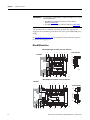
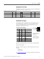
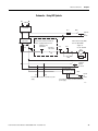
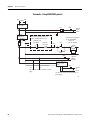
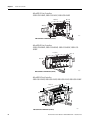
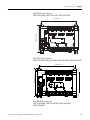
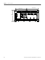
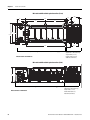
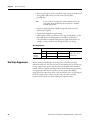
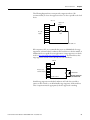
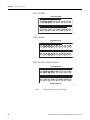
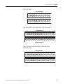
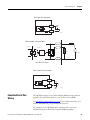
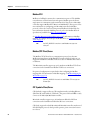
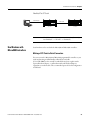
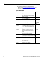
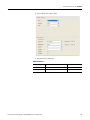
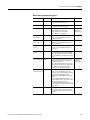
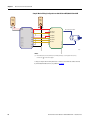
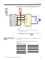
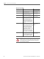
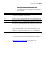
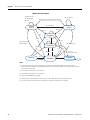
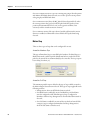
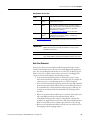
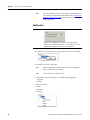
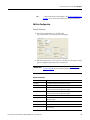
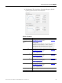
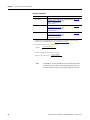
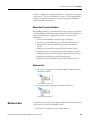
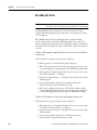
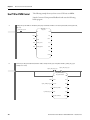
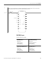
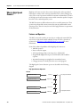
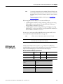
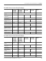
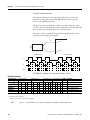
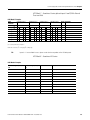
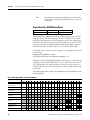
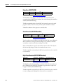
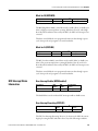
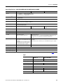
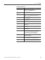
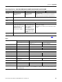
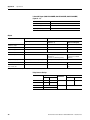
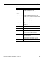
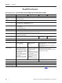
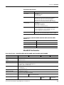
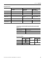
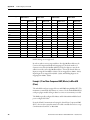
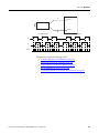
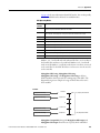
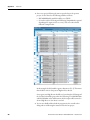
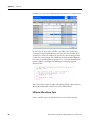
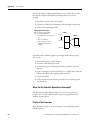
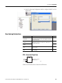
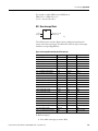
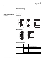
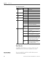
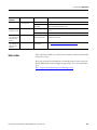
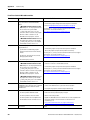
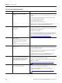
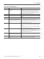
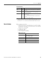
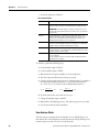
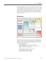
Motion Control with PTO and PWM Chapter 7
Sample Motion Wiring Configuration on 2080-LC30-xxQBB/2080-LC50-xxQBB
24V
Power
Supply
1
2
+
+
+CM0
+CM1
Pin 1, 2
O-03
Pin 14(DIR-)
Pin 25(DIR+)
O-06
Pin 3(Enable)
O-07
Pin 7(RST)
-CM0
-CM1
Encoder signal cable
Motor
O-00
Pin 12(CLK-)
Pin 49(CLK+)
Encoder
2080-LC30-xxQBB
2080-LC50-xxQBB
+DC 24
-DC 24
_
Kinetix3
–
24V
Power
Supply
Motor power cable
46047
Notes:
(1) Drive Enable (Pin 3) and Reset Drive (Pin 7) will be operating as sinking inputs when (Pin 1,2)
connected to + of the Power Supply 2.
To help you configure Kinetix3 drive parameters so the drive can communicate and be controlled
by a Micro830/Micro850 controller, see publication CC-QS025.
Motion Control Function
Blocks
Motion control function blocks instruct an axis to a specified position, distance,
velocity, and state.
Function Blocks are categorized as Movement (driving motion) and
Administrative.
Administrative Function Blocks
Function Block Name
Function Block Name
MC_Power
MC_ReadAxisError
MC_Reset
MC_ReadParameter
MC_TouchProbe
MC_ReadBoolParameter
MC_AbortTrigger
MC_WriteParameter
MC_ReadStatus
MC_WriteBoolParameter
MC_SetPosition
Rockwell Automation Publication 2080-UM002F-EN-E - December 2013
67