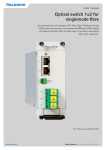
1
User manual
CMA module adapters and
CLP line protection modules
CMA0x5 module adapters are intentended for
stand-alone installations of CFO series units.
CLP line protection modules providing a common mode
interference rejection for video inputs and a surge/transient
voltage protection for all audio and data lines.
CMA0x5 & CLP00x user manual, 59300322, rev003
Contents
CMA015, 025 & CMA035 - Module adapters.............................................................................................................. 1
General............................................................................................................................................................... 1
Installation........................................................................................................................................................... 1
Mounting CLP line series modules..................................................................................................................... 4
Supply voltage..................................................................................................................................................... 5
Technical Specifications........................................................................................................................................... 6
CLP - Video and Line Protection Series Introduction.................................................................................................. 7
General............................................................................................................................................................... 7
Features.............................................................................................................................................................. 7
CLP - Front and top panel......................................................................................................................................... 8
Front panel - interfaces towards CFO................................................................................................................. 8
Top panel - interfaces towards external devices................................................................................................. 9
Stand-alone installation..................................................................................................................................... 10
Dismounting...................................................................................................................................................... 13
Configurations................................................................................................................................................... 14
Technical Specifications......................................................................................................................................... 16
Legal declarations................................................................................................................................................... 17
CMA0x5 & CLP00x user manual, rev003
CMA015, 025 & CMA035 - Module adapters
The CMA015, 025 & CMA035 module adapters are intentended
for stand-alone installations of CFO series units.
Welcome, and thank you for purchasing Teleste’s CFO Products.
General
The CMA015 is intended for stand-alone installations of 5HP wide
CFO series units.
The CMA025 is intended for stand-alone installations of 10HP wide
CFO series units. It can be used also for installation of two 5HP wide
CFO units.
The CMA035 is intended for stand-alone installations of 15HP wide
CFO series units. It can be used also for installation combinations of
either 3 x 5HP units or 1 x 5HP and 1 x 10HP units.
Installation
The module adapter is to be mounted to a vertical installation surface by
the means of three screws. The slot for the CFO card unit should point to
the left. Installation location must be a dry indoor environment*.
To insert a CFO card unit into the module adapter, push the unit along
the guide rails into module until the unit is firmly attached.
Secure the plug-in unit with the upper and lower locking screws.
0
23.5
35.5
164.1
176.1
197.4
210.9
5.2
Ø10.5
CMA015
(Left side view)
116
133
108
(7)
0
93.5
105.5
35.5
CMA015 Dimensions
* IP housing classification is IP20.
CMA module adapters user manual
1
23.5
0
23.5
35.5
5.2
35.5
164.1
176.1
197.4
210.9
Ø10.5
CMA025
(Left side view)
116
133
108
(7)
0
93.5
105.5
54.2
CMA025 Dimensions
0
164.1
176.1
197.4
210.9
5.2
Ø10.5
CMA035
(Left side view)
116
133
108
(7)
0
93.5
105.5
79.6
CMA025 Dimensions
2
CMA module adapters user manual
By using an optional mounting kit (item code CIK002) a rear side
mounting is enabled (see also picture on next page)..
220
33.5
141.5
Ø5.2
Ø10.5
58
CMA
13
5.2
18.5
14
10.5
30
43
61.5
119.5
CIK002 Dimensions
CMA module adapters user manual
Wall
3
CMA025 module adapter with CIK002 rear
mounting kit.
For limited space installation the CMA
module adapters can be rear-mounted by
means of an optional installation kit CIK002.
Mounting CLP line series modules
164.1
23.5
0
The CMA015, 025 and 035 has a direct mounting interface for CLP line
series modules. Please see section CLP line protection modules, page 7.
99.8
99.8
118
93.5
0
Ø8 (3pcs)
CMA0x5 module adapter (right side view, compatible for CLP mounting)
4
CMA module adapters user manual
Supply voltage
+12 V DC Supply voltage is provided by a CPS25x series mains adapter
(12 V DC, 3.3 A). The DC socket (2-pin removable screw, located on
top) is supplied with the CMA module adapter. See instructions provided
with CPS25x to connect the DC wires with correct polarity.
Supply voltage (+ 12 V DC) is feeded trough sepate power connector.
CMA
CPS
2
1
2
3
1
3
DC connection polarity
CMA025 and CMA015 module adapters (top view)
1. Supply voltage connector
2. Grounding connector
3. Grounding connector for CLP line protection units
CMA module adapters user manual
5
Technical Specifications
CMA015/025/035 module adapters& CIK002 Optional mounting kit
Dimensions (H x W x D) mm
133 • 35.5 • 210.9
CMA015
133 • 61.2 • 210.9
CMA025
133 • 86.6 • 210.9
CMA035
171.5 • 119.5 • 220
CIK002
Weight
0.60 kg
CMA015
0.70 kg
CMA025
0.85 kg CMA035
0.55 kg
CIK002
230 VAC - 12 VCD / 3.3 A
EU mains cable
CPS251/252/253 12VDC Mains Adapters
CPS251 CPS252
230 VAC - 12 VCD / 3.3 A
UK mains cable
CPS253
115 VAC - 12 VCD / 3.3 A
US mains cable
Dimensions (H x W x D) mm
33 • 56 • 121 mm (1.3 • 2.2 • 4.8”)
Weight
0.250 kg (0.551 lbs)
Output current
3.3 A
at +40°C
2.1 A
at +74°C
Operating temperature
-34...+74°C (-29...165°F)
33
56
121
1830
60
38
8
Typical values unless otherwise stated
6
CMA module adapters user manual
CLP - Video and Line Protection Series Introduction
CLP001:
CLP002:
CLP003:
CLP004:
Single channel video coil and line protection
Line protection only
Four channel video coil (ch1...4)
Four channel video coil (ch5...8)
Welcome, and thank you for purchasing Teleste’s CFO Products.
General
CLP line protection modules are meant for standalone CFO installations on sites where is a clear need either for overvoltage protection
(lightning) or mains hum (50 Hz and harmonics) suppression, or even
for both. CLP series units are designed to be attached over a CMA
series standalone adapter and several units can be bundled over each
other. Therefore alternative module combinations can be provided for
either single channel, 4-channel or even 8- channel video modem
operation. (Supported video modems are CFO4x0 / 8x0 / x61 / x91 and
4-ch / 8-ch CEV models).
The design for video protection is based on inductor coils that reduce
the effect of common mode type interference easily induced into coaxial
cable carrying video signal on areas where strong or rapidly changing
electrical fields do exist. A mimimum attenuation or any other effect is
exposed to the video signal itself.
In addition to above all signal lines used are provided with gas discharge
tubes as efficient surge voltage arrestors as well as with protective
diodes for transient overvoltages.
All connection cables needed between video modem and CLP unit(s)
are included in the package. All the wires/cables needed between
external devices and CLP units can be easily connected to blocks of
screw terminal connectors at the top of the unit. For camera/video
connections units are provided with isolated BNC connectors.
The permitted operational temperature range for stand-alone devices
is -34...+74 °C.
Features
•
•
•
•
•
•
CLP line protection units user manual
Unique design.
Line protection for all video/data/audio/cc channels.
Provides failsafe operation for standalone installations exposed to
lightning etc.
Mechanically compact and ruggedised.
Enviromental conformance.
Compatible with CMA installation systems.
7
CLP - Front and top panel
CLP001
CLP002
CLP003
CLP004
1
VIDEO
2
ETH (CFO)
DATA / CCL
AUDIO
6
7
ETH (EXT)
DATA
AUDIO
DATA / CCL
5
ETH (CFO)
4
ETH (EXT)
3
DATA
VIDEO 1
9
8
VIDEO 5
10
VIDEO 2
VIDEO 6
VIDEO 3
VIDEO 7
VIDEO 4
VIDEO 8
CLP001, CLP002, CLP003 and CLP004 front panel mechanical connections.
Front panel - interfaces towards CFO
1. Video intput(s) (BNC female).
2. Video output (BNC female).
3. DATA 1 & CCL connector (RJ-45 female).
4. DATA 2 & 3 connector (RJ-45 female).
5. AUDIO 1 & 2 connector (RJ-45 female).
6. ETH (CFO), Ethernet bridge port, connector (RJ-45).
7. ETH (EXT) connector (RJ-45).
8. Locking mechanism.
9. Video outputs, channels 1...4 (BNC female).
10.Video outputs, channels 5...8 (BNC female).
These interfaces are connected with the respective interfaces on
the video modem (required cables are included in the package).
8
CLP line protection units user manual
CLP001
1
CCL
4
DATA 1
1
CCL
IN
1
CLP002
GND
OUT
CCL
IN+
IN-
CLP003
GND
OUT
GND
4
IN+
IN-
5
IN+
IN-
GND
GND
IN
VIDEO 1
IN+
IN-
GND
1
AUDIO 1
GND
5
1
OUT+ OUT-
IN
DATA 3 3
GND
VIDEO 2
1
AUDIO 2
GND
1
IN-
OUT+ OUT-
GND
AUDIO 1
OUT+ OUT-
GND
IN+
IN-
7
5
1
8
AUDIO 2
AUDIO
OUT
VIDEO
5
AUDIO
IN+
6
DATA
OUT+ OUT-
5
AUDIO
OUT
5
DATA
OUT+ OUT-
DATA 3 3
DATA
OUT+ OUT-
DATA 2
1
DATA
OUT
1
4
DATA 1
1
5
DATA
OUT+ OUT-
3
CCL
IN
DATA 2
1
DATA
OUT
2
1
5
9
5
AUDIO
IN+
IN-
OUT+ OUT-
VIDEO 3
VIDEO 4
VIDEO 7
VIDEO 8
GND
IN+
IN-
10
CLP004
VIDEO 5
VIDEO 6
11
CLP001, CLP002, CLP003 and CLP004 top panel mechanical connections.
Top panel - interfaces towards external devices
1. Video output (BNC female).
2. CLL connector (Screw terminal, 4-pin).
3. DATA 1 connector (Screw terminal, 5-pin).
4. DATA 2 connector (Screw terminal, 5-pin).
5. DATA 3 connector (Screw terminal, 3-pin).
6. AUDIO 1 connector (Screw terminal, 5-pin).
7. AUDIO 2 connector (Screw terminal, 5-pin).
8. Video input (BNC female).
9. Grounding cable.
10.Video inputs, channels 1...4 (BNC female).
11.Video inputs, channels 5...8 (BNC female).
These interfaces are connected with the external devices
(cables are not included).
CLP line protection units user manual
9
1
CCL
4
DATA 1
1
CCL
IN
GND
OUT
5
DATA 2
1
DATA
OUT
IN+
IN-
GND
5
1
DATA
OUT+ OUT-
IN+
IN-
GND
DATA 3 3
1
AUDIO 1
DATA
OUT+ OUT-
IN
GND
5
1
AUDIO 2
AUDIO
OUT
OUT+ OUT-
Connector
CCL
Data 1
Data 2
Data 3
Audio 1
Audio 2
GND
5
AUDIO
IN+
IN-
Pin
OUT+ OUT-
GND
IN+
IN-
Signal
1
in
2
GND
3
out
4
out
1
in +
2
in -
3
GND
4
out +
5
out -
1
in +
2
in -
3
GND
4
out +
5
out -
1
in
2
GND
3
out
1
out +
2
out -
3
GND
4
in +
5
in -
1
out +
2
out -
3
GND
4
in +
5
in -
CLP001 and CLP002 internal connectors pinout (pin numbering is
labelled to the CLP unit).
Stand-alone installation
CLP series units are designed to be attached over a CMA series
standalone adapter and several units can be bundled over each other.
The following illustrations show assembly phases, follow the installation
steps accordingly.
Mount the CLP module over the module adapter by pressing the sides
together and line up them so that the brackets on the CPL module fit
into grooves in the CMA025 module adapter. (as you can see on the
10
CLP line protection units user manual
picture below). Then slide the CPL module backwards until you hear
the latch catching the locked position (at the bottom of the module).
Repeat this procedure for all modules, that are needed in the installation.
4
1
CCL
Note! If units are aligned correctly
they will find their position with
a minimum use of force.
4
1
DATA 1
5
1
DATA 2
5
1
DATA 3 3
1
AUDIO 1
5
1
AUDIO 2
5
VIDEO
Assembly figure 1.
An example of CPL001 mounting over
CMA025 module adapter. This setup
provides protection to e.g. CRT161
(1-ch video transmitter).
1.
2.
3.
4.
1
2
3
CLP001 1-ch Video coil & Line protection
Grounding connector for CLP
CMA025 Module adapter
Bracket
CLP line protection units user manual
11
1
CCL
4
1
DATA 1
VIDEO 1
5
1
DATA 2
VIDEO 2
5
1
DATA 3 3
VIDEO 3
1
AUDIO 1
VIDEO 4
5
1
AUDIO 2
5
Assembly figure 2.
An example of CPL002 and CLP003
mounting over CMA025 module adapter.
This setup provides protection to e.g.
CRT461 (4-ch video transmitter).
1. CLP003 4-ch Video coil (ch 1...4)
2. CLP002 Line protection
3. Grounding connector for CLP
4. CMA025 Module adapter
12
1
2
3
4
Once all CLP modules are firmly attached to their positions connect all
grounding cables from CLP modules to the common grounding point
next to DC input.
CLP line protection units user manual
Dismounting
Detach first the grounding wire. To remove the CLP module, push
the latch at bottom of the unit to release the locking, and pull the
module forward.
Assembly figure 3.
CLP line protection units user manual
13
Configurations
Alternative module combinations can be provided for either single
channel, 4-channel or even 8- channel video modem operation.
(Supported video modems are CFO4x0 / 8x0 / x61 / x91 and
4-ch / 8-ch CEV models).
Required interconnection cables are included with the units.
1-ch TX:
CMA025 Module adapter
CLP001 1-ch Video coil & Line protection
VIDEO
DATA / CCL
OPTICAL TRANSMITTER
ETH (EXT)
MODULE
ETHERNET BRIDGE
LINK STATUS
ETH (CFO)
MGMT
AUDIO
AUDIO
DATA
DATA
DATA / CCL
VIDEO 1
Cabling figure 1.
Note! The cables included in the package are standard BNC BNC 75 ohm coaxial cables for video and direct-connected CAT5
cables for audio/data/CCL/Ethernet signals.
14
CLP line protection units user manual
4-ch TX: CMA025 Module adapter
CLP002 Line protection
CLP003 4-ch Video coil (ch 1...4)
DATA / CCL
OPTICAL TRANSMITTER
VIDEO 1
DATA
DATA / CCL
VIDEO 1
AUDIO
DATA
VIDEO 2
VIDEO 2
ETH (CFO)
MGMT
AUDIO
VIDEO 3
VIDEO 4
ETHERNET BRIDGE
LINK STATUS
VIDEO 3
ETH (EXT)
MODULE
VIDEO 4
Cabling figure 2.
8-ch TX:
CMA035 Module adapter
CLP002 Line protection
CLP003 4-ch Video coil (ch 1...4)
CLP004 4-ch Video coil (ch 5...8)
VIDEO 5
VIDEO 2
VIDEO 6
VIDEO 1
VIDEO 5
VIDEO 2
VIDEO 6
VIDEO 3
VIDEO 7
VIDEO 4
VIDEO 8
VIDEO 4
VIDEO 8
ETH (EXT)
MODULE
ETHERNET BRIDGE
LINK STATUS
ETH (CFO)
VIDEO 7
MGMT
VIDEO 3
AUDIO
AUDIO
DATA
DATA / CCL
VIDEO 1
DATA
DATA / CCL
OPTICAL TRANSMITTER
Cabling figure 3.
CLP line protection units user manual
15
Technical Specifications
Video protection
Data
Common mode suppression 23 dB @50Hz
Number of channels
3 bi-directional
24 dB @100Hz
Data 1 & 2 format
RS232/422/485
Common mode current
300 mA max @ 1kHz
Data 3 format
RS232
Insertion loss 0.12 dB Data 1 & 2 connectors
RJ-45 female/
Sync to Bar Top 1V
990,4 mV
2 x 5-pin removable screw terminal
Pulse/Bar Ratio Err
-0,50 %
Data 3 connectors
RJ-45 female/
Chr/Lum Delay Ineq
-2,8 ns
3-pin removable screw terminal
Lum. Nonlin. Dist
0,2 %
Peak Diff Gain
0,3 %
Multiburst Packet 97,5% Flag
99,1% (ref 3.58 MHz)
Multiburst Packet 97.0% Flag
97,1% S/N Lum-wgtd (567)
86,5 dB
Surge voltage protection
GDT 150 V
(DC...5,5 MHz)
Contact Closure
Number of channels
1 bi-directional
(ref 4.10 MHz)
Connectors
RJ-45 female/
4-pin removable screw terminal
Failsafe
Ethernet Interface
Line Protection
Transient voltage protection
CLP001, CLP002
TVS Diodes
Number of ports
1
Port standard
10/100Base-TX FE Bridge
Audio lines
15 V
differential
Compliance
IEEE802.3, IEEE802.3U
15 V
single ended
Connectors
RJ-45 female
Data Line 1
48 V
differential
24 V
single ended
General
Data Lines 2 & 3
15 V
differential
15 V
single ended
CCL out
15 V
differential
15 V
single ended
CCL in
15 V
single ended
Surge voltage protection GDT 200 V
Failsafe, all lines
Vibration tests
IEC 60068-2-6 Fc,
BS 2011-2.1 Fbd,
ref. IEC 60068-2-64 Fh,
IEC 60068-2-27 Ea
Video
Channels
1 CVBS
CLP001
4 CVBS
CLP003 (ch1...4)
4 CVBS
CLP004 (ch 5...8)
Connectors
BNC female
CLP001, CLP002
CLP001, CLP002
Supply voltage
-
passive unit
Current consumption
-
passive unit
(H x W x D)
117 • 27 • 230 mm
CLP001
117 • 27 • 230 mm
CLP002
129 • 27 • 230 mm
CLP003, CLP004
Weight
0.8 kg
CLP001
0.7 kg
CLP002
1.0 kg
CLP003, CLP004
Operating temperature
-34...+74 °C
Storage temperature
-40...+85 °C
Humidity
0...95 %
Dimensions (with connectors)
non condensing
Notes
Typical values unless otherwise stated
Audio
Number of channels
2 bi-directional
Connectors
RJ-45 female/
2 x 5-pin removable screw terminal
16
CLP001, CLP002
CLP line protection units user manual
Legal declarations
Copyright © 2012 Teleste Corporation. All rights reserved. Teleste is a registered trademark of Teleste Corporation. Other product and service marks are
property of their respective owners.
This document is protected by copyright laws. Unauthorized distribution or
reproduction of this document is strictly prohibited.
Teleste reserves the right to make changes to any of the products described in this
document without notice and all specifications are subject to change without notice.
Current product specifications are stated in the latest versions of detailed product
specifications.
To the maximum extent permitted by applicable law, under no circumstances shall
Teleste be responsible for any loss of data or income or any special, incidental,
consequential or indirect damages howsoever caused.
Teleste Corporation
P.O. Box 323
FI-20101 Turku
FINLAND
User manual revision history note:
The latest version is always available in pdf-format on our web site:
www.teleste.com
www.teleste.com