1
User manual
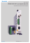
CFO331/521 one channel video link
CFO First Mile series consist of fibre optic modems which provide a high
quality and losless video transmission for variety of CCTV applications
CFO331/521 video link user manual, 59300260, rev005
Contents
CFO331/521 - one channel video links........................................................................................................................ 1
General............................................................................................................................................................... 1
Features.............................................................................................................................................................. 1
CPT - Mini sized stand-alone video transmitter..................................................................................................... 2
General............................................................................................................................................................... 2
Stand-alone installation....................................................................................................................................... 2
Video connection and indicator led..................................................................................................................... 2
Data connection.................................................................................................................................................. 3
Contact Closure loop (CCL) connection............................................................................................................. 4
Video Source Alarm (VSA)................................................................................................................................. 4
Link status indicator led....................................................................................................................................... 5
Fibre connection................................................................................................................................................. 5
CRR - Single channel optical receiver..................................................................................................................... 6
General............................................................................................................................................................... 6
Frame installation................................................................................................................................................ 6
Stand-alone installation....................................................................................................................................... 6
Video connection and indicator led..................................................................................................................... 6
Data connection.................................................................................................................................................. 7
Contact Closure loop (CCL) connection............................................................................................................. 9
Video Source Alarm (VSA)................................................................................................................................. 9
Link status indicator led..................................................................................................................................... 10
Alarm connection.............................................................................................................................................. 10
Fibre connection............................................................................................................................................... 10
Technical Specifications......................................................................................................................................... 11
CFO331/521 video link user manual
CFO331/521 - one channel video links
CFO331/521 singlemode 1 channel video link for uni-directional
video and bi-directional data and contact closure transmission
for variety of CCTV applications.
Vx1 Dx1 C x1
C
Welcome, and thank you for purchasing Teleste’s CFO Products.
General
These one channel video link units offer a 10-bit video transmission with
one bi-directional data and one contact closure channel over one
singlemode fibre (CFO521) or over one multimode fibre (CFO331).
PAL, NTSC and CVBS video formats are supported to provide
a transparent video transmission. All common data protocols are
supported as well and are easily configured by DIP switches. Optical
transmission is based on class 1M laser operation. The multiplexed data
stream of 202.5 Mbps enables a full quality and a real-time video
transmission in one multimode fibre up to 5 km (CFO331), singlemode
fiber up to 40 km (CFO521) typical transmission distance.
The primary application is a point-to-point transmission from camera to
monitoring centre. In advanced video network systems the CFO331/521
offers a flexible way for first mile transfer to the nearest collection point
of a larger scale network.
The CPT331/521 stand-alone transmitters are capable of using both 12
VDC or 24 VAC supply voltage. CPT331/521 unit is a compact size
housing for special stand-alone installations requiring minimal
installation space. Also as an optional DIN rail mounting is
possible (item code CIK001).
All CRR331/521 units are compatible with all CFO rack systems.
Stand-alone options are available with the CMA015 module adapter
and separared CPS series mains adapter.
As with all CFO platform products these specific models do meet
all typical EMC as well as other environmental and manufacturing
related requirements.
Features
• High performance uncompressed zero delay digital video transmission, SNR 67 dB typical, 10 bit video sampling
• One CVBS (PAL/NTSC) video channel
• One bi-directional data interface, compatible with EIA232/422/485
• Data rate up to 230 kbps
• One bi-directional contact closure
• Transmission on one multimode fibre up to 5 km (CFO331)
• Transmission on one singlemode fibre up to 40 km (CFO521)
• Units for rack mount or stand-alone installations
• Mechanically compact and ruggedised
• Transmitter unit available in a special small-size stand-alone
design (CPT)
CFO331/521 video link user manual
1
CPT - Mini sized stand-alone video transmitter
CAUTION:
THESE OPTICAL UNITS USES CLASS 1M LASER DIODE.
DO NOT STARE INTO BEAM OR VIEW DIRECTLY WITH OPTICAL
INSTRUMENTS. APPLICABLE STANDARD
IEC60825-1: 2001
side view
1
2
3
CPT521
4
CPT331/521 Optical Transmitter
1) Optical input/output (SC/PC)
2) Link status indicator led
3) Video indicator led
4) Screw terminal connector (10-pin)
5) Video input (BNC female)
6) DIP switches for data
connection selection
7) Grounding
See further information on
dedicated sections.
7
5
General
6
The CPT331/521 is a one channel optical transmitter for uni-directional
video transmission with one bi-directional data, and one contact closure
channel. The current consumption is max. 250 mA (+12V DC).
Stand-alone installation
The CPT331/521 units are designed for stand-alone installation. The unit
should be mounted with a help of wall bracket to a installation place.
The supply voltage can be either +12V DC or 24V AC. The supply
voltage is provided by either a surveillance camera unit, or by an
external mains adapter. The permitted supply voltage range are
10.5...14 VDC and 16...28 VAC. In DC use the +12V DC supply voltage
is supplied by the means of a separate mains adapter with a regulated
output, (e.g. CPS251). The permitted operational temperature range for
CPT331/521 is from –34 to +74 °C.
Wall bracket dimensions.
Video connection and indicator led
The impedance of the video connection (BNC female) is 75 Ω.
The nominal input level is 1 Vpp. Video connection is equipped with
the dual colour VIDEO led on the front panel. See next page for
explanation of VIDEO indicator led’s lights.
2
CFO331/521 video link user manual
Data connection
The CFO331/521 link provides one bi-directional data channel
(CPT <--> CRR). The connector in use is a screw terminal connector.
Available data modes for data channel are RS232, RS422, RS485-2w
and RS485-4w. See table below how to connect the desired data mode.
The desired data connection must be confirm by the means of DIP
switches. The desired data mode settings for data channel can be set
by the means of receiver’s DIP switches (see page 7 for detailed
description). The default factory setting is RS485-2w + dwelltime
75 µs, no line bias and no term.
Pin
RS232
RS422
in -
in / out -
in -
Data in+
in
in +
in / out +
in +
Data out-
out
out -
out -
out +
out +
Data inThe screw terminal connector containing
supply voltage, data and contact closure
connections (10-pin).
Data out+
1 2 3 4 5 6
CPT331/521 DIP switches.
Transmitter data channel mode must set
from receiver unit.
RS485-4w
Screw terminal connector’s data pinout.
Data contact
ON
RS485-2w
DIP switch position
1
2
3
4
5
off
off
off
off
off
RS422
off
off
RS485-2w
on
on
off
off
RS232
RS485-4w
- line bias
on
on
- no line bias
off
off
- term
on
- no term
off
VSA
6
on
Data connection settings.
Note! If data cabling is requiring signal ground, the CC INterminal can be used for this purpose.
CFO331/521 video link user manual
3
Contact Closure loop (CCL) connection
The CFO331/521 link provides one bi-directional contact closure
channel line (CPT <--> CRR). The CCL input is a normal short circuit on/
off - signal between connector’s contact pins CC in+ and CC in(= signal ground). The CCL output is a normal relay on/off - signal
(24V / 1A) between connector’s contact pins (CC out+ and CC out-).
The connector in use is a screw terminal connector.
The CCL output channel can be alternatively configured for VSA
(Video Source Alarm) usage with DIP switch. The default factory
setting is VSA off.
Pin
Description
CC in-
Contact closure input (ground)
CC in+
Contact closure input
CC out
Contact closure output (relay)
CC out
Contact closure output (relay)
Screw terminal connector’s CC pinout.
Video Source Alarm (VSA)
The screw terminal connector and CCL
connection.
The CCL output channel can be alternatively configured for Video Source
Alarm (VSA) monitoring. Instead of normal CCL use, the CCL output can
be used to provide a VSA signal if a loss of video signal occurs.
When VSA mode is enabled at transmitter and if video signal is missing
(e.g. a camera malfunction, link otherwise operates normally), the CCL
output pins are closed. Using VSA at just one end of the link enables the
opposite path to be used for standard CCL operation (simplex). In case
when VSA is enabled both at transmitter and receiver, the CCL channel
is no longer available for any other use. When VSA is disabled the CCL
channel is available for normal use in both directions. The VSA mode
can be set on/off by the means of DIP switch (see previous page).
Note! Video detection circuitry has 20 sec delay before VSA
alarm is activated/inactivated.
CPT331/521
“VSA OFF”
CRR331/521
“VSA ON”
CPT331/521
“VSA ON”
CRR331/521
“VSA OFF”
CCL and VSA connection examples.
4
CFO331/521 video link user manual
Link status indicator led
The CPT331/521 contains LINK STATUS indicator led on the front panel
which inform generic status of unit.
Colour
Status
Green
Optical signal level is adequate and synchronization on link
level is achieved
Blinking
Yellow/Green
Optical signal level is adequate, but no synchronization on
link level is achieved
Yellow
Optical signal is missing or input level is too low
LINK STATUS indicator operation.
INVISIBLE LASER
RADIATION
CLASS 1
front view
Fibre connection
The optical connector is of the type SC/PC. The optical output level
is constant and cannot be adjusted. For optical specifications please
see page 11. When installing the fibre optic cable, do not exceed the
minimum bending radius when connecting cable to the system.
Note! For correct optical operation ensure that all optical
connectors are cleaned immediately before mating. Connectors
should always be cleaned using high purity alcohol (e.g. methyl or
isopropyl alcohol). Dry the surfaces using clean compressed air
or other equivalent pressurised gas. The optical connectors on
the equipment should always be protected with dustcaps when
there is no fibre inserted.
Note! Video, data and CCL outputs are disabled until optic link is
properly established.
Optical connection meets class 1M laser safety requirements of IEC
60825-1: 2001 and US department of health services 21 CFR 1040.10
and 1040.11 (1990) when operated within the specified temperature,
power supply and duty cycle ranges.
The optical connector type is SC/PC.
CFO331/521 video link user manual
5
CRR - Single channel optical receiver
General
The CRR331/521 is a one channel optical receiver for uni-directional
video transmission with one bi-directional data and one contact closure
channel. The current consumption is max. 250 mA (+12V DC).
Frame installation
VIDEO
OUT
CC
OUT
IN+
The CRR331/521 module is to be pushed along the guide rails into the
installation frame (e.g. CSR216 or 316 series) and secured with the two
locking screws. The unit can be freely positioned in any slot in the
frame. The empty positions in the frame should be blanked off with
cover plates. The supply voltage is to be provided by a CPS384 or
CPS390 power supply unit which are installed back of frame.
Stand-alone installation
INOUT+
DATA
OUTIN+
IN-
SC/PC
LINK STATUS
The unit can be installed for stand-alone use by using a CMA015
module adapter. The module should be mounted to a vertical surface.
The +12 VDC supply voltage is supplied by the means of a separate
mains adapter with a regulated output, (e.g. CPS251).
The permitted supply voltage range is 10.5...14 VDC. The current
consumption is 250 mA. The permitted operational temperature range for
CRR331/521 is from –34 to +74 °C.
Video connection and indicator led
INVISIBLE LASER
RADIATION
CLASS 1
CRR521
OPTICAL
RECEIVER
The impedance of the video connection (BNC female) is 75 Ω. The
nominal input/output level is 1 Vpp. Video connection is equipped with
the dual colour VIDEO led on the front panel. See table below for
explanation of VIDEO indicator led’s lights.
CRR331/521 Optical Receiver
1) Locking screw (2 pcs)
2) Video output (BNC female) and
video indicator led
3) Data & CC connector
(screw terminal, 10-pin)
4) Optical input/output (SC/PC) and
link status indicator led
5) Handle (with unit information)
See further information on
dedicated sections.
6
CFO331/521 video link user manual
Data connection
The screw terminal connector containing
data and contact closure connections.
The CFO331/521 link provides one bi-directional data channel
(CPT <--> CRR). The connector in use is a screw terminal connector.
Available data modes for data channel are RS232, RS422, RS485-2w
and RS485-4w. See table below how to connect the desired data
mode. The desired data connection must be confirm by the means
of DIP switches.
Pin
RS232
RS422
RS485-2w
RS485-4w
in -
in / out -
in -
in +
in / out +
in +
Data inData in+
in
Data out-
out
Data out+
out -
out -
out +
out +
Screw terminal connector’s data pinout.
Data contact
ON
1 2 3 4 5 6
CRR331/521 Data connection DIP
switches (SW2).
RS232
DIP switch position
1
2
3
4
5
off
off
off
off
off
RS422
off
off
RS485-2w
on
on
RS485-4w
off
off
- line bias
- no line bias
- term
on
- no term
off
on
on
off
off
VSA
6
on
Data connection settings (SW2).
Note! If data cabling is requiring signal ground, the CC INterminal can be used for this purpose.
CFO331/521 video link user manual
7
The desired data mode settings including dwelltime settings for RS4852w can be set by the means of DIP switches. The default factory
setting is RS485-2w + dwelltime 75 µs, no line bias and no term.
RS485-2w Dwelltime settings
Dwelltime ms
Dip 1
Dip 2
Dip 3
Tx data
Dip 4
Dip 5
Rx data
Dip 6
Dip 7
Dip 8
Data channel
mode
0,01
on
on
on
on
on
on
on
on
RS232
0,02
off
on
on
on
off
on
off
on
RS422
0,04
on
off
on
on
on
off
on
off
RS485-2w
0,075
off
off
on
on
off
off
off
off
RS485-4w
0,1
on
on
off
on
0,2
off
on
off
on
0,4
on
off
off
on
0,6
off
off
off
on
1
on
on
on
off
1,2
off
on
on
off
2
on
off
on
off
3
off
off
on
off
4
on
on
off
off
6
off
on
off
off
8
on
off
off
off
10
off
off
off
off
Data mode selection and RS485-2w dwelltime settings (SW1).
CRR331/521 DIP switches (SW1 & SW2).
8
CFO331/521 video link user manual
Contact Closure loop (CCL) connection
The CFO331/521 link provides one bi-directional contact closure
channel line (CPT <--> CRR). The CCL input is a normal short circuit on/
off - signal between connector’s contact pins CC in+ and CC in(= signal ground). The CCL output is a normal relay on/off - signal
(24V / 1A) between connector’s contact pins (CC out+ and CC out-).
The connector in use is a screw terminal connector.
The CCL output channel can be alternatively configured for VSA
(Video Source Alarm) usage with DIP switch. The default factory
setting is VSA off.
Pin
Description
CC in-
Contact closure input (ground)
CC in+
Contact closure input
CC out
Contact closure output (relay)
CC out
Contact closure output (relay)
Screw terminal connector’s CC pinout.
Video Source Alarm (VSA)
The screw terminal connector and
CCL connection.
The CCL output channel can be alternatively configured for Video Source
Alarm (VSA) monitoring. Instead of normal CCL use, the CCL output can
be used to provide a VSA signal if a loss of video signal occurs.
When VSA mode is enabled at transmitter and if video signal is missing
(e.g. a camera malfunction, link otherwise operates normally), the CCL
output pins are closed. Using VSA at just one end of the link enables the
opposite path to be used for standard CCL operation (simplex). In case
when VSA is enabled both at transmitter and receiver, the CCL channel
is no longer available for any other use. When VSA is disabled the CCL
channel is available for normal use in both directions. The VSA mode
can be set on/off by the means of DIP switch (see previous page).
Note! Video detection circuitry has 20 sec delay before VSA
alarm is activated/inactivated.
CPT331/521
“VSA OFF”
CRR331/521
“VSA ON”
CPT331/521
“VSA ON”
CRR331/521
“VSA OFF”
CCL and VSA connection examples.
CFO331/521 video link user manual
9
Link status indicator led
The CRR331/521 contains LINK STATUS indicator led on the front
panel which inform generic status of unit.
Colour
Status
Green
Optical signal level is adequate and synchronization on link
level is achieved
Blinking
Yellow/Green
Optical signal level is adequate, but no synchronization on
link level is achieved
Yellow
Optical signal is missing or input level is too low
LINK STATUS indicator operation.
Alarm connection
Alarm at the rear connector of the unit is low open collector output, with
the capability of 30 V/10 mA switching.
Alarm
Description
Reason
B
Link status alarm
No synchronization achieved at
optical input.
Open collector alarms.
INVISIBLE LASER
RADIATION
CLASS 1
front view
Fibre connection
The optical connector is of the type SC/PC. The optical output level
is constant and cannot be adjusted. For optical specifications please
see page 11. When installing the fibre optic cable, do not exceed the
minimum bending radius when connecting cable to the system.
Note! For correct optical operation ensure that all optical
connectors are cleaned immediately before mating. Connectors
should always be cleaned using high purity alcohol (e.g. methyl or
isopropyl alcohol). Dry the surfaces using clean compressed air
or other equivalent pressurised gas. The optical connectors on
the equipment should always be protected with dustcaps when
there is no fibre inserted.
Note! Video, data and CCL outputs are disabled until optic link is
properly established.
Optical connection meets class 1M laser safety requirements of IEC
60825-1: 2001 and US department of health services 21 CFR 1040.10
and 1040.11 (1990) when operated within the specified temperature,
power supply and duty cycle ranges.
The optical connector type is SC/PC.
10
CFO331/521 video link user manual
Technical Specifications
Optical
Contact Closure
Optical transmitter (CPT):
Number of channels
1
Input
dry contact
-14...-8 dBm
Output
24V / 1A (relay)
-31 dBm, min
Switching frequency
5 Hz
Bit rate
202.5 Mbps
Contact closure connector
Screw terminal
Optical connector type
SC/PC
Output wavelength
1310 nm
Output power
Input sensitivity
+/- 50 nm
bi-directional
max
Alarms
Optical receiver (CRR):
Output wavelength
1550 nm
Video
CC output
configurable
Output power
-14...-8 dBm
Optical input signal
B alarm
CRR
Input sensitivity
-31 dBm, min
Bit rate
40.5 Mbps
General
Optical connector type
SC/PC
Supply voltage
10.5...14 VDC
regulated
16...28 VAC
CPT
Supply voltage connector
screw terminal
CPT
Current consumption
250 mA
max
Transmission distance (max) 5 km
40 km
Led/laser classification
+/-50 nm
CPT – CRR , MMF*
CPT – CRR , SMF
EN 60825-1, FDA 21 CRF 1040.10 & 1040.11
*Note! The actual maximum distance may vary depending upon which multimode
cable type is in use.
Dimensions (H x W x D)
CRR 3U • 5HP • 190 mm
without CMA
Video
CPT
35 • 48 • 62 mm
without connectors
Weight
0.2 kg
CPT
0.5 kg
CRR
Video & link status
LED displays
Operating temperature -34...+74 °C
Storage temperature -40...+80 °C
recommended
Humidity 0...95 % non condensing
EMC compatibility
EN61000-6-3, EN50130-4, CE
Number of channels
1
uni-directional
Standard
PAL/NTSC
CVBS
Input level
1 Vpp
Input overload level
1.75 Vpp
Impedance
75 ohm
Sampling resolution
10 bit
Sampling rate
13.5 MHz
Bandwidth
5.5 MHz
Insertion gain
+/-1 dB
C/L gain inequality
4%
C/L delay inequality
40 ns
Differential gain
2%
Differential phase
1°
SNR
67 dB
Video connector
BNC female
-1 dB
Typical values unless otherwise stated
weighted
Data
Number of channels
1
bi-directional
Data format
RS232/422/485
selectable
Data rate
0...230 kbps
Sampling rate
16 MHz
Data connector
Screw terminal
Video
Data
Cc
Video
Data
Cc
multimode
OM1 fibre
CPT331
CRR331
up to 5 km
singlemode
fibre
CPT521
CRR521
up to
40 km
Video
Data
Cc
Alarms
Video
Data
Cc
Alarms
optical
fibre
CPT
CFO331/521 video link user manual
CRR
11
Copyright acknowledgements
Information in this document is subject to change without notice and does not
represent a commitment on the part of Teleste Corporation.
Copyright © Teleste Corporation. All Rights Reserved.
No part of this document may be reproduced, transmitted, stored in a retrieval
system, or translated into any other language without the express permission
of Teleste Corporation.
Teleste Corporation
Video Networks
P.O. Box 323
FIN-20101 Turku
FINLAND
www.teleste.com
WEEE directive
Directive 2002/96/EC of the European Parliament and of the Council on waste
electrical and electronic equipment (WEEE) obliges that producers
appropriately mark electrical and electronic equipment with the symbol
indicating separate collection. This obligation applies to the equipment put on
the market in EU after 13 August 2005.
Teleste devices which belong to the scope of the directive have been marked
with the separate collection symbol shown below. The marking is according to
the standard EN 50419. The symbol indicates that the device has to be
collected and treated separately from unsorted municipal waste.
User manual revision history note:
The latest version is always available in pdf-format on our web site:
www.teleste.com
12
CFO331/521 video link user manual
CFO331/521 video link user manual
13
www.teleste.com