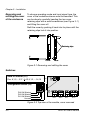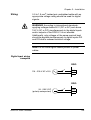
1
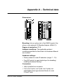
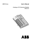
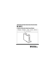
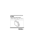
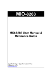
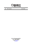
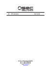
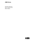
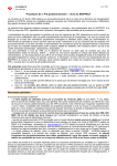
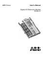
ABB Drives
User’s Manual
Digital I/O Extension Module
RDIO-01
Digital I/O Extension Module
RDIO-01
User’s Manual
3AFE 64485733 REV B EN
EFFECTIVE: 10.2.2003
© 2003 ABB Oy. All Rights Reserved.
Safety Instructions
Overview
This chapter states the general safety instructions that
must be followed when installing and operating the
RDIO-01 Digital I/O Extension module.
The material in this chapter must be studied before
attempting any work on, or with, the unit.
In addition to the safety instructions given below, read
the complete safety instructions of the specific drive you
are working on.
General safety
instructions
WARNING! All electrical installation and maintenance
work on the drive should be carried out by qualified
electricians only.
The drive and adjoining equipment must be properly
earthed.
Do not attempt any work on a powered drive. After
switching off the mains, always allow the intermediate
circuit capacitors 5 minutes to discharge before working
on the frequency converter, the motor or the motor
cable. It is good practice to check (with a voltage
indicating instrument) that the drive is in fact discharged
before beginning work.
The motor cable terminals of the drive are at a
dangerously high voltage when mains power is applied,
regardless of motor operation.
There can be dangerous voltages inside the drive from
external control circuits even when the drive mains
power is shut off. Exercise appropriate care when
working on the unit. Neglecting these instructions can
cause physical injury or death.
RDIO-01 User’s manual
iii
Safety Instructions
iv
RDIO-01 User’s manual
Table of contents
Safety Instructions
Overview . . . . . . . . . . . . . . . . . . . . . . . . . . . . . . . . . . . . . . . . . . . . . . . . . . . 1-iii
General safety instructions. . . . . . . . . . . . . . . . . . . . . . . . . . . . . . . . . . . . . . 1-iii
Table of contents
Chapter 1 – Introduction
Intended audience . . . . . . . . . . . . . . . . . . . . . . . . . . . . . . . . . . . . . . . . . . . . 1-1
Before you start . . . . . . . . . . . . . . . . . . . . . . . . . . . . . . . . . . . . . . . . . . . . . . 1-1
What this manual contains . . . . . . . . . . . . . . . . . . . . . . . . . . . . . . . . . . . . . . 1-2
Chapter 2 – Overview
Overview . . . . . . . . . . . . . . . . . . . . . . . . . . . . . . . . . . . . . . . . . . . . . . . . . . .
The RDIO-01 module . . . . . . . . . . . . . . . . . . . . . . . . . . . . . . . . . . . . . . . . . .
Module layout . . . . . . . . . . . . . . . . . . . . . . . . . . . . . . . . . . . . . . . . . . . . . .
Delivery check . . . . . . . . . . . . . . . . . . . . . . . . . . . . . . . . . . . . . . . . . . . . .
Compatibility . . . . . . . . . . . . . . . . . . . . . . . . . . . . . . . . . . . . . . . . . . . . . . .
Warranty and liability information . . . . . . . . . . . . . . . . . . . . . . . . . . . . . . .
2-1
2-1
2-2
2-3
2-3
2-3
Chapter 3 – Installation
Mounting . . . . . . . . . . . . . . . . . . . . . . . . . . . . . . . . . . . . . . . . . . . . . . . . . . .
Removing and refitting the cover of the enclosure . . . . . . . . . . . . . . . . . . . .
Switches . . . . . . . . . . . . . . . . . . . . . . . . . . . . . . . . . . . . . . . . . . . . . . . . . . . .
Digital input hardware filter suppression . . . . . . . . . . . . . . . . . . . . . . . . . . .
Terminal designations . . . . . . . . . . . . . . . . . . . . . . . . . . . . . . . . . . . . . . . . .
Wiring . . . . . . . . . . . . . . . . . . . . . . . . . . . . . . . . . . . . . . . . . . . . . . . . . . . . . .
Digital input wiring examples . . . . . . . . . . . . . . . . . . . . . . . . . . . . . . . . . .
Node ID selection . . . . . . . . . . . . . . . . . . . . . . . . . . . . . . . . . . . . . . . . . . . . .
Programming . . . . . . . . . . . . . . . . . . . . . . . . . . . . . . . . . . . . . . . . . . . . . . . .
RDIO-01 User’s manual
3-1
3-2
3-2
3-3
3-4
3-5
3-5
3-6
3-6
v
Table of contents
Chapter 4 – Fault tracing
Diagnostic LEDs . . . . . . . . . . . . . . . . . . . . . . . . . . . . . . . . . . . . . . . . . . . . . . 4-1
Option slot installation . . . . . . . . . . . . . . . . . . . . . . . . . . . . . . . . . . . . . . 4-1
I/O Module Adapter installation . . . . . . . . . . . . . . . . . . . . . . . . . . . . . . . 4-1
Appendix A – Technical data
vi
RDIO-01 User’s manual
Chapter 1 – Introduction
Intended
audience
The manual is intended for the people who are
responsible for commissioning and using an RDIO-01
Digital I/O Extension module with the ACS 800 drive.
The reader is expected to have a basic knowledge of
electrical fundamentals, electrical wiring practices and
how to operate the drive.
Before you start
It is assumed that the drive is installed and ready to
operate before starting the installation of the extension
module.
In addition to conventional installation tools, have the
drive manuals available during the installation as they
contain important information not included in this
manual. The drive manuals are referred to at various
points of this document.
RDIO-01 User’s manual
1-1
Chapter 1 – Introduction
What this manual
contains
This manual contains information on the wiring,
configuration and use of the RDIO-01 module.
Safety instructions are featured in the first few pages
of this manual.
Chapter 2 – Overview contains a short description of
the RDIO-01 Digital I/O Extension module, a delivery
checklist and warranty information.
Chapter 3 – Installation contains instructions for
module hardware settings, mounting and cabling.
Chapter 4 – Fault tracing explains fault tracing and
the LED indications of the RDIO-01 module.
Appendix A contains technical data.
1-2
RDIO-01 User’s manual
Chapter 2 – Overview
Overview
This chapter contains a short description of the Digital
I/O Extension module, a delivery checklist and warranty
information.
The RDIO-01
module
The Digital I/O Extension module (RDIO) offers three
digital inputs (24…250 V DC or 110…230 V AC) and
two relay outputs (1250 VA/250 V AC or 5 A/24 V DC).
The isolation voltage between the digital inputs, digital
outputs and power supply is 2.5 kV (1.5 kV between DI2
and DI3).
WARNING! According to international standards,
applying voltages below 50 V (DC or AC) and above
150 V (AC or DC) simultaneously to the digital inputs
and/or outputs of the RDIO-01 is not allowed.
Additionally, only voltages of the same nominal level
should be applied simultaneously to digital inputs DI2
and DI3 due to reduced isolation voltage.
RDIO-01 User’s manual
2-1
Chapter 2 – Overview
Module layout
345
67
89
F0 1 2
Fixing screw (GND)
NODE ID
WD/
INIT
DI3B
DI3A
DI2B
DI2A
X
12
X
11
DI1B
R2NO
DI1A
DI3
X
22
R2CM
R2NC
R1NO
R1CM
X
21
DI2
GND
DI1
R1NC
RDIO-01
CHASSIS
Configuration switch
(behind cover)
DIGITAL I/O EXTENSION
CD
AB E
Node ID selector
Module status LEDs
Fixing screw
(CHASSIS)
123 123
12
1234
Terminal blocks for relay
outputs (X21 and X22)
Terminal blocks for digital
inputs (X11 and X12)
Delivery check
The option package contains:
• RDIO-01 module
• Two screws (M3×8 mm)
• This manual.
Compatibility
2-2
The RDIO-01 is compatible with the ACS 800 Standard
Application Program version ASXR7000 or later.
RDIO-01 User’s manual
Chapter 2 – Overview
Warranty and
liability
information
The warranty for your ABB drive and options covers
manufacturing defects. The manufacturer carries no
responsibility for damage due to transport or unpacking.
In no event and under no circumstances shall the
manufacturer be liable for damages and failures due to
misuse, abuse, improper installation, or abnormal
conditions of temperature, dust, or corrosives, or
failures due to operation above rated capacities. Nor
shall the manufacturer ever be liable for consequential
and incidental damages.
The period of manufacturer's warranty is 12 months,
and not more than 18 months, from the date of delivery.
Extended warranty may be available with certified startup. Contact your local distributor for details.
Your local ABB Drives company or distributor may have
a different warranty period, which is specified in their
sales terms, conditions, and warranty terms.
If you have any questions concerning your ABB drive,
contact your local distributor or ABB Drives office.
The technical data and specifications are valid at the
time of printing. ABB reserves the right to subsequent
alterations.
RDIO-01 User’s manual
2-3
Chapter 2 – Overview
2-4
RDIO-01 User’s manual
Chapter 3 – Installation
WARNING! Follow the safety instructions given in this
guide and in the ACS 800 Hardware Manual.
Mounting
The RDIO-01 is to be inserted into the position marked
SLOT 1 or SLOT 2 on the drive. The module is held in
place with plastic retaining clips and two screws. The
screws also provide the earthing of the I/O cable shield
connected to the module, and interconnect the GND
signals of the module and the RMIO board.
On installation of the module, the signal and power
connection to the drive is automatically made through a
38-pin connector.
Mounting procedure:
1. Insert the module carefully into SLOT 1 or SLOT 2
on the RMIO board until the retaining clips lock the
module into position.
2. Fasten the two screws (included) to the stand-offs.
3. Remove the cover of the module enclosure –
directions are given below.
4. Set the configuration DIP switches of the module to
the required position and refit the cover.
Note: Correct installation of the screws is essential for
fulfilling the EMC requirements and for proper operation
of the module.
RDIO-01 User’s manual
3-1
Chapter 3 – Installation
Removing and
refitting the cover
of the enclosure
To choose operating mode and input signal type, the
cover of the module enclosure must be removed. This
can be done by carefully bending the two cover
retaining clips with a small screwdriver (see Figure 3-1)
and lifting the cover off.
Refit the cover by pushing it back into its place until the
retaining clips lock it into position.
Retaining clips
Cover
Base
Figure 3-1 Removing and refitting the cover
Switches
Configuration switch (S2)
CD
AB E
ID 0,1,2,…,14,15
ON
89
Pos. 0,1,2,…,E,F
3 45
67
F0 1 2
Node ID selector (S1)
1 2 3 4
ON
1 2 3 4
DI3 HW filtering
DI2 HW filtering
DI1 HW filtering
Unused
123 123
12
1234
X21
X11
X12
X22
Figure 3-2 Top view of the module, cover removed
3-2
RDIO-01 User’s manual
Chapter 3 – Installation
Digital input
hardware filter
suppression
For faster input signal detection with a DC signal, the
hardware filter of the digital input in question can be
disabled using the configuration DIP switch (S2) on the
circuit board of the module. Disabling the hardware
filtering will however reduce the noise immunity of the
input.
DIP switch settings
Hardware
Filtering
Digital input
DI1
ON
Digital input
DI2
ON
Digital input
DI3
ON
Enabled
(Default)
1 2 3 4
ON
1 2 3 4
ON
1 2 3 4
ON
Disabled
1 2 3 4
1 2 3 4
1 2 3 4
Note: Always have the hardware filtering enabled with
an AC input signal.
Note: Actuator no. 4 is unused.
RDIO-01 User’s manual
3-3
Chapter 3 – Installation
Terminal
designations
Marking
Description
1
DI1A
2
DI1B
Digital
input DI1
X11
DI2A
2
DI2B
3
DI3A
4
DI3B
Digital
input DI3
1
Digital
input DI2
X12
DC signal:
24 to 250 V, 4…10 mA
Signal levels: “1” > 12 V; “0” < 8 V
AC signal:
110 to 230 V ±10%, max. 4 mA
Signal levels: “1” > 40 V; “0” < 20 V
DI1:
Galvanically isolated from other digital inputs, relay
outputs and power supply (2.5 kV AC, 1 min)
DI2 and DI3:
Galvanically isolated as a group from DI1, relay
outputs and power supply (2.5 kV AC, 1 min).
Galvanically isolated from each other
(1.5 kV AC, 1 min)
Marking
Description
X21
R1NC
2
R1CM
3
R1NO
Relay outputs RO1 and RO2:
Relay
output 1
1
X22
3-4
Switching capability:
8 A (24 V DC, resistive load)
0.4 A (120 V DC, resistive load)
2000 VA (250 V AC)
R2NC
2
R2CM
3
R2NO
Relay
output 2
1
Max. continuous current: 2 A rms
Galvanically isolated from each
other, digital inputs and power
supply (2.5 kV AC, 1 min)
RDIO-01 User’s manual
Chapter 3 – Installation
Wiring
0.5 to 1.5 mm2 twisted pair unshielded cable with an
appropriate voltage rating should be used for digital
signals.
WARNING! According to international standards,
applying voltages below 50 V (DC or AC) and above
150 V (AC or DC) simultaneously to the digital inputs
and/or outputs of the RDIO-01 is not allowed.
Additionally, only voltages of the same nominal level
should be applied simultaneously to digital inputs DI2
and DI3 due to reduced isolation voltage.
Note: Do not route signal cables parallel to power
cables.
Digital input wiring
examples
RDIO
110…230 V AC ±10%
DIxA
DIxB
RDIO
24…250 V DC
(polarity unimportant)
RDIO-01 User’s manual
DIxA
DIxB
3-5
Chapter 3 – Installation
Node ID selection
If the RDIO-01 module is mounted onto external I/O
Module Adapter AIMA-01, choose the proper node ID
for the module using the node ID selector (S1, range
1…15). Setting the node ID is not required when the
module is mounted into SLOT 1 or SLOT 2 on the drive.
The default setting of selector S1 is 2.
Programming
The communication between the module and the drive
is activated by a drive parameter. The RDIO-01 can
replace and/or extend certain standard inputs. See the
drive Firmware Manual, Parameter Group 98.
Note: The new settings take effect only when the
module is powered up.
3-6
RDIO-01 User’s manual
Chapter 4 – Fault tracing
Diagnostic LEDs
There are four diagnostic LEDs on the RDIO-01
module. Three green LEDs show the state of each
digital input. Each LED is lit when the corresponding
digital input is activated (logical ‘1’). A yellow LED
shows the status of the module.
The status LED is lit when the drive is configuring the
module at power-up.
Option slot
installation
In case the LED does not go out after one second:
• The configuration has failed.
- Cycle the power supply of the drive.
• The module has a hardware failure.
- Ensure the 38-pin connector is properly inserted.
- Contact an ABB service representative.
I/O Module Adapter
installation
• There is no communication with the drive.
- Check that the drive is powered.
- Check the module node ID.
- Check that the fibre optic cables are connected
correctly (transmitters to receivers) and the
connectors properly inserted.
- Check the fibre optic cables visually for dirt or
flaws.
- Ensure the 38-pin connector is properly inserted.
- Try new fibre optic cables.
- Contact an ABB service representative.
RDIO-01 User’s manual
4-1
Chapter 4 – Fault tracing
4-2
RDIO-01 User’s manual
Appendix A – Technical data
Dimensions:
34 mm
CHASSIS
RDIO-01
DIGITAL I/O EXTENSION
GND
BCDE
89 A
95 mm
F0 1
DI3
R2NC
R2CM
R2NO
12
DI1A
DI1B
1234
20
mm
DI2
67
R1NO
X
21
45
R1CM
DI1
23
123 123
R1NC
X
22
WD/
INIT
NODE ID
X
11
DI2A
DI2B
DI3A
X
12
DI3B
62 mm
Mounting: Into an option slot of the RMIO board of the
drive or onto external I/O Module Adapter (AIMA-01).
Degree of protection: IP 20
Ambient conditions: The applicable ambient
conditions specified for the drive in its Hardware Manual
are in effect.
Hardware settings:
• Rotary switch for node ID selection (range: 1…15)
• One DIP switch for each digital input for disabling/
enabling hardware filtering
Connectors:
• 38-pin parallel bus connector
• Four (one 4-pole, one 2-pole, two 3-pole) nondetachable screw-type terminal blocks for max.
2.5 mm2 wire.
RDIO-01 User’s manual
A-1
Appendix A – Technical data
Digital inputs:
• Input voltages: 24…250 V DC, 110…230 V AC
• Logic levels (DC): "0" < 8 V, "1" > 12 V
• Input currents: 4 mA (min), 10 mA (typical) at
24 V DC, 4 mA (typical) at 230 V AC
• Filtering time (selectable for all channels):
ON: 5…10 ms , OFF: 2 ms
• Updating interval in the ACS 800 Standard
Application Program: 12 ms (min.)
• Isolated from each other, the relay outputs, power
supply and earth. Test voltages: 2.5 kV rms, 1 minute
(DI1 and DI2+DI3); 1.5 kV rms, 1 minute (DI2 and
DI3
Relay outputs:
• Max. contact voltage: 120 V DC, 250 V AC
• Max. contact current / power: 5 A, 24 V DC; 0.4 A,
120 V DC; 1250 VA, 250 V AC
• Max. continuous current: 2 A rms
• Minimum current: 5 mA, 24 V DC
• Contact material: Silver cadmium oxide (AgCdO)
• Contact protection: Varistor (250 V)
• Isolated from each other, the digital inputs, power
supply and earth. Test voltage: 2.5 kV rms, 1 minute
General
• Max. power consumption:
150 mA (5 V) + 30 mA (24 V)
Both voltages supplied by the RMIO board
• Estimated min. lifetime: 100 000 h
• All materials UL/CSA-approved
• Complies with EMC standards EN 50081-2 and
EN 50082-2
A-2
RDIO-01 User’s manual
RDIO-01
3AFE 64485733 REV B EN
EFFECTIVE: 10.2.2003
ABB Oy
AC Drives
P.O. Box 184
FIN-00381 Helsinki
FINLAND
Telephone:+358 10 22 11
Fax:
+358 10 222 2681
Internet: www.abb.com
ABB Inc.
Drives & Power Products
16250 West Glendale Drive
New Berlin, WI 53151
USA
Telephone:262 785-8378
800 243-4384
Fax:
262 780-5135