1
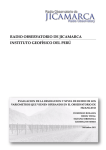
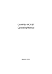
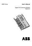
EX – 9940
8 Channel Relay Actuator
PC/104 Module
OPERATING GUIDE
CHECK LIST
Before getting started, check if your EX-9940/EX-9940-16 8 Ch. Relay Actuator
PC/104 Module package includes the following items:
z
z
z
z
EX-9940/EX-9940 – 16 board
Screw 3mm(x 4)
Bronze stick 6mm(x 4)
EX-9940 user’s manual
If anything missing, please contact your dealer.
TABLE OF CONTENTS
GENERAL EDSCRIPTION ............................................................................. 1
Features ............................................................................................................ 1
Specifications ................................................................................................... 2
MODULE CONFIGURATION AND INSTALLATION ............................... 4
Location Diagram ............................................................................................ 4
DIP Switch Setting ........................................................................................... 5
Connector Pin Assignments.............................................................................. 7
MODULE INSTALLATION .............................................................................. 9
REGISTER DESCRIPTION ............................................................................. 10
PROGRAMMING................................................................................................. 11
FUNCTION DESCRIPTION ............................................................................. 12
Relay Output .................................................................................................... 12
BLOCK DIAGRAM ........................................................................................... 13
APPENDIX A PCI/PORT MAPPING ............................................................... 14
APPENDIX B PC/104 MECHANICAL SPECIFICATIONS ......................... 15
GENERAL DESCRIPTION
The EX-9940 relay actuator PC/104 module is designed for control applications. It
contains 8 channels electromechanical single-pole double throw relays which can be
set or reset directly by I/O write instructions. Each relay is rate at 1.5A at 125VAC.
The normal open, normal close and common contacts of each relay are brought out
through a 50-pin mating connectors. A LED, adjacent to each relay, lights up when
the relay is activated. The relay is activated when a logic high is written to the
controlling bit.
Features
z 8 single-pole, double-throw relays
z 125VAC/1.5A maximum contact rating
z Isolation upto 1000 Vrms
z NC, NO and COM contacts output
z LED indicators to show activated relays
Specifications
Relay Output
Number of Channels
8
Type
Electromechanical DIP
Relay,Normal Open
Form
DPDT(wired as SPDT)
Contact Rating
Maximum Switching Power
Maximum Switching Voltage
Maximum Switching Current
30W/60VA
125VDC/125VAC
1.5ADC/1.5AAC
Contact Resistance
100mΩmaximum
Indication Mode
Logic “1”=LED Light on and relay
set
Logic “0”=LED Light off and relay
reset
Life Expectancy
10x106 operations (rated)
Operate/Release
8/8ms
Break down Voltage
Coil to contact
Across contact
1500 Vrms
1000Vrms
Power Requirements
+5VDC
+12VDC
200mA typ.
100mA typ.
Physical/Environmental
Dimension
95mm x 90mm
Weight
230g
Operating Temperature Range
0 to 50℃
Storage Temperature Range
- 20 to 70℃
Relative Humidity
0 to 90%, non-condensing
MODULE CONFIGURATION AND INSTALLATION
Location Diagram
Refer to the following location diagram for help locating components needed during
configuration and installation of the EX-9940 module.
50
RELAY
RELAY
RELAY
RELAY
JP1
REGIST-
REGIST-
REGIST-
REGIST-
49
ER
ER
ER
ER
BIT 8
BIT 7
BIT 6
BIT
D8
D6
D6
SW1
RELAY
RELAY
RELAY
RELAY
REGIST-
REGIST-
REGIST-
REGIST-
ER
ER
ER
ER
BIT
4
D4
2
D7
5
BIT
D3
3
BIT
D2
2
BIT
1
D1
1
2
CN2
64
63
1
1
2
39
40
DIP Switch setting
EX-9940 occupies four consecutive I/O port spaces. The first address or base
address is set via a DIP switch labeled SW1. If more than one modules are to be
installed to one PC, each module must be given its own distinct base address. No
more than one module may use the same base address. When you are selecting the
base address, it would be better if you check with APPENDIX A to avoid conflicting
with other installed devices. Valid addresses are from 200 Hex to 3F8 Hex. Following
figure is the default setting where the base address is set to 300 Hex.
BASE ADDRESS WSITCH SETTING
S1
9
1
8
2
7
3
6
4
5
5
4
6
3
7
2
8
O
N
weighting
512
256
128
64
32
16
8
Base Address = 512 + 256 = 768 (Decimal)
=300 (Hexadecimal)
I/O PORT RANGE
HEXADECIMAL
DIP SWITCH POSITION
3
4
5
6
7
A7
A6
A5
A4
A3
0
0
0
0
0
200 – 203
1
A9
1
2
A8
0
204 – 207
1
0
0
0
0
0
0
1
208 – 20B
1
0
0
0
0
0
1
0
20C – 20F
.
.
220 – 223
.
.
*300 – 303
.
.
3F8 – 3FB
1
0
0
0
0
0
1
1
1
1
1
1
1
1
1
0
3FC – 3FF
1
1
1
1
1
1
1
1
0
1
0
1
0
0
1
0
.
.
0
0
0
0 = ON,
1 = OFF
(*) : Factory default setting
0
0
.
.
.
.
.
.
0
0
.
.
.
.
1
.
.
.
.
.
.
8
A2
0
Connector Pin Assignments
All outputs of EX-9940 are brought out through an 50-pin connectors labeled JP1.
The following figure and descriptions give the necessary data for wiring.
JP1:
NAME
PIN
R1COM
R1NC
R1NO
R2COM
R2NC
R2NO
R3COM
R3NC
R3NO
R4COM
R4NC
R4NO
R5COM
R5NC
R5NO
R6COM
R6NC
R6NO
R7COM
R7NC
R7NO
R8COM
R8NC
R8NO
N/C
1
3
5
7
9
11
13
15
17
19
21
23
25
27
29
31
33
35
37
39
41
43
45
47
49
PIN
NAME
2
4
6
8
10
12
14
16
18
20
22
24
26
28
30
32
34
36
38
40
42
44
46
48
50
R1COM
R1NC
R1NO
R2COM
R2NC
R2NO
R3COM
R3NC
R3NO
R4COM
R4NC
R4NO
R5COM
R5NC
R5NO
R6COM
R6NC
R6NO
R7COM
R7NC
R7NO
R8COM
R8NC
R8NO
N/C
JP1 connector pin description
SIGNAL NAME
DESCRIPTION
R1COM – R8COM
The common contact pins of relays 1 through
8.
R1NC – R8NC
The normally close contacts of relays 1
through 8.
R1NO – R8NO
The normally open contacts of relays 1
through 8.
N/C
No connect.
MODULE INSTALLATION
The EX-9940 PC/104 module is shipped with protective electrostatic cover. When
unpacking, touching the module electrostatically shielded packaging with the metal
frame of your computer to discharge the accumulated static electricity prior to
touching the module.
Following description summarizes the procedures for installing the EX-9940:
WARNING !!!
TURN OFF the PC and all accessories connected to the PC whenever installing or
removing any peripheral board including the EX-9940 module.
Installation procedures;
1.Turn off the system power.
2.Unplug all power cords.
3.Remove the case cover if necessary.
4.Remove the top module if it is a non-stackthrough module.
5.Put the EX-9940 module in line with the top present module as described in
APPENDIX B.
6.Install four spacers if necessary.
7.Connect cable if necessary.
8.Crush between the module until inside distance is SPACER’s height (0.6”) Restore
all the screws.
9.Repeat step 6 until all module are set into position.
10.Connect cable to EX- 9940 if necessary.
11.Replace the case cover and connect all the necessary cables.
12.Turn on the system power.
REGISTER DESCRIPTION
The EX-9940 occupies 4 consecutive addresses in I/O address space, but only one
address is used. During installation, properly set Sw1 switch to select the correct base
address.
The following table shows the register configuration:
Base Address + 0
Bit No.
Bit Name
7
R8
6
R7
5
R6
4
R5
3
R4
2
R3
1
R2
0
R1
Only base address +0 is used for 8-bit wide relay output register. This register is a
read/write register for controlling relays. The controlling bit R1 through R8 is
corresponding to the onboard relay 1 through relay 8. To activate a relay, set the
corresponding controlling bit to “1”. To turn off a relay, set the corresponding
controlling bit to “0”
The data written to the register can be read back as a data for comparison and
confirmation purpose. Base address +1, +2, +3 are all reserved.
PROGRAMMING
Programming the EX-9940 is very simple. It can be easily accomplished using direct
I/O instructions of whatever application language. In this section an example in
BASIC is given.
Example
This example shows how to control the eight relays on module.
Assume the base address is 300Hex.
BASE = &H300
out BASE, 0
out BASE, 1
out BASE, &H80
out BASE, &H55
inp (BASE)
’All relays are off
’Only relay 1 is actuated
’Only relay 8 is actuated
’Relay 1,3,5,7 are actuated
’Read back relay status: 55 Hex
FUNCTION DESCRIPTION
Relay Output
Each of the electromechanical relays has three contacts: COM (Common), NO
(Normal Open) and NC (Normally Close). When a 0 is written to the associated
controlling bit, the COM and NC posts make contact. When a 1 is written to the
controlling bit, the COM and NO posts make contact. Refer to REGISTER
DESCRIPTION and PROGRAMMING sections about how to control the relays.
Logic “0”
NC
COM
NO
Each relay of the EX-9940 is equipped with on LED are labeled D1 through D8,
for relay 1 through 0. The LED lights when relay.
B
U
S
P
C
/
1
0
4
LATCH
CKT
&
DECODE
CKT
+12V
+12V
R8NC
R8NO
R8COM
R1NC
R1NO
R1COM
BLOCK DIAGRAM
APPENDIX A
PC I/O PORT MAPPING
I/O PORT ADDRESS RANGE
FUNCTION
000 – 1FF
PC reserved
200 – 20F
Game controller (Joystick)
278 – 27F
Second parallel printer port (LPT2)
2E1
GPIB controller
2F8 – 2FF
Second serial port (COM2)
320 – 32F
Fixed disk (XT)
378 – 37F
Primary parallel printer port (LPT1)
380 – 38F
SDLC communication port
3B0 – 3BF
Monochrome adapter/printer
3C0 – 3CF
EGA, reserved
3D0 – 3DF
Color/graphics adapter
3F0 – 3F7
Floppy disk controller
3F8 – 3FF
Primary serial port (COM1)
APPENDIX B
PC/104 MECHANICAL SPECIFICATIONS
PC/104 General Description
While the PC and PC/AT architectures have become extremely popular in both general
purpose (desktop) and dedicated (non-desktop) applications its use in embedded
microcomputer applications has been limited due to the large size of standard PC and
PC/AT motherboards and expansion cards. PC/104 module can be of two bus types, 8
bit and 16 bit, which correspond to the PC and PC/AT buses, respectively.
Besides bus option, there are stackthrough and non-stackthrough difference. The
stackthrough version provides a self-stacking PC bus. It can be placed any where in a
multi-module stack. The non-stackthrough version offers minimum thickness, by
omitting bus stackthrough pins. It must be positioned at one end of a stack.
For ocnvenience . the EX-9940 is equipped with stackthrough version only. (NOTE :
For safety, you are suggested to cut bus stackthrough pins of the last module on
condition; that you are sure you won’t add/plug any module to the module stack in the
future.)
The following sections provide the mechanical and electrical specification for a compact
version of the PC/AT bus, optimized for the unique requirements of embedded systems
applications. The specification is herein referred to as “PC/104”.