1
"Executive" PCU
for Scanreco G4 systems
SERVICE MANUAL
SUMMARY
1.
Characteristics ................................................................................................... 2
1.1.
2.
3.
Switching on the transmitter.............................................................................. 2
Description of operation modes ........................................................................ 3
2.1.
Operation mode (1) ............................................................................................. 3
2.2.
Operation mode (2) ............................................................................................. 3
2.3.
Test mode............................................................................................................. 4
2.4.
Assign mode......................................................................................................... 4
2.5.
Calibration mode ................................................................................................ 4
Code recognition procedure.............................................................................. 9
NOTE: This Service Manual is addressed to the radio remote control installer as integration
of the User Manual that follows each system.
-1-
1.
Characteristics
The Executive Portable Control Unit (PCU) of the Scanreco G4 remote control can be
switched on and function in different operation modes described hereunder.
1.1. Switching on the transmitter
OPERATION mode
This is the usual mode for which the radio control was designed.
Rotate the emergency stop button clockwise to release it.
until the red LED light on the right comes on.
Press the pushbutton marked
The transmitter switches on in “OPERATION” mode.
A more detailed explanation of the function in this operation mode is contained in Chapter 2.
TEST mode
This is the mode in which to verify the proper functioning of the levers and pushbuttons.
Rotate the emergency stop button clockwise to release it.
Switch the transmitter on as usual and immediately after, repeatedly press the switchon pushbutton 10 times (until the red LED light on the right switches off).
The transmitter is now on “TEST” mode.
A more detailed explanation of the function in this operation mode is contained in Chapter 2.
ASSIGN mode
This is the mode to use so that the receiver will recognize the Portable Control Unit (PCU).
This is done, usually, when replacing one of the two parts.
Rotate the emergency stop button clockwise to release it.
Press the switch on pushbutton and keep pressed for about 4-5 seconds until a short
BEEP is heard.
The transmitter is now in ASSIGN mode and you can release the pushbutton.
A more detailed explanation of the function in this operation mode is contained in Chapter 2.
CALIBRATION mode
This is the mode to use for adjusting the speed of the operations, the inversion of the functions
and the type of ON/OFF outputs (latched or non latched).
Rotate the emergency stop button clockwise to release it.
Switch the transmitter on as usual and, immediately after, quickly turn the “Fn” switch
to the right repeatedly for 10 times until you hear a short BEEP.Both LED lights will
remain off.
The transmitter is now on “CALIBRATION” mode
A more detailed explanation of the function in this operation mode is contained in Chapter 2.
-2-
2. Description of operation modes
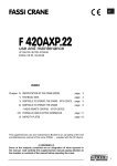
2.1. Operation mode (1)
1A
2A
3A
4A
1B
2B
3B
4B
mode 1
Fn
In this mode (the “Fn” switch is released) the levers from 1 to 4 (from left to right)
control the first 4 proportional outputs.
pushbutton controls OUT2 (Horn).
The
By moving switch “Fn” to the left and keeping it in this position you enter
OPERATION MODE 2.
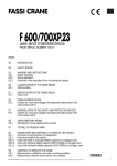
2.2. Operation mode (2)
5A
6A
5B
6B
RPM+ Start
OUT1
OUT2
Clacson
OUT3
mode 2
OUT4
Stop
Fn
By moving switch “Fn” to the left and keeping it in this position you enter OPERATION
MODE 2.
Release the “Fn” switch to return to OPERATION MODE 1.
In this mode the first two levers from the left control proportional outputs 5 and 6 (in
some systems one or both controls can be disabled).
By pushing forward the 3rd lever from the left you control the on/off OUT1 output.
(RPM+).
By pulling backward the 3rd lever from the left you control the on/off OUT2 output
(Horn) - (this is the same as the
pushbutton control).
By pushing forward the 4th lever from the left you control the on/off OUT3 output
(Start)
By pulling backward the 4th lever from the left you control the on/off OUT4 output
(Stop)
WARNING: the above describes the association of proportional functions and on/off outputs relating to the
standard FABER-COM radio controls. Some special systems could have functions associated in a different
manner. Consult the specific diagram attached to the system for a correct correspondence.
ON/OFF outputs working
If the on/off output is configured as non latched, the output switches off releasing of the lever.
If the on/off output is configured as latched, every activation of the lever will cause the output
status to change (from OFF to ON and vice versa).
The working type of each on/off output can be modified in CALIBRATION mode.
-3-
2.3. Test mode
When in TEST mode both LED lights are off.
Every time the “Fn” switch is activated or released, a short BEEP should be heard. If
no acoustic signal is heard, it means that there is a malfunction or that the electronic
card inside the transmitter is faulty.
Every time a control lever is activated, an acoustic signal should be heard which
increases in frequency concurrently with the increase of the lever’s angle. When the
lever reaches its maximum angle, the acoustic signal should be long.
If no acoustic signal is obtained when moving the lever, it means that it is faulty or
else that the contacts are faulty or that the PCU electronic card is faulty.
When the transmitter is in this mode the receiver does not respond to the controls.
2.4. Assign mode
When the PCU is switched on in ASSIGN MODE, it transmits a code setting message
to the receiver and the transmission will continue until it is switched off.
During this period of time, the receiver must be switched on with the special plug
(called "pairing plug") screwed on to the connector.
See chapter 3 for a complete description of the code setting procedure.
2.5. Calibration mode
In this mode you can adjust the speed of the functions, the inversion of the functions and
the type of ON/OFF outputs (latched or non latched).
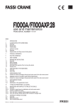
AVAILABLE CONTROLS
The controls to use in calibration mode are represented in the diagram below.
Emergency stop button
Switch on
and advancement
of programming steps
“Fn” calibration
parameters adjustment switch
decreases
increases
Left LED light
green/red
Right LED light
green/red
To chose the function which you want to program, you must also activate the proportional
levers.
-4-
CALIBRATION PROCEDURE
As soon as you enter the CALIBRATION mode, both LED lights will be off and the PCU
will BEEP every 4 seconds.
Press
pushbutton once to move to the first programming step.
pushbutton is used to advance from one calibration step to another: every time
The
you press the
pushbutton you move to the following step.
The programming step in which you are is identifiable by the number of BEEPs from the
PCU and the status of the red LED light on the right.
Once the programming is finished, to exit programming mode and store the new
configuration, switch the PCU off by pressing the emergency stop button.
Use the "Fn" switch to change the value of the parameter that you are programming.
While programming it is useful to open the receiver’s lid so you can read the parameter
you are changing on the display.
PROGRAMMING STEPS (summary table)
1
left
LED
green
right
LED
x
Set time for PCU automatic switch off
2
2
green
green
Chose transmission radio channel
3
3
x
x
Not used
4-A
4
x
x
Adjust minimum speed for functions 1 to 4
4-B
4
x
red
Adjust minimum speed for functions5 and 6
5-A
5
x
x
5-B
5
x
red
6
6
x
x
Choose type of function on/off outputs from OUT1 to OUT4
7
7
x
x
Choose type of function on/off outputs OUT5 and OUT6
8-A
8
x
x
Invert direction for functions from 1 to 4
8-B
8
x
red
Step
n° beeps
1
Description
Adjust maximum speed for functions from 1 to 4
Adjust maximum speed for functions 5 and 6
Invert direction for functions 5 and 6
NB: Steps 4, 5 and 8 are divided into two parts:
- the first part (-A) with the LED light on the right OFF (relative to functions from 1 to 4)
- the second part (-B) with the LED light on the right ON (relative to functions 5 and 6)
In these special steps, when you press the
pushbutton, the programming step advances
from part -A to part -B of the same step (part -B is identifiable by the LED light on the
right being on), then proceed to the next step.
When you reach the last step (8-B) by pressing the
pushbutton you will return to the
first programming step.
The following page describes the programming steps in further detail.
-5-
DESCRIPTION OF THE PROGRAMMING STEPS
Step 1 – set PCU automatic switch off time
The PCU BEEPs every 4 seconds.
The green LED light on the left can be in the following configurations:
- Always on = automatic switch off disabled
- 1 flash = automatic switch off after 2 minutes
- 2 flashes = automatic switch off after 5 minutes (default)
- 3 flashes = automatic switch off after 10 minutes
Step 2 – set working frequency
The PCU BEEPs twice with a pause in between.
The radio transmission channel can be set either in variable or fixed mode.
The two LED lights on the left indicate, with their status, the tens and unit digits of the
radio transmission channel respectively, according to the following table:
left green LED light
Right green LED light
0 = LED always on
10 = 1 flash
20 = 2 flashes
30 = 3 flashes
40 = 4 flashes
50 = 5 flashes
60 = 6 flashes
70 = 7 flashes
80 = 8 flashes
90 = 9 flashes
0 = LED always on
1 = 1 flash
2 = 2 flashes
3 = 3 flashes
4 = 4 flashes
5 = 5 flashes
6 = 6 flashes
7 = 7 flashes
8 = 8 flashes
9 = 9 flashes
By using the "Fn" switch it is possible to modify the transmission channel in the following
manner:
Every time the “Fn” switch is switched to the left, the tens digits are increased by one in a
circular manner (when it reaches 9 it goes back to zero).
Every time the “Fn” switch is switched to the right, the unit digits are increased by one in
a circular manner (when it reaches 9 it goes back to zero).
0x
1x
2x
3x
4x
5x
6x
7x
8x
9x
TENS
Fn
UNIT S
XX
Fn
x0
x1
x2
x3
x4
x5
x6
x7
x8
x9
By setting the channel on 00 (both Led lights always on), the transmitter works on
variable frequency (standard configuration). The channel number can be set from 01 to 66.
If the working channel is changed the Code Recognition procedure must be repeated (see chap. 3)
-6-
Step 3 – setting the type of transmitter
The PCU BEEPs three times with a pause between each beep.
This programming step does not apply to this type of PCU.
Adjusting the "START" parameter
Step 4-A – adjusting the initial speed for functions from 1 to 4
The PCU BEEPs four times with a pause between each beep.
Red LED light on the right is off.
Step 4-B – adjusting the initial speed for functions 5 and 6
The PCU BEEPs four times with a pause between each beep.
Red LED light on the right is on.
-
Move the operating lever that you want to adjust just outside the dead band (you need
to switch on the red DV LED light on the receiver) and, keeping the lever in this
position, increase or decrease the operating speed by switching the “Fn” switch to the
right or to the left. By keeping the switch in the same position the speed will not
change.
Adjusting the "STOP" parameter
Step 5-A – adjusting the maximum speed for functions 1 to 4
The PCU BEEPs five times with a pause between each beep.
The red LED light on the right is off.
Step 5-B– adjusting the maximum speed for functions 5 and 6
The PCU BEEPs five times with a pause between each beep.
The red LED light on the right is on.
-
Move the operating lever to the limit and, keeping the lever in this position, increase
or decrease the speed by switching the “Fn” switch to the right or to the left. By
keeping the switch enabled the speed won’t change.
Step 6 – configuration of ON/OFF outputs from OUT1 to OUT4
The PCU BEEPs six times with a pause between each beep.
Considering the levers numbered from left to right:
Push or pull the 1st lever to configure output OUT1
Push or pull the 2nd lever to configure output OUT2
Push or pull the 3rd lever to configure output OUT3
Push or pull the 4th lever to configure output OUT4
Keeping the lever engaged switch the “Fn” switch either to the left or to the right to
change function mode form latched to non latched and vice versa.
-7-
Step 7 – configuration of ON/OFF outputs OUT5 and OUT6
The PCU BEEPs six times with a pause between each beep.
Considering the levers numbered from left to right:
Push or pull the 1st lever to configure output OUT5
Push or pull the 2nd lever to configure output OUT6
Keeping the lever engaged, switch the “Fn” switch just once to the right or to the left to
change function mode from latched to non latched and vice versa.
Step 8-A – invert direction of proportional functions from 1 to 4
The PCU BEEPs seven times with a pause between each beep.
The red LED light on the right is off.
Step 8-B – invert direction of proportional functions 5 and 6
The PCU BEEPs eight times with a pause between each beep.
The red LED light on the right is on.
Engage the lever of the function you want to invert the direction and, keeping the lever in
this position:
-
Briefly switch the “Fn” switch to the left to set to normal direction
(side A pushing the lever forward – side B pulling the lever backward), or
-
Briefly switch the “Fn” switch to the right to set to inverted direction
(side A pulling the lever backward – side B pushing the lever forward).
-8-
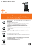
3. Code recognition procedure
This procedure must be followed to pair the receiver with the transmitter in case of
replacement of one of the two components.
1) Start with receiver and transmitter both switched off.
2) Unscrew the protection cap and screw on the special yellow
plug provided.
(Pairing Plug p/n: 48118)
3) Press the switch on pushbutton on the PCU and
keep pressed for about 4-5 seconds until you
hear a short BEEP.
The transmitter is now on ASSIGN mode and
you can release the pushbutton.
4) Switch on the receiver on REMOTE (the transmitter must be close to the receiver: less
than 3 meters apart)
5) Wait for about 5 seconds.
6) Switch off the transmitter.
7) Switch off the receiver.
8) Unscrew the yellow plug (PAIRING PLUG) and place in a safe place to use again. If
you switch ON again the receiver with the Pairing Plug installed, the transmitter code id
erased and the procedure must be repeated.
9) Screw the protection black cap on the connector of the receiver.
When the system is switched on again the receiver will recognize the transmitter and will
function normally ("1H" will appear on the display inside the receiver and led STATUS
green, on).
Repeat the procedure from the beginning in case of malfunction.
-9-