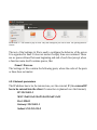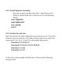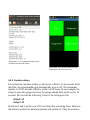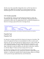
1
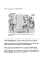
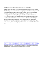
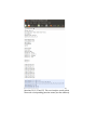
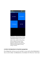
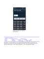
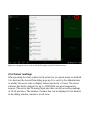
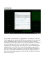
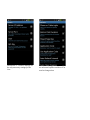
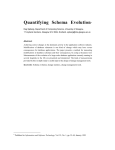
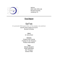
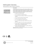
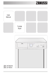
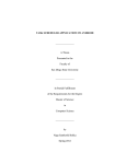
Home Ctrl 28
User Manual
Table of Contents
1. The funny and true introduction.............................................................................................................3
2. Features..................................................................................................................................................5
2.1 Is it safe?..........................................................................................................................................5
2.2 Three Network profiles for each client ...........................................................................................7
2.3 The number of functions that can be controlled..............................................................................8
2.4 First introduction to function properties........................................................................................10
2.5 Advanced features.........................................................................................................................14
2.5.1 Time and Alarm functions.....................................................................................................14
2.5.2 Server readings......................................................................................................................16
2.5.3 Pro-Tab..................................................................................................................................17
2.6 The difference between Admin Users A-F and “Normal” Users 0-9............................................18
2.5.3 Customization of server software.........................................................................................19
3. What the User has to know..................................................................................................................20
4. What the Administrator has to know....................................................................................................22
4.1 Hardware setup..............................................................................................................................22
4.1.1 Teal Time Clock.....................................................................................................................23
4.1.2 Temperature sensors..............................................................................................................24
4.1.3 Relay cards.............................................................................................................................25
4.1.4 Activity indicator LED..........................................................................................................26
4.2 Settings file....................................................................................................................................26
4.2.1 Network parameters...............................................................................................................27
4.2.2. The AES key(s) for the User(s) ...........................................................................................28
4.2.3. Functions for each User........................................................................................................28
4.2...................................................................................................................................................29
4.2.4. Function names.....................................................................................................................29
4.2.5. Function delays.....................................................................................................................30
4.2.6. Function properties...............................................................................................................31
4.2.7. User PIN codes.....................................................................................................................32
4.2.8. Update parameter (optional) ................................................................................................33
1. The funny and true introduction
Illustration 1: An electrical interference as stating point for building a home
control system
A view days before Christmas 2011, I was cooking and once again, this tiny,
stylish touch-dimmer light went on together with the cooking hood I just
turned on. The difference on this day was I decided to leave it on for the
evening- for some additional Christmas atmosphere. I decided that, for this
evening, this behavior was planned. It is home automation.
Arising from this, some questions came to my mind: Can I make it more
predictable? Increase the range? Use a second hood to switch the light off,
would I have room? Can this be used for other lights? Can one bring this to
marked? Some days later I decided for a completely different approach: An
Android and Arduino based home control system.
Eight Control Arduino was the first release and can be seen as an entry level
internet based home control system. Home Ctrl 28 in contrast is an advanced
multi-user system, offering server-sided user right administration, up to 16
different user keys, 28 control functions, real time clock functionality,
multiple profiles and more.
Home Ctrl 28 operation is easy and error-free for the USer. In this manual the
“User” is a person using an Android device to control functions on the server.
The “Administrator” is the person setting up the server (even if the
Administrator is often also a User).
The Home Ctrl 28 mobile application and server software is the result from
experience with Eight Control, the additional features suggested by users, and
my own expectations for this product. I thank all the users who helped with
feedback and suggestions on Eight Control.
A Home Ctrl 28 system not only offers the possibility to control devices at
home over the Internet, at a price well below comparable systems. It also is a
fantastic learning tool for new Arduino users, and offers the possibility to add
and modify the server program for advanced users to fit almost everybodys
needs.
2. Features
This section contains general information on Home Ctrl 28. It is designed to
get some basic information about the system. You do not have to
understand everything here, it will be explained in detail in the next
chapter.
2.1 Is it safe?
The transmission between server and clients is secured by AES128. That
means the keys can have up to 16 characters (128 bits). The server supports
16 different AES keys, so 16 users (named A to F and 0 to 9) can have a
different key. There is also a measure to prevent a third party from “stealing”
commands sent between clients and server: Both sides “pack” random
numbers into their data. If on the returning signal this random numbers have
changed, the commands are ignored. In summary, the transmission is
comparatively safe. Much safer than a physical key. The whole mobile
application can additionally be protected by a pin code. The image below
shows how AES keys for 5 users are set on the server configuration file. Each
user enters his AES key into his mobile application at configuration.
Illustration 2: The blue mark shows
AES keys set for Users A, B, C, 5 and
8. These users have to enter the same
key into their Android device.
Illustration 3: The user can protect the app with a pin code.
2.2 Three Network profiles for each client
Each Network Profile can be configured to connect to one server. As an
example, a user can connect with his Android phone to 3 different servers: To
a server in his home, to one in his weekend house, and to a third server in his
company. Each profile has a name containing the color (Green Fruit, Blue
Moon, Orange Star), and function buttons of the same color. A user can
choose which profile (color) he likes best for which server. Once a profile is
selected, four network settings for this profile can be made (Server IP
Address, Server Port, User and AES Key). These settings are of course
remembered for this profile.
Illustration 4: Profile selector. Each Profile can be
used to connect to a different server.
2.3 The number of functions that can be controlled
Home Ctrl 28 can control a total of 28 server sided functions, which means
that 28 relays can be connected to the output pins of the Arduino Mega board.
Every user can control up to 16 functions of these 28. So Users can share
functions, or can be the only one to be able to switch a function.
Looking at the same settings file again, User A was allocated functions
1,2,3,10,11,12. User C was allocated more than 16 functions, which is not
possible as the limit is 16 per user - the last two (Functions 27 and 28) are
ignored by the system in this case. On the Android device, the allocated
functions show up with their names, if names have been set (see later). If no
name was set, the function displays as “Function” and number, like “Function
12”.
Illustration 5: The Pin table. It shows which function (number 1 to 28) switches which output pin on
the Arduino Mega. All of these pins are located on the right side of the board.
Illustration 6: The blue area shows that User 8 can use
functions 20,21,22 and 23. The user interface on the phone
shows the corresponding function names (not the numbers).
Illustration 7: The device of User 8 shows
the 4 functions with their names. Function
20 (top left) was named "20: None" by the
administrator. This given name seems to
make no sense, but later it will be shown
that every function can have certain
properties. The names None, Confirm,
Random and PIN are given in this case to
demonstrate these properties (security
dialogs, see below).
2.4 First introduction to function properties
First things first: As User, you do not have to care at all- as the Administrator
has to care for them. As Administrator of an Home Ctrl 28 server: You do not
have to set up Properties. For the simple scenario, one press of the function
button switches the function (relay) on, another press switches the function
off: No function properties are needed.
1. But if a function triggers a door opener? The User presses the button for
“Door” (function 2). The relay for function 2 closes for 3 seconds (then
switches off, like specified in the Settings file (“Delay2=3”). But the
button on the user interface (Android phone) would still show “on”
because there was no reconnection to the server. This is confusing. The
function properties can bring the Android button back to off-state
automatically after 4 or 8 seconds.
2. You have a very sensitive function, like opening the door to your
company. Would you like your employees (Users) to play around with
their phones and accidentally open the door? If no, the function
properties can require the user to enter a PIN code, a client-generated
random number, or at least a confirm dialog before the Users can open
the door.
3. You want to switch on and off a fridge in your second home (to have
some cold beer when you arrive). How do you tell your server to
remember the on/off state of the fridge, even in case the power drops
out? You can use the function properties and set the SaveState property.
Function properties are set up on the server Settings.txt file. They look like
below- where Properties1 sets the Properties for Function 1:
Properties1=nns
• The 1st character can be y (yes) or n(no). It determines if or not the
server remembers the state of a function if the power drops out, or if the
server is restarted (if set to “y” the on/off state is being written to an
EEPROM and restored). If no function property is set for a function,
this function is always off after restart or power down.
•
The second character can be n(none), c(confirm), r(random) or p(PIN).
It determines what a user has to do to switch this function. If “n”, the
User can just press the button and switch the function. If “c”, a confirm
dialog prompts the User to confirm the action. If “r”, the User is
confronted with a dialog that needs him to enter a displayed 4digit
random number-an absolute measure against accidentally executing a
function. The correctness of the entered number is checked on the
client. If “p” is set, the User has to enter a PIN code into a pop-up
dialog. The correctness of the PIN is checked on the server. An
measure to exclude that the wrong user executes the function. A PIN
code can be set for each user (not for each function!)
• The 3rd character can be n(none), s(short) or l(long). If set to none, the
User button on the phone/tablet has the usual on-off behavior. If “s” is
set, the client button automatically goes to off-state after 4 seconds. And
if “l” is selected, it goes to off after 8 seconds.
That is the whole magic of the function properties, that always consist of 3
characters! A full table of the options will be given in the next sections.
Below is a screenshot of the random number dialog that appears if the second
character of a function property is set to “r”.
Illustration 8: Function Properties
for this function set to "r" for the
2nd character
Illustration 9: Function Properties: Three characters determine the behavior of a function. The
Properties are set on the server, but transmitted to the clients. They can be visualized on the user
interface when the option “Show Function Properties” is set in the application settings.
2.5 Advanced features
Until now it was explained that Home Ctrl 28 can control 28 functions (micro
controller pins which can be connected to relays). From user feedback on
Eight Control, I was aware that there is a need for timer functions, as well as
the ability to control additional parameters on the server, as well as improved
flexibility in displaying readings (data) from the server.
2.5.1 Time and Alarm functions
Illustration 10: The time/Alarm dialog is started by pressing the clock icon on the Title Bar (or in the
option menu). In this example, a weekday alarm is set to 7:17 am.
A user can do the following things:
• Set up an daily alarm, weekday or weekend alarm, or an alarm that goes
off only once. The alarm will turn pin 6 high on the Arduino board for
300 seconds (or until disabled by pressing the “Stop this Alarm”
button).
• Set up a daily on and off time 1. For the time interval between the 2
times, pin 7 of the Arduino board will be high (otherwise low). Both,
Timer1 on and Time1 off have to be on!
• Set up a daily on and off time 2. For the time interval between the 2
times, pin 8 of the Arduino board will be high (otherwise low). Both,
Timer2 on and Time2 off have to be on!
• Sync the RTC (real time clock) of the server to the current time and
date of the mobile device. Only Users A to F have the “Sync Time”
button available.
Illustration 11: This dialog is displayed after pressing "Set Alarms" or "Sync Time" from the previous
dialog. It displays server time/date from the server RTC, and the alarm status. Red entries are in the on
state. The "Edit" button takes the user back to the previous dialog.
Illustration 12: The Server Data dialog displays all values configured on the server. It would not
difficult to change the server code to selectively display values to individual users.
2.5.2 Server readings
When pressing the chart symbol in the action bar (or option menu on Android
2.xx devices) the Server Data dialog pops up. It is easy for the Administrator
to modify the server code to display values selectively to Users. The server
software has built in support for up to 4 DS18S20 one-wire temperature
sensors. The server has 16 analog input pins that can deliver analog readings
of 10 bit precision. The number of values that can be displayed is not limited,
as the dialog window contains a scroll-view.
2.5.3 Pro-Tab
Illustration 13: The equalize symbol in the action bar (or option menu) brings up this dialog.
“Pro” stands for “Professional” or “Programmer”. The values set in the ProTab by toggle-buttons, sliders and EditTexts are transmitted to the server and
stored in EEPROMs (and are therefore accessible like global variables).
They are however not used on the server in any way, and have no connection
to the 28 output pins. The idea is to use the values to for example set up a
temperature for a heating system. It is fully up to the server Administrator to
implement this in code. Pro-Tab is in an early development stage, and the
next step could be to make it possible to constrain the values transmitted as
bytes (i.e to for example constrain 0 to 255 to 18 to 25 degrees, and show
these values and their meaning on the UI). Pro-Tab is available to Users A-F,
and not to Users 0-9.
2.6 The difference between Admin Users A-F and “Normal” Users
0-9
When the User sets up the mobile account (consisting of IP Adress, Server
Port, User and AES key) he notices that the User can be Admin A to F , and
User 1 to 9 and 0. There are only a few differences. Admin A to F accounts
include the possibility to sync server date/time to the phone time, and can
display the Pro-Tab. “Normal Users 1 to 9 can not do theses 2 things.
However, this behavior could be changed by the server administrator
(modification of server software).
Illustration 14: The setup page for the
user. Only if the correct user is
entered, the server can correlate it to
the correct AES key.
2.5.3 Customization of server software
From the 256 KB of Flash Memory that the Arduino Mega has, less then 25%
are used. There are also a couple of free I/O pins available (the reason for
Home Ctrl 28 to “only” use 28 output pins). There is built in support for up
to four DS18S20 temperature sensors, and if connected, their temperature
reading can be returned from a simple function call. Pro-Tab makes it
possible to transmit any value from a phone to the server.
It is obvious that the same controller board can be used to do a lot of
additional things, much more than is currently implemented.
From Eight Control, some customization examples users suggested were:
Switch an additional output pin according to temperature. Transmit a
temperature value to and from the server. Time-control output pins. Have an
all-off (“macro”) button on the user interface.
All these wishes are too specific to be included a priori. It is a “feature” of
Home Ctrl 28 to have open source server code and therefore be able to
customize the application. I will not be able to do this for everyone, but will
help as good as possible in getting the idea how to do this, and where to place
the additional code in the server software.
3. What the User has to know
The user first loads the profile selector from the option menu, and selects a
profile he wants to use (usually based on his color preference). Then he sets
IP address, Port number, User and AES key from the option menu → Settings
→ Network.
Returning from the settings menu, the application automatically connects to
the server, transmits the function names and displays the button states.
There are additional setings under option menu → Settings → Application.
They are explained in detail below, but do not need to be touched at all.
• Phone or tablet style: Changes the arrangement of buttons to be
displayed in one row (phone) or 2/4 rows (depending on tablet style
orientation).
• Button Click Duration: Some users want to avoid to accidentally press a
function button. If selected, a long press is needed to switch a function.
• Show properties: Function properties set on the server can be displayed
on (tablet style) or beside (phone style) a button. The default property is
“- - -” which means no SaveState, no key protection and no auto-off is
set.
• Application code: set a protecion code for the application. This way you
can borrow your phone to somebody without having to fear he will use
Home Ctrl 28.
• Use Application Code: Enable the Application Code. If the user forgets
the code, it is necessary to completely deinstall and reinstall the
application, and re-enter connection data.
• Auto-refresh interval: If set to other than “No Auto Refresh” the device
will periodically connects to the server. It will not switch to standby and
therefore an external power supply is recommended.
• Auto-Close closes the application some seconds after switching a
function.
Illustration 15: Network settings are
the only necessary settings for the
User
Illustration 16: Application settings
are advanced options and there is no
need to change them
4. What the Administrator has to know
4.1 Hardware setup
Home Ctrl 28 needs an Arduino Mega board. The Arduino Mega (or
compatible) board as well as an Arduino Ethernet Shield are the basic
requirements. Alternatively an EtherMega board can be used, which houses
the Micro Controller, Ethernet port and card reader on one board. For how to
program the Arduino and connect relays I will refer to the Arduino Eight
Control website. The only difference to mention is to select the correct board
in the Arduino IDE, and the different output pins to connect to relays.
Illustration 17: The Pin table. It shows which function (number 1 to 28) switches which output pin on
the Arduino Mega. All of these pins are located on the right side of the board.
Optional hardware is a DS 1307 based real time clock module, one to four
DS18S20 temperature sensors and a small active buzzer for the alarm.
Illustration 15: EtherMega 2560 board running Home Ctrl 28 software.
Connected is a RTC module (SDA on pin 20, SCL on pin 21) and an active buzzer
(pin 6). Even without any relays connected, this already makes up a network
controlled alarm clock for daily, weekday, weekend and single alarm! A small
battery on the RTC board remembers the time, the alarm times are stored in
EEPROM memory.
4.1.1 Teal Time Clock
A DS 1307 based real time clock module is readily available for the Arduino
platform. It has a size similar to a stamp, and a small battery which keeps the
time up and running for several years. There are several RTC software libraries
available for the Arduino platform. In most code examples, the compile time
(time when the project is sent to the Arduino) is used to set the clock. Other
examples use hardware buttons and LCD shields. The RTC uses the I2C bus
system. Home Ctrl 28 takes the approach to be able to synchronize the time to
the time of the Android device. This is a procedure actively performed by Admin
users A to F, from the Time dialog. Users 0 to 9 are not able to perform this task
(although this can be changed in the server code). If the time or any alarm time
is changed, the server time is displayed in the dialog.
If no RTC is connected on the server, the time can of course not be correctly
displayed. Apart from that, the server works normally. Therefore there is no need
to connect a RTC if the time and alarm options are not needed.
Four wires have to soldered to the RTC. I recommend the usual and
inexpensive flexible jumper wires, and cut off their edges on the battery side of
the RTC. Then +5 Volts and ground can be connected easily to the socket of the
Ethernet Shield, or Arduino Mega. The SDA connector has to be connected to
pin 20, SLC to pin 21. The RTC can be glued to the Arduino board with a
double-sided gluing strip (see image above).
Illustration 18: A RTC module.
Flexible jumper wires can be
soldered to the board. This is the
only situation where soldering is
needed in the project. The SQW pin
is not needed in this project. There is
a link to the board on sparkfun:
https://www.sparkfun.com/products/
99
4.1.2 Temperature sensors
Of course many temperature sensors can be connected to Arduino boards. I
choose the DS18S20 because it is well supported and often used in forums, so
that example code is available. Also, as this sensor transmits digital signals
instead of temperature-proportional voltage, it should be less dependent on
cable properties and length. The sensors look like transistors, but they are micro
controllers. They have an electronic ID and this way it is possible to have more
sensors on the same bus system, in a parallel order. I used a small breadboard
to wire up everything. There is a good image on
http://bildr.org/2011/07/ds18b20-arduino/ that displays how to connect the
DS18S20.
Illustration 19: Image displays connection of DS18S20. The black wire is going to
Arduino ground, the red one to +5 Volts. The orange one is connected to pin 2.
The resistor has 4.7 kilo-ohms (yellow, violet, red and tolerance)
4.1.3 Relay cards
There a many products on the marked that can be used. It has to me mentioned that the
Arduino can not directly drive a relay. Suitable relay cards contain components to avoid
this current overload, and therefore the cards require a power supply. Below is an
example of the ones I use. There are also SSD relays available, that do not contain
moving parts. Usually their current load is lower, but sufficient for many purposes.
Illustration 20: A typical relay card that can be used for
Arduino. A card like this should cost below 10 Euros. A
power supply has to be connected. Take care not to take
this power supply from the Arduino pins, their current is
limited.
4.1.4 Activity indicator LED
A simple LED can be connected to pin 9 (via a resistor of about 1200 Ohms).
The LED will blink every second, after the server has read the data stored on
the SD card successfully.
4.2 Settings file
The Ethernet Shield contains a card reader for a micro SD card. On this card,
the Settings.txt file has to be contained. If the server is installed somewhere,
and the server configuration has to be changed, the card can simply be taken
to a PC for editing the file, and then placed back into the server. The server
has then to be restarted by pressing the reset button (or pulling the power
cord out for a second). The SD card can only contain one Settings.txt file (but
may contain other data as well).
Illustration 21: The content of my SD card. Only the Settings.txt file will be read. The spelling must be
correct.
The text of the Settings.txt file is used to configure the behavior of the server.
It is organized in lines. It does not matter if empty lines are contained. There
are no spaces allowed between beginning and end of each line (except when
a function name itself contains spaces, like:
Name1=Press me
The Settings.txt file contains the following parts, where the order of the parts
or lines does not matter:
4.2.1 Network parameters
The IP address has to be the internal one, not the external IP (the external IP
has to be entered into the client if connection is planned over the Internet).
IP=192.168.1.5
MAC=0x60-0xA3-0xD5-0x00-0x6F-0x22
Port=50044
Gateway=192.168.1.1
Subnet=255.255.255.0
4.2.2. The AES key(s) for the User(s)
Also here no spaces on either side of the = sign. Here keys for
Admin A, Admin B and User 5 and 8 are set. Use the following
format:
KeyA=30ghjzt45d
KeyB=4dfdhuiG887
Key5=AbCdEf
Key8=8
4.2.3. Functions for each User
Next, the functions that each configured user can execute, are set. User A has
6 buttons on his user interface. According to the pin table, he can switch the
output pins 22, 23, 24, 31, 32 and 33 on the Arduino Mega board.
FunctionsA=1,2,3,10,11,12
FunctionsB=1,2,3,10,11,12,13,17,18,19,22
Functions5=1,2,3,10
Functions8=1,2,3,11
At this point a small example should be done: I have used the following
Settings.txt file:
4.2.
Illustration 23: Example of a Settings.txt file. The keys are not
save, but OK for testing. User A can expect to have 4 buttons on
the UI.
Illustration 22: The result is like
expected if Network Settings for User
A are entered correctly. Functions
have their default name, as none was
set yet. User A decided to use the
Green Fruit profile.
4.2.4. Function names
In the example above, the functions on the User Interface show their default
names. It is possible to use more meaningful names instead. Again this is
done with the Settings.txt file.
Illustration 25: The updated Settings.txt file
includes now function names.
Illustration 24: Function names are now
displayed as set up on the server
4.2.5. Function delays
Every function can have a delay on the server, which is set in seconds. After
this time, the corresponding pin automatically goes to off. The maximum
number is 32767 seconds, which is a little over 9 hours. In our example, the
relays to open the garage and close the garage should only switch on for 10
seconds. We can add the following 2 lines to the Settings.txt file:
Delay2=10
Delay3=10
Functions 2 and 3 switch now off 10 seconds after executing them. However,
the buttons on the User Interface (phone) will remain on. They do not know
that the server has meanwhile changed the state to off. (If any button is
pressed or the application is reopened, of course all button states are
refreshed again). To solve this issue, function Properties can be used.
4.2.6. Function properties
We would like the Garage open and Garage down button to return off
automatically after 4 seconds. Also, the opening of the garage should be
protected by a PIN code. The Administrator has to set function Properties for
function 2 (Garage open) and function 3 (Garage down).
Illustration 26: Function Properties: Three characters determine the behavior of a function.
Properties2=npl
Properties3=nnl
For function 2 (Garage open) the first character (n) means no SaveState. The
status of the pin does not have to be remembered. So After a restart it will
always be off. The second character (p) requires the user to enter a PIN code
when opening the garage. We will set up a PIN (which is specific to a user,
not to a function) in the next chapter. The 3rd character (l) stands for long
delay. The button on the user interface (not the relay on the server, which is
set with the Delay2=10 line!) will auto-release after 8 seconds.
For function 3 (Garage close) the 1st and 3rd character are the same.
However, the 2nd character, none, means that no kind of confirm dialog (pin,
random, or confirm) are required when closing the garage. Below are images
of all 3 protection types (determined by second character):
Illustration 27: Confirm dialog
Illustration 28: Random dialog
Illustration 29: PIN dialog
4.2.7. User PIN codes
The PIN codes are specific for each User. One PIN can be set for each of the
16 Users. For every function that is PIN protected, all users has to enter their
individual PIN code. There is no way to have different PINs for one user.
The PIN can range from 1 to 32767. Preceding zeros will be ignored. If the
PIN is outside of the mentioned range, malfunctions can occur. To set a PIN
for User A and B, enter:
PINA=1234
PINB=3333
This is our final Settings.txt file. I also passed a PIN to User B, even if this
user does not have a PIN-protected function by now.
Please take a look at the last line: Update=3. This line is optional. Read about
the meaning in the next paragraph.
Illustration 30: Remember that the PIN
must be 1 to 32767. The last line is the
version of the Settings.txt file. Changing it
causes all clients to reload function names
and function properties.
4.2.8. Update parameter (optional)
In the last Settings.txt file, the last line was “Update=3”. This represents the
version of the file. Whenever this number is changed, all connecting clients
are forced to reload function names and function properties. The users could
do that manually as well (from options menu), but how should he know when
it is required?
If a user gets an additional function or gets a function removed, the client
refreshes function names and properties in any case. If however the function
number did not change, the client only refreshes automatically if the Update
number is different from that of the last connection/function execution (or if
the Administrator calls the User by phone and tells him to press the “Sync Fn
Names” button in the option menu).
The Update parameter can be 0 to 255. It does not matter to which number
the Administrator changes it- e.g. from 3 to 4, from 3 to 2, from 3 to 255. It
only has to be different from the previous version, so that the clients software
knows “Different version- I have to update”.