1
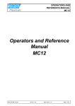
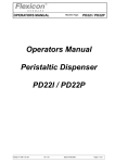
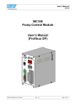
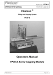
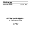
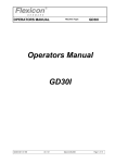
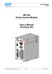
OPERATORS MANUAL
Machine Type:
MC12
Operators Manual
MC12
MC12 OM 1.02 EN
Ver 1.02
Date 24-08-2006
Page 1 of 23
OPERATORS MANUAL
Machine Type:
MC12
1
DECLARATION OF CONFORMITY................................................................................ 3
2
GENERAL INFORMATION............................................................................................. 4
2.1
2.2
2.3
3
3.1
3.2
4
4.1
4.2
4.3
4.4
4.5
4.6
4.7
5
5.1
5.2
5.3
6
6.1
6.2
6.3
6.4
6.5
6.6
7
7.1
7.2
7.3
UNPACKING AND INSPECTION .......................................................................................... 4
USE .............................................................................................................................. 4
CONNECTIONS ............................................................................................................... 4
CONTROL ...................................................................................................................... 6
DISPLAY ........................................................................................................................ 6
KEYPAD ........................................................................................................................ 7
PROGRAMMING ............................................................................................................ 8
STARTING THE MC12..................................................................................................... 8
PASSWORD PROTECTION ............................................................................................... 8
PARAMETERS ................................................................................................................ 9
PROGRAMS ................................................................................................................... 9
GENERAL INFORMATION ON THE PROGRAMMING OF MC12................................................ 9
LIST OF FUNCTIONS ...................................................................................................... 10
DESCRIPTION OF FUNCTIONS ........................................................................................ 11
.DAILY USE .................................................................................................................. 17
USED AS A DISPENSER ................................................................................................. 17
TERMINATE DISPENSING ............................................................................................... 18
CONTINUOUS RUN........................................................................................................ 18
CALIBRATION.............................................................................................................. 19
CALIBRATION WITH MEASURING CYLINDER ..................................................................... 19
CALIBRATION WITH BALANCES ...................................................................................... 20
CALIBRATION OF GRAMS WITH BALANCE ........................................................................ 20
RECALIBRATION ........................................................................................................... 21
CALIBRATION IN PARALLEL MODE .................................................................................. 22
CALIBRATION IN SERIAL MODE ....................................................................................... 22
CLEANING AND MAINTENANCE ................................................................................ 23
DAILY CLEANING .......................................................................................................... 23
STERILISATION ............................................................................................................ 23
MAINTENANCE ............................................................................................................. 23
MC12 OM 1.02 EN
Ver 1.02
Date 24-08-2006
Page 2 of 23
OPERATORS MANUAL
Machine Type:
MC12
1 DECLARATION OF CONFORMITY
We
Flexicon A/S
Frejasvej 2-6
DK-4100 Ringsted
declare on our sole responsibility that the product:
MC12 Master Controller
Denmark
Model:
MC12
Serial No:
yymm xxxx
Supply:
230V / 50/60 Hz / 50W
Year:
2006
Made in Denmark
to which this declaration relates is in conformity with the following standard(s):
DS/EN ISO 12100
DS/EN 60204
Safety of machinery - Basic concepts, general
principles of design
Safety of machinery – Electrical equipment of
machines
according to the provisions in the Directives:
98/37/EC
73/23/EEC
2004/108/EC
On the approximation of the laws of the Member
States relating to machinery.
On the harmonization of the laws of Member States
relating to electrical equipment designed for use
within certain voltage limits
On the approximation of the laws of the Member
States relating to electromagnetic compatibility
Ringsted, August 2006
MC12 OM 1.02 EN
Ver 1.02
Mads Ulric Jensen
Signature.
Date 24-08-2006
Page 3 of 23
OPERATORS MANUAL
Machine Type:
MC12
2 GENERAL INFORMATION
2.1
Unpacking and inspection
After checking that all ordered items have been received, please check that they were not
damaged during transport. In case of any defects or shortcomings, please contact
Flexicon A/S or your supplier immediately.
In case of future need of spare parts for this machine, please, when ordering, indicate the
serial number stamped on the label on the bottom of the machine.
ALWAYS REMEMBER that this machine must be earthed via its main cable.
2.2
Use
MC12 is the main computer of the Flexicon Multi Filling System (FMFS). MC12 can not
perform filling by itself, but is developed for controlling one of Flexicons pumps for
example PD12 or PD22 series.
2.3
Connections
It is important that MC12 is placed on a stable bedplate and that liquids are not splashed
onto it.
120 / 240 V
Fig. 2.1
The main cable supplied is connected to the main socket (1). The plug is connected to an
earthed switch.
The communication cable (type 3) comes fitted with two 4-pin DIN plugs. One is
connected to the “net” socket (2) of MC12, and the other plug is connected to the “net 1”
socket of the required pump.
MC12 OM 1.02 EN
Ver 1.02
Date 24-08-2006
Page 4 of 23
OPERATORS MANUAL
Machine Type:
MC12
The terminator supplied (4-pin blind Din plugs) is connected to the “net 2” socket of the
filling station.
MC12 is now ready to be switched on and to control the connected filling station.
Should it be required to connect more than one filling station to the same MC12 or to
connect other equipment to it, the operators manual supplied for the filling station should
be consulted.
MC12 OM 1.02 EN
Ver 1.02
Date 24-08-2006
Page 5 of 23
OPERATORS MANUAL
Machine Type:
MC12
3 CONTROL
3.1
Display
The display of MC12 consists of 4 lines each of 40 characters. The display is lit from the
back.
The blinking cursor of the display shows where a character will occur, if a key is activated.
ENTER FUNCTION No. :
F 1: 100.00 ml.
F 2: 8.0 TUBE
F 3: 200 rpm
F 4: 10 ACC
F 5: 0 REV.
F 6: 1 fills
P1
Fig. 3.1
The top line is the typing line and also the line, where MC12 prompts the operator.
The second last character on the top line (P) indicates the operation principle of MC12:
Parallel (P).
The ultimate character of the top line (1) indicates the pump connected.
The three lines below are status lines which always shows the current operating
parameters. These status lines can be scrolled by pressing the Up or Down Arrow of the
keyboard.
When operating MC12, it is VERY important to watch the top line constantly, as any
current question or instruction will be written here.
MC12 OM 1.02 EN
Ver 1.02
Date 24-08-2006
Page 6 of 23
OPERATORS MANUAL
Machine Type:
MC12
3.2 Keypad
The MC12 comes with a membrane-type keypad. The keypad is sealed and flat and can
be cleaned with alcohol and other detergents.
7
8
9
C
4
5
6
.
calib.
1
2
3
0
ENT
7
8
9
C
4
5
6
.
1
2
3
0
C
Y
N
disp.
pump
GO
STOP
Numerical keys 0 to 9 as well as decimal point.
“C” : Cancel
Delete Character to the left of the cursor
Scroll the status line one line up
Scroll the status line one line down
ENT
Y
YES key for YES/NO qustions on display
N
NO key for YES/NO qustions on display
disp.
Activates filling
pump
Activates continous pumping
calib.
Activates calibration
GO
Start Button
STOP
Stop Button
Enter / return to enter values typed on the keyboard.
Fig. 3.2
MC12 OM 1.02 EN
Ver 1.02
Date 24-08-2006
Page 7 of 23
OPERATORS MANUAL
Machine Type:
MC12
4 PROGRAMMING
4.1
Starting the MC12
In the following, the sign <> will mean that the indicated key must be activated. For
instance, <ENT> means that ENTER must be pressed.
When the MC12 is connected, the main switch on the left side of the control box can be
turned on.
The display will show the following:
STANDBY
Fig. 4.1
Press the <GO> key, and the display will show the following:
* MC12 V1.XX (C) Flexicon 90-XX *
PRESS GO TO CONTINUE.
DRIVE No.: 1
Fig. 4.2
Verify that all connected drives are displayed with their respective numbers.
Then press <GO> once more, and the display will show the following:
ENTER FUNCTION NO. :
F 1: 100.00 ml.
F 2: 8.0 TUBE
F 3: 200 rpm
F 4: 10 ACC
F 5: 0 REV.
F 6: 1 FILLS
I1
Fig. 4.3
The values shown in the status lines will be the above or the latest values used.
4.2
Password Protection
MC12 is password protected. To be able to perform the following programming procedures
it is necessary to log on as a supervisor (see function 59).
Always remember to change the password level back to user level after programming.
MC12 OM 1.02 EN
Ver 1.02
Date 24-08-2006
Page 8 of 23
OPERATORS MANUAL
Machine Type:
MC12
Remember that merely switching MC12 off/on will NOT change any selected password
level! The MC12 is now ready to be programmed.
If the MC12 is a FMB210 or FP50 version the password level can also be changed by
entering the supervisor password on the control panel touch screen.
4.3
Parameters
In the following a parameter will be a single value like for example volume, velocity,
number of fillings etc.
4.4
Programs
In the following a program will be a complete set of parameters which together form a
program according to which MC12 and the connected pump will operate.
4.5
General information on the programming of MC12
MC12 is equipped with a battery in the memory and will therefore always remember the
programmed parameters, even if the main switch is turned off.
The programming is made via functions, i.e. every operating parameter has its own
function number.
The programming is made by entering the function number followed by "ENT".
This will make the required function appear in the prompt line of the display and show the
current value or information of the function.
This value will automatically be overwritten when entering the new value. After being
entered, the new value will be displayed in the prompt line. The new value is entered into
the computer by pressing "ENT".
The new value will be displayed in the status lines at once.
Example:
If a volume of 8.5 ml is required, the following should be entered:
<1>+<ENT>+<8>+<.>+<5>+<ENT>
MC12 knows automatically which filler is connected. Consequently, values which are not
valid for this pump will not be accepted. If a faulty value is entered, it will not be entered,
and a "beep" sound will be heard.
MC12 OM 1.02 EN
Ver 1.02
Date 24-08-2006
Page 9 of 23
OPERATORS MANUAL
4.6
Machine Type:
MC12
List of functions
1. Volume
31. Save program
2. Tube diameter
32. Load program
3. Velocity
33. Delete program
4. Acceleration/deceleration
34. Print programs
5. Reversing (back suction)
35. Free memory capacity
6. Batch size (Disabled in FMB
version)
40. Mode
7. Delay (Disabled in FMB version)
41. Select filler
8. Completed fills
42. Set date
9. Specific gravity
43. Set time
10. Output rate
44. Display time and date
11. Accumulated volume
45. Display filler version
12. Maximum flow rate
46. Select language
16. Pumping direction (GD30I)
47. Printer set-up
17. Timer 1 (Disabled in FMB version)
49. Balance set-up
18. Timer 2
51. Filling needle set-up
19. Timer 3
53. Drive deactivation !!
20. Operator number
58. Set passwords
21. Batch number
59. Change access level
22. Start Log
60. Ext. Input mode (Disabled in FMB version)
23. Stop Log
70. Output format
24. Print Log
71. Flow rate format
25. Delete Log
72. Volume format
26. Log status
73. Display Mc12 version
29. Print parameters
80. Reset memory
86. Complete memory reset
!! Before activating function 53, ALWAYS first press STOP on the FMB touch Screen. If not
the FMB has to be switched OFF and ON before it can be restarted.
MC12 OM 1.02 EN
Ver 1.02
Date 24-08-2006
Page 10 of 23
OPERATORS MANUAL
4.7
Machine Type:
MC12
Description of functions
The individual functions will be described in the following:
1. Volume
Value: Choice of ml and grams as unit.
The required volume from 0.01 to 9999.9 ml, or grams.
To change the volume unit please refer to function 72
2. Tube diameter
Value: The inside diameter of the tube in mm.
Enter the tube diameter used. The MC12 will only accept original Flexicon tube diameters.
The diameters are specified in the manual for the drive and can be read on the tube
gauge supplied with the drive.
3. Velocity
Value: Revolutions per minute.
Enter the required volocity.
The different drives have different ranges, and the range is stated in the drive manual.
4. Acceleration/deceleration
Value: An integral number.
The filling can start and stop more or less abruptly.
This function offers a choice of values between 1 and 200 dependent on the tube size and
drive serie.
1 = slowest acceleration.
i
100/150/200 = fastest acceleration .
5. Reversing (back suction)
Value: An integral number.
When the filling stops, the filler can be asked to produce a small back suction to prevent
dripping.
The back suction can be set to values between 0 and 10.
0 = no back suction.
10 = maximum back suction.
6. Batch size (Disabled in FMB version)
Value: Number.
Enter the number of fillings you want the filler to perform when started by <GO>, foot
switch or via electrical signal.
There is a choice between 1 and 65,000.
When the filler is operating in an automatic system, where the system itself starts the filler
each time a bottle is in position,
THE VALUE IN THIS FUNCTION MUST - ON AN FMB - ALWAYS BE 1.
MC12 OM 1.02 EN
Ver 1.02
Date 24-08-2006
Page 11 of 23
OPERATORS MANUAL
Machine Type:
MC12
7. Delay (Disabled in FMB version)
Value: Seconds.
If more than one fill is selected in Function 6, enter the required delay between the fills.
The value of the delay can range between 0.0 and 25.5 seconds, with intervals of 0.1
second.
8. Completed fillings
Value: Number.
Nothing can be entered in this function, since it only displays the number of fillings
completed since the latest reset of the function.
To reset this function, press the <C> key.
9. Specific gravity
If the product has another spec. gravity then the usual 1.0 (Water), then it is entered here.
The default value is 1.0000 g/ml. Changing specific gravity should be followed by a
calibration .
10. Output rate
Value: Number of fillings per time unit.
Nothing can be entered in this function, as it only displays the current output rate.
To change the time unit, please refer to function 70.
11. Accumulated volume
Value: Litre
Nothing can be entered in this function, since it only displays the total volume used since
the latest reset of the function.
To reset this function, press the <C> key.
12. Maximum flow
Value: Volume per time unit.
Nothing can be entered in this function, since it only displays the current maximum flow.
The read-out is based on the flow created when the rotor runs at the required velocity.
To change the units of measurement, please refer to function 71.
16. Pumping direction
Value: Clockwise or counter-clockwise.
This function works only in connection with the pump GD30I.
17. Timer 1 (Disabled in FMB version)
Value: Seconds.
A time interval can be set between a starting signal and the time the drive actually starts.
The interval is from 0.0 to 25.0 seconds.
MC12 OM 1.02 EN
Ver 1.02
Date 24-08-2006
Page 12 of 23
OPERATORS MANUAL
Machine Type:
MC12
18. Timer 2
Value: Seconds.
A time interval can be set where the status signal says that the filler is operating BEFORE
it actually begins to operate.
The interval is from 0.0 to 25.0 seconds.
19. Timer 3
Value: Seconds.
A time interval can be set where the status signal says that the filler is operating AFTER it
actually stopped.
The interval is from 0.0 to 25.5 seconds.
20. Operator number
An operator number that can be from 1 to 12 digits long can be entered.
21. Batch number
A batch number that can be from 1 to 12 digits long can be entered.
22. Start Log
By this function automatic logging of production data (Log) can be started.
23. Stop Log
By this function the automatic logging of production data (Log) is stopped.
24. Print Log
If a printer is connected, this function will start the printing of the log. It is possible to
choose between printing the complete log immediately without deleting it and continuous
printing with contemporary deletion of log-data.
25. Delete Log
Deletes the Log memory.
26. Log Status
This function displays the number of used and free bytes in the Log memory.
29. Print parameters
This function prints the current parameters via connected printer.
31. Save program
Saves a complete set of parameters as a program.
It is possible to save 87 set of parameters, i.e. one pump has 87 programs available, and
in case of two pumps, each have 43 programs available.
MC12 OM 1.02 EN
Ver 1.02
Date 24-08-2006
Page 13 of 23
OPERATORS MANUAL
Machine Type:
MC12
32. Load program
Loads a program already saved and overwrites the current parameters with the values of
the program.
33. Delete program
This function deletes the required program.
34. Print programs
This function prints the individual parameters in all the programs stored in the memory.
35. Free memory capacity
Displays the number of used and free programs in the memory.
40. Operating principle (mode)
Value: An integral number.
If more than one pump is connected, MC12 can operate according to three different
principles:
1 - individual
2 - parallel
3 - serial
Please consult the reference manual for further information.
41. Select filler (drive)
If several pumps are connected, this function is used for selecting the number of the filler
to be shown on the display and to be controlled via the keyboard.
42. Set date
Please consult the reference manual.
43. Set time
Please consult the reference manual.
44. Display time and date
Will display time and date on display.
45. Display pump version
This function displays the type and version of the pump.
46. Select language
Value: An integral number.
This function offers a choice of four languages:
1 - Danish
2 - English
3 - German
4 - French
The language returns to the default after re-start or function 80 has been applied.
MC12 OM 1.02 EN
Ver 1.02
Date 24-08-2006
Page 14 of 23
OPERATORS MANUAL
Machine Type:
MC12
47. Printer set-up
Please consult the reference manual.
49. Balance set-up
This function provides the possibility to connect MC12 to an electronic balance. The
balance which can be used are Mettler® and Sartorius®. Furthermore it is possible to
choose between dynamic calibration and direct filling on balance.
Pleas consult the reference manual for further information.
51. Filling needle set-up
If the machine is required to operate with a pneumatic bottom-up or an electrical filling
equipment, this is indicated by entering the number for the actual system as listed below
in functions and then follow the instructions in the prompt line.
MC12 will then control the movement of the filling nozzle in step with the pump in
question.
In case of parallel or serial operating principle, the pump to be followed must ALWAYS be
0.
0 - No moving of filling nozzles (Standard setting on FMB)
0- Pneumatic Dumping Nozzle
1 - Pneumatic bottom-up filling system
2 - Electrical Dumping Nozzle
3 - Electrical bottom-up
For further information please refer to the reference manual.
53. Activating/Deactivating drives
With this function it is possible to activate or deactivate the connected pumps.
N.B. Before activating function 53, ALWAYS first press STOP on the FMB touch Screen
panel. If not the FMB has to be switched OFF and ON before it can be restarted.
58. Set Passwords
This functions sets the passwords for the 3 different levels.
Level 1 – Unlimited access.
Level 2 – Basic functions
Level 3 – Restricted to <calib>, 41 (display tube size in serial mode) and 59. (Change
access level) only.
59. Change access level
Key in the password for the required level, as set in function 58.
Dispays the current password level.
MC12 OM 1.02 EN
Ver 1.02
Date 24-08-2006
Page 15 of 23
OPERATORS MANUAL
Machine Type:
MC12
60. Operating mode for ext. connections (Disabled in FMB version)
Mode 1 or 2.
This function is activated when using foot switch in order to start/stop filling.
1- Foot-switch used only as start (Standard setting on FMB)
2- First push starts Second push stops Third push starts etc.
70. Capacity format
Changes the unit for F10. fills/min or fills/hour
71. Flow rate format
For further information please refer to the reference manual.
72. Volume format
Changes the unit for F1 and F11. ml or g
73. Display MC12 version
This function displays the type, version and date of the MC12 software.
80. Reset memory
This function resets the memory with the exception of the part used for saving programs.
MC12 goes into stand-by. When switched on again the built-in parameters are active.
IF MC12 DOES NOT WORK OR DOES NOT OPERATE AS EXPECTED,
ACTIVATE FUNCTION 80
86. Complete memory reset
This function works in the same manner as Function 80 but includes also the part of the
memory containing programs saved via Function 31. This function should only be used for
extreme cases.
Function 86 is not shown in the status lines of the display. A calibration is necessary after
using function 86.
MC12 OM 1.02 EN
Ver 1.02
Date 24-08-2006
Page 16 of 23
OPERATORS MANUAL
Machine Type:
MC12
5 .DAILY USE
5.1
Used as a dispenser
Switch on MC12 and press <GO> twice.
Program example with PD12 as a filler:
Volume: 8.5 ml.
Tube: 3.2.
Velocity: 400 rpm.
Acceleration: 35.
Small back suction.
100 fillings to be completed.
An interval of 1.1 seconds between the fillings.
specific gravity for instance, water
The above job shall be programmed as follows:
Volume:
Tube:
Velocity:
Acceleration:
Back suction:
Number of fillings:
Intervals:
Specific gravity
<1>+<ENT>+<8>+<.>+<5>+<ENT>
<2>+<ENT>+<3>+<.>+<2>+<ENT>
<3>+<ENT>+<4>+<0>+<0>+<ENT>
<4>+<ENT>+<3>+<5>+<ENT>
<5>+<ENT>+<1>+<ENT>
<6>+<ENT>+<1>+<0>+<0>+<ENT>
<7>+<ENT>+<1>+<.>+<1>+<ENT>
<9>+<ENT>+<1>+<.>+<0>+<ENT>
You have now programmed MC12 for the job, but want to reset the built-in counters. In
function 8 the counter indicates "number of completed fillings" and in function 11 "total
volume dispensed".
Number of fillings: <8>+<ENT>+<C>+<ENT>
Total volume:
<11>+<ENT>+<C>+<ENT>
Then just inform MC12 that you want fillings by pressing <disp.>.
Every time <GO> or the foot switch is pressed, or every time an electric signal is given, the
filler carry out 100 fillings of 8.5 ml at an interval of 1.1 seconds between each filling.
Press <GO>, verify that the filler starts and let it run.
Press Arrow Down twice, and on the status lines that F8: and F11: are counting each
filling.
F10: gives a current indication of the number of fillings completed per minute.
MC12 OM 1.02 EN
Ver 1.02
Date 24-08-2006
Page 17 of 23
OPERATORS MANUAL
5.2
Machine Type:
MC12
Terminate dispensing
When the filler has completed the number of fillings asked for in F6: it stops automatically.
If <GO> is pressed again, the filler completes the programmed number of fillings once
more.
If you want to stop the fillings, before the programmed number has been completed, press
<STOP>, and the filler stops after completing the filling in progress.
The filling series can be completed by pressing <GO>.
If you want to stop IMMEDIATELY, also in the middle of a filling, press <STOP> twice, and
the filler stops immediately.
The filling series can be completed by pressing <disp.>+<GO>, and the interrupted filling
are counted in.
5.3
Continuous run.
MC12 can also control a filler as a pump so the pump runs continuously.
The pumping is started by pressing <pump>+<GO>.
The filler starts with the entered acceleration and runs up to the required number of
revolutions per minute.
The filler runs at this velocity until stopped by pressing <STOP>.
In function 12 the current uncalibrated flow can be read.
If an exact flow read-out is required, the system must be calibrated. This calibration shall
be made as indicated in paragraph 5: CALIBRATION.
It is recommended to use a rather long filling for this calibration of the flow value.
MC12 OM 1.02 EN
Ver 1.02
Date 24-08-2006
Page 18 of 23
OPERATORS MANUAL
Machine Type:
MC12
6 CALIBRATION
As the surroundings may vary from time to time and as tubes and products have small
tolerance deviations, it is necessary to calibrate the filler when it is started.
If the quantity has been entered as volume in ml, a measuring cylinder or a balance may
be used as control and measuring unit. The balance will always be most accurate,
especially when the quantities are small.
6.1
Calibration with measuring cylinder
(The parameters already entered may be used for a trial).
Prepare the measuring cylinder and make sure that the tubes are completely filled, up to
and including the filling nozzle.
(It is recommended to let the filler complete a few fillings before the calibration is made.
After these fillings, set F9, reset F8: and F11:).
Keep the measuring cylinder below the filling nozzle and press <calib.>+<GO>. The filler
will complete ONE trial filling, and the display will now show the following:
CALIBRATION WEIGHT:
F 1: 8.50 ml
F 3: 400 rpm
F 5: 1 REV.
0.0000
F 2: 3.2 TUBE
F 4: 35 ACC
F 6: 100 fills
I1
Fig. 6.1
It will be observed that the MC12 in the prompt line asks for the weight.
THE WEIGHT MUST BE ENTERED, e.g. 8.05: <8>+<.>+<0>+<5>+<ENT>.
The filling may begin by pressing <disp.>+<GO>.
MC12 OM 1.02 EN
Ver 1.02
Date 24-08-2006
Page 19 of 23
OPERATORS MANUAL
6.2
Machine Type:
MC12
Calibration with balances
(The parameters already entered may be used for a trial).
Reset the balance with the container (bottle) to be used for the trial filling and make sure
that the tubes are completely filled, up to and including the filling nozzle.
(It is recommended to let the filler complete a few fillings before the calibration is made.
After these fillings, set F9, reset F8: and F11:).
Keep the container below the filling nozzle and press <calib.>+<GO>. The filler will
complete ONE trial filling, and the display will now show the following:
CALIBRATION WEIGHT:
F 1: 8.50 ml
F 3: 400 rpm
F 5: 1 REV.
0.0000
F 2: 3.2 TUBE
F 4: 35 ACC
F 6: 100 fills
I1
Fig. 6.2
It will be observed that the MC12 in the prompt line asks for the weight, and the value
shown on the balance must be entered, e.g. 8.25: <8>+<.>+<2>+<5>+<ENT>.
The filling may begin by pressing <disp.>+<GO>.
6.3
Calibration of grams with balance
A MC12 programmed to fill a quantity measured in grams, should be calibrated by means
of a balance.
(The parameters already entered may be used for a trial, where the 8.5 ml equals 8.5
grams). i.e. Specific gravity is 1.0000 g/ml
Reset the balance with the container (bottle) to be used for the trial filling and make sure
that the tubes are completely filled up to and including the filling nozzle.
(It is recommended to let the filler run a few fillings before the calibration is made. After
these fillings, set F9, reset F8: and F11:).
Keep the container under the filling nozzle and press <calib.>+<GO>. The filler makes
ONE trial filling, and the display now shows the following:
CALIBRATION WEIGHT:
F 1: 8.50 ml
F 3: 400 rpm
F 5: 1 REV.
MC12 OM 1.02 EN
Ver 1.02
0.0000
F 2: 3.2 TUBE
F 4: 35 ACC
F 6: 100 fills
Date 24-08-2006
I1
Page 20 of 23
OPERATORS MANUAL
Machine Type:
MC12
Fig. 6.3
It can be observed that the MC12 in the prompt line asks for the weight, and the value
shown on the balance must be entered, e.g. 8.25: <8>+<.>+<2>+<5>+<ENT>, If grams is
selected as volume format in function 72, the calibration will now be completed.
The filling may begin by pressing <disp.>+<GO>.
6.4
Recalibration
During the production it may be necessary to recalibrate the volume dispensed by the
filler, as for example the liquid level of the suction vessel will sink. This recalibration can be
made without stopping the fillings.
IT IS IMPORTANT TO USE THE SAME MEASURING METHOD FOR THE
RECALIBRATION AS USED FOR THE INITIAL CALIBRATION.
Draw off a filling sample and measure it.
Press <calib.>+<ENT>, and the display will show the following:
RECALIBRATION WEIGHT:
F 1: 8.50 ml
F 3: 400 rpm
F 5: 1 REV.
0.0000
F 2: 3.2 TUBE
F 4: 35 ACC
F 6: 100 fills
I1
Fig. 6.4
Enter the measured value, e.g. 8.47: <8>+<.>+<4>+<7>+<ENT>, and MC12 will now
automatically correct the filler from 8.47 to 8.5 as asked.
MC12 uses the specific gravity entered in F9.
MC12 OM 1.02 EN
Ver 1.02
Date 24-08-2006
Page 21 of 23
OPERATORS MANUAL
6.5
Machine Type:
MC12
Calibration in parallel mode
When MC12 is working with several pumps in parallel mode the system is controlled from
Drive 0.
When calibration or recalibration is needed, at first the MC12 will ask for the actual drive
and when this information has been keyed in, the procedure will be the same as described
above.
6.6 Calibration in serial mode
When MC12 is working with several pumps in serial mode the system is controlled from
Drive 0.
When calibration or recalibration is needed, the MC12 will consider all drives as being one
single filler and the procedure will be the same as described above.
MC12 OM 1.02 EN
Ver 1.02
Date 24-08-2006
Page 22 of 23
OPERATORS MANUAL
Machine Type:
MC12
7 CLEANING AND MAINTENANCE
7.1 Daily cleaning
As MC12 is not in contact with the dispensed product, daily cleaning will not be necessary
except for the normal routine cleaning of production equipment.
When cleaning, please note that the cabinet of MC12 is provided with open slots for the
cooling of the built-in parts. Therefore, liquids must NOT be splashed onto MC12. It may
only be cleaned with a damp piece of paper or cloth.
The cabinet is made of anodised aluminium and plastics, and normal detergents as spirit
and isopropanol may be used.
7.2 Sterilisation
If MC12 shall be placed in aseptic environments, the sterilisation may be made as
described in paragraph 6.1, or you may sterilise MC12 by gasses observing the following
precautions.
If you use gasses that might injure and corrode contacts and other metals, air slots and
sockets MUST be covered with tape.
7.3
Maintenance
As there are no movable parts in MC12, no other maintenance is required than normal
cleaning of the equipment.
If service should be needed, please consult the reference manual.
Should any further service be needed, please contact Flexicon A/S or your supplier.
COPYRIGHT
*********
Copyright (c) 2006 Flexicon A/S. All rights to this manual belong to Flexicon A/S. Neither
the complete manual nor parts of it may be translated, copied, printed or published in any
form or by any means without permission in writing from Flexicon A/S
Flexicon A/S is convinced that the information of this manual is correct, but Flexicon A/S
can not be held responsible for it.
Flexicon A/S reserves the right to update and amend this manual without previous notice.
Flexicon A/S is under no obligation to update manuals already published.
MC12 OM 1.02 EN
Ver 1.02
Date 24-08-2006
Page 23 of 23