1
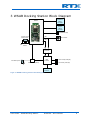
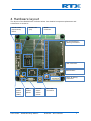
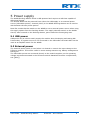
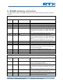
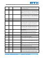
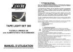
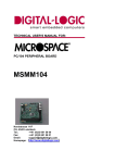
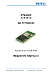
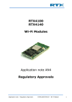
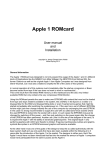
RTX4100
Wi-Fi Module
User Guide
WSAB Docking Station [UG7]
User Guide – WSAB Docking Station
RTX4100 – Wi-Fi Module
1
CONTENT
1
Introduction ............................................................................................................................................ 3
1.1
General Description .................................................................................................................................. 3
1.2
Document History ..................................................................................................................................... 3
1.3
SW/HW Version ........................................................................................................................................ 3
1.4
Document References .............................................................................................................................. 3
2
Features .................................................................................................................................................. 5
3
WSAB Docking Station Block Diagram ..................................................................................................... 6
4
Hardware layout ..................................................................................................................................... 7
5
Power supply .......................................................................................................................................... 8
5.1
USB power ................................................................................................................................................ 8
5.2
External power .......................................................................................................................................... 8
6
WSAB docking connector ........................................................................................................................ 9
7
Expansion-/debug-connector ................................................................................................................ 11
8
Current profile measurements .............................................................................................................. 13
9
Board documentation ........................................................................................................................... 14
10
Abbreviations ....................................................................................................................................... 17
11
Liability Disclaimer ................................................................................................................................ 18
User Guide – WSAB Docking Station
RTX4100 – Wi-Fi Module
2
1 Introduction
1.1 General Description
The RTX4100 Wi-Fi Module is a small form-factor, single stream, 802.11b/g/n Wi-Fi module with on-board low power application processor. It is targeted at applications that
send infrequent data packets over the network. Typically, these 802.11 applications will
place a higher priority on system cost, power consumption, ease of use, and fast wakeup times as compared to high throughput.
This document serves as a manual for the WSAB Docking Station. With the Wi-Fi Sensor
Application Board (WSAB) inserted in the Docking Station it is possible to develop and
test applications running on the RTX4100 module. The WSAB Docking Station provides
the WSAB and RTX4100 module with power, either USB power or an external lab supply
is supported. The USB interface on the WSAB Docking Station provides two virtual COM
ports on the PC which can be used for basic CoLA application development and
debugging. Advanced application development and debugging is supported by connecting
an RTX2040 Unity-II debugger (must be bought separately). Further the WSAB Docking
Station provides a pin header for hardware prototyping and application development.
For further information on the WSAB please refer to ([UG6]).
1.2 Document History
V1.2, Updated references
TM
2013-02-19
TM
2012-10-29
V1.1,
-Docking connector J9 pin
23 and 26 description
corrected.
-Added description of WSAB
pin functions in table
documenting the docking
connector J9
-Updated board
documentation
V1.0, Official release
TM
2012-07-08
Disclaimer: This document can be subject to change without prior notice.
1.3 SW/HW Version
This document is applicable for the following versions.
WSAB_DOCK version V2RA (PCB partnumber 81902912)
1.4 Document References
[DS1]. RTX4100_Datasheet_DS1.pdf.
[DS2]. RTX4140_Datasheet_DS2.pdf.
[UG3]. RTX4100_User_Guide_Application_Development_UG3.pdf.
User Guide – WSAB Docking Station
RTX4100 – Wi-Fi Module
3
[UG4]. RTX4100_User_Guide_Application_Debugging_UG4.pdf.
[UG5]. RTX4100_User_Guide_Platform_Update_UG5.pdf.
[UG6]. RTX4100_User_Guide_WSAB_UG6.pdf.
User Guide – WSAB Docking Station
RTX4100 – Wi-Fi Module
4
2 Features
The WSAB Docking Station includes the following features.
WSAB Docking connector: The Wi-Fi Sensor Application Board (WSAB) docking
connector accepts the WSAB with the RTX4100 Wi-Fi Module.
Mini USB connector: The USB connector can provide the WSAB Docking Station
and the docked WSAB with power. Meaning that no external power supply is
needed for SW development. Further the USB interface provides two virtual COM
ports on the PC. The COM ports can be used for basic COLA application
development and debugging, see ([UG3]) and ([UG4]).
Virtual COM port activity LEDs: Two dual color LEDs indicate activity on the
virtual COM ports provided through the USB interface
WSAB LED duplicate: One dual color LED on the WSAB Dock connected in
parallel with the LED on the WSAB makes it easy to se the LED status with the
WSAB docked.
40 pin expansion-/debug-connector: Expansion connector, with all RTX4100
IO’s available, for adding customized application add-on boards. Can be used for
adding new sensor devices, power supplies etc.
Boot button: The Boot button is used for platform formware updates, see
reference ([UG5]). For CoLA application updates the Boot button is not required.
Power supply: The WSAB can be powered from the USB connector or from an
external power supply. The power source can be selected using a switch on the
WSAB Docking Station.
Current sensing resistor: A resistor in the ground path of the external power
supply enables characterization of the current profile of the application simply by
using an oscilloscope.
RTX Unity-II debug connector: For advanced application development and
debugging an RTX2040 Unity-II debugger can be connected (must be bought
separately)
Small form factor: 86x86mm
User Guide – WSAB Docking Station
RTX4100 – Wi-Fi Module
5
3 WSAB Docking Station Block Diagram
40 pin
expansion-/
debugconnector
WSAB
RTX2040
Unity-II
debug
connector
WSAB LED (D3)
Current sense
solder points
US1
Boot button
LEU1
Current sense
resistor
Level
conversion
USB
controller
VIN solder points
Power switch (SW3)
LEU1 activity LED (D2)
US1 activity LED (D1)
Mini USB
connector
Figur 1 WSAB Docking Station blockdiagram
User Guide – WSAB Docking Station
RTX4100 – Wi-Fi Module
6
4 Hardware layout
The layout of the WSAB Dock is shown below. See detailed component placement and
schematics in section 9.
Virtual COM
port activity
LED’s
WSAB LED
(D3)
WSAB
connector
40 pinexpansion/debug-connector
USB controller
Boot button
Unity-II debug
connector
WSAB
power
switch
(SW3)
VIN
solderpoints
Current
sensesolderpoints
User Guide – WSAB Docking Station
Mini USB
connector
RTX4100 – Wi-Fi Module
7
5 Power supply
The WSAB Docking Station board is USB powered and requires a USB host capable of
delivering 500mA.
The docked WSAB can be powered from either the USB supply or an external power
source (VIN solder points). A switch (SW3) in the WSAB Docking Station can be used to
with between the two power options.
Note! Be certain that the switch on the WSAB is set to external power source when using
the supply options from the Docking Station. The supply selection switch on the WSAB
should, when monted on the Docking Station, point toward the Prototyping area.
5.1 USB power
USB power can be used to easily supply the module when developing and testing SW
functionality. If a power source is not connected to the VIN solder terminals SW3 can be
used as an ON/OFF switch for the WSAB.
5.2 External power
The external power option is used when it is desired to control the input voltage to the
RTX4100 module. This will be usefull in some testing scenarios eg. battery management
testing etc.
The VIN solder points are connected directly to the module supplies, so the operating
voltage requirements stated in the RTX4100 module datasheet must be complied with,
see ([DS1]).
User Guide – WSAB Docking Station
RTX4100 – Wi-Fi Module
8
6 WSAB docking connector
The table below shows the WSAB connections in the WSAB docking connectors and their
function.
Docking connector J1
J1 Pin
no.
Type
Module pin name
WSAB Docking Station function
1
2
3
4
5
I/O
O
I/O
I/O
I/O
PA0
RESETn
PA1
PB12
PA3/PC1
6
7
I/O
I/O
PB8
PA4/PC0
8
9
10
11
GND
I/O
I/O
GND
12
13
14
I/O
I/O
I/O
Connected to Expansion connector (J9)
Connected to Expansion connector (J9)
Connected to Expansion connector (J9)
Connected to Expansion connector (J9)
US1_RX
UART_RX signal used for eg. COLA application
download and debugging via USB virtual COM
port.
Also connected to Expansion connector (J9)
Connected to Expansion connector (J9)
US1_TX
UART_TX signal used for eg. COLA application
download and debugging via USB virtual COM
port.
Also connected to Expansion connector (J9)
GND_WSAB
Connected to Expansion connector (J9)
Connected to Expansion connector (J9)
AGND
Analog ground may be used as reference for
RTX4100 analog I/O’s
Connected to Expansion connector (J9)
Connected to Expansion connector (J9)
Connected to Expansion connector (J9)
Connected to Expansion connector (J9)
GND
PB7
PB13
GND
PB14
PC4/PD4
PC5/PB11
Docking connector J3
J3 Pin
no.
Type
Module pin name
WSAB Docking Station function
1
Power
VCC2(*)
2
Power
VIO
3
I/O
PF2
4
5
I/O
I/O
PD5
PF0
+3V5
Step up voltage from WSAB
Connected to Expansion connector (J9)
VDD_EFM
VIO reference voltage for RTX2040 Unity-II
(J4)
Also connected to Expansion connector (J9)
Activates red color in D3 LED
Connected to Expansion connector (J9)
Connected to Expansion connector (J9)
DBG_SWCLK
Clock for RTX2040 Unity-II (J4)
User Guide – WSAB Docking Station
RTX4100 – Wi-Fi Module
9
6
I/O
PF1
7
I/O
PC2
8
9
I/O
I/O
PC3
PC6
10
I/O
PC7
Connected to Expansion connector (J9)
DBG_SWDIO
Data for RTX2040 Unity-II (J4)
Also connected to Expansion connector (J9)
Activates green color in D3 LED
Connected to Expansion connector (J9)
Connected to Expansion connector (J9)
LEU1_TX
Low energy UART_TX signal used for terminal
demo application via USB virtual COM port
Also connected to Expansion connector (J9)
LEU1_RX
Low energy UART_RX signal used for terminal
demo application via USB virtual COM port
Also connected to Expansion connector (J9)
GND_WSAB
VEXT
WSAB power supplied from SW3. Can be set
for either USB or external power
Also connected to Expansion connector (J9)
13
Power
VBAT+ from WSAB
Also connected to Expansion connector (J9)
14
Power
VBAT- from WSAB
Also connected to Expansion connector (J9)
(*) Only valid when WSAB is configured for 2-cell operation. 2-cell operation is the
default configuration.
11
12
GND
Power
GND
User Guide – WSAB Docking Station
RTX4100 – Wi-Fi Module
10
7 Expansion-/debug-connector
The expansion connector, with all RTX4100 module IO’s available, can be used for adding
customized application add-on boards. eg. adding new sensor devices, power supplies
etc..
The below table shows the pinout of the expansion-/debug-connector.
Docking connector J9
J9 Pin
no.
Type
Module pin name
1
2
GND
Power
3
GND
4
5
Power
I/O
PA0
6
I/O
PA1
7
I/O
PB12
8
I/O
PD5
9
I/O
PC2
10
I/O
PC3
11
I/O
PC4/PD4
12
I/O
PC5/PB11
13
I/O
PF2
14
I/O
PB13
15
GND
GND
16
I/O
PB14
17
18
GND
Power
19
GND
VIO
VIO
User Guide – WSAB Docking Station
WSAB Docking Station function
GND
VDD_EFM
RTX4100 module VIO reference voltage
GND_WSAB
Supply current by external connected circuitry
using this ground reference will be included in
the current measurement using the current
sense solder points.
VBAT+ from WSAB
See module pin name (reserved for i2C
communication on the WSAB)(*)
See module pin name (reserved for i2C
communication on the WSAB) (*)
See module pin name (reserved for MEMS on
WSAB) (*)
See module pin name (resered for user key on
WSAB) (*)
Activates red color in D3 LED
See module pin name
See module pin name (resered for user key on
WSAB) (*)
See module pin name (resered for sensor on
WSAB) (*)
See module pin name (reserved for MEMS on
WSAB) (*)
Activates green color in D3 LED
See module pin name
See module pin name (resered for 2-cell stepup converter on WSAB) (*)
AGND
Analog ground may be used as reference for
RTX4100 analog I/O’s
See module pin name (reserved for MEMS on
WSAB) (*)
GND
VDD_EFM
RTX4100 module VIO reference voltage
GND_WSAB
Supply current by external connected circuitry
RTX4100 – Wi-Fi Module
11
20
21
Power
I/O
22
I/O
PA4
23
I/O
PB7
24
25
I/O
I/O
PB8
PC6
26
I/O
PC7
27
I/O
PF0
28
I/O
PF1
29
30
I
31
O
32
I
33
O
34
I
35
36
GND
Power
37
GND
PA3/PC1
RESETn
VCC2(**)
VIO
User Guide – WSAB Docking Station
using this ground reference will be included in
the current measurement using the current
sense solder points.
VBAT+ from WSAB
US1_RX
UART_RX signal used for eg. CoLA application
download and debugging via USB virtual COM
port.
Also connected to Expansion connector (J9)
US1_TX
UART_TX signal used for eg. CoLA application
download and debugging via USB virtual COM
port.
Also connected to Expansion connector (J9)
See module pin name (unused on WSAB)
See module pin name (unused on WSAB)
LEU1_TX
Low energy UART_TX signal used for terminal
demo application via USB virtual COM port
Also connected to Expansion connector (J9)
LEU1_RX
Low energy UART_RX signal used for terminal
demo application via USB virtual COM port
Also connected to Expansion connector (J9)
DBG_SWCLK
Clock for RTX2040 Unity-II (J4) if not using
RXT2040 the pin is free for IO functions
DBG_SWDIO
Data for RTX2040 Unity-II (J4) if not using
RXT2040 the pin is free for IO functions
See module pin name
+3V5
Step up voltage from WSAB
ADBUS2
Control signal from USB controller (for future
use)
ADBUS3
Control signal from USB controller (for future
use)
ADBUS4
Control signal from USB controller (for future
use)
PWREN_EXTn
Power enable (for future use)
GND
VDD_EFM
RTX4100 module VIO reference voltage
GND_WSAB
Supply current by external connected circuitry
using this ground reference will be included in
the current measurement using the current
RTX4100 – Wi-Fi Module
12
sense solder points.
VBAT+ from WSAB
VUSB
USB power from mini USB connector
40
Power
VUSB_SW_PROT
USB power switched on when enumerated for
500mA by the USB host. The output is
protected by a resettable fuse.
(*) To free the pins for IO functions connected via the docking connector J9 please refer
to the WSAB schematics, see ([UG6]).
(**) Only valid when WSAB is configured for 2-cell operation. 2-cell operation is the
default configuration.
38
39
Power
Power
8 Current profile measurements
The current sensing resistor (R7=0,1 Ohm) is placed in the ground path of the WSAB.
This provides the option of characterizing the current profile of the application simply by
using an oscilloscope. Measurements can be done using the solderpoints near R7 using a
1x probe. Connect the probe ground to the round solderpoint and the probe tip to the
square solderpoint. A momentary current of 100mA will translate to -10mV on the
oscilloscope. Therefore the signal should be inverted in the oscilloscope channel setup.
The measurements can be used to profile or watch the active current consumption when
developing and testing applications. Due to the low value of the resistor the
measurements are only valid in active states with Wi-Fi activity. Sleep currents are too
low to measure using the current sensing resistor, and should be done by other means.
If external circuitry is added using the expansion connector of the WSAB Docking Station
it is possible to include the current consumption of added peripherals by using the
GND_WSAB pins in J9 as the ground return path for the external circuits. In this way the
total current consumption of a complete application can be evaluated.
User Guide – WSAB Docking Station
RTX4100 – Wi-Fi Module
13
9 Board documentation
User Guide – WSAB Docking Station
RTX4100 – Wi-Fi Module
14
SW3
R11
D
2
VUSB_SW
Max input level: 5.25V
C20
100n
2
TXD_B
External supply voltage input terminals
3
TXD_A
R20
A1
B1
A2
B2
VCCA
DIR
0R0
VEXT
C17
100n
VUSB
TP11
TP12
7
6
PC7/LEU1_RX
R1
PA3/PC1/US1_RX
0R0
1
J8
TP8
N.M.
R12
J7
C21
100uF/6.3V
TP24
G
10K
R10
IC9
74LVC2T45
1
microSMD050
C14
100n
TP25
S
T100
N.M.
R17
3
FDN304P
Level
conversion
TP10
VUSB_SW_PROT
TP7
VUSB_SW
VUSB
VCCB
5
VDD_EFM
8
R21
4
R7
C18
100n
GND
N.M.
TP16
TP14
0R1 1%
PWREN
GND_WSAB
PWREN_EXT
J2
NM.
1
2
IC8
74LVC2T45
2
RXD_B
3
RXD_A
A1
B1
A2
B2
VCCA
DIR
C15
100n
VUSB VUSB
VCCB
R8
470R
4
L1
C12
100n
C11
100n
C7
100n
7
6
PC6/LEU1_TX
R2
PA4/PC0/US1_TX
0R0
1
5
VDD_EFM
R50
1K0
8
C16
100n
GND
C19
100n
SW4
SKHUQEE010
VUSB
600R
C10
10u
C13
100n
R52
46
3
AVCC
VCC
42
VCC
31
14
VCCIOA VCCIOB
ADBUS0
ADBUS1
ADBUS2
ADBUS3
ADBUS4
ADBUS5
ADBUS6
ADBUS7
3V3OUT
8
USBDM
27R
IC1
FT2232D
R53
6
7
7
USBDP
ACBUS0
ACBUS1
ACBUS2
ACBUS3
SI/WUA
27R
R9
5
VUSB
N.M.
C2
47p
IC6
C1
47p
1K5
RSTOUT
4
43
USB Activity LED's
15
13
12
11
10
RXLED_A
TXLED_A
BDBUS0
BDBUS1
BDBUS2
BDBUS3
BDBUS4
BDBUS5
BDBUS6
BDBUS7
XTOUT
48
EECS
1
BCBUS0
BCBUS1
BCBUS2
BCBUS3
SI/WUB
EESK
2
EEDATA
47
TEST
40
39
38
37
36
35
33
32
TXLED_A
9
GND
18
GND
CG
1K0
41
CR
R15
AR
2K7
SML-521MUW
PWREN
GND
34
25
D2-B
2K2
R19
4
3
1
CS
VCC
CLK
TXLED_B
6
CG
2
4
6
8
10
12
14
16
18
20
22
24
26
28
30
32
34
36
38
40
VBAT+
H6
PA1
PD5
PC3
PC5/PB11
PB13_X
PB14_X
3.3mm NP
PA4/PC0/US1_TX
PB8_X
PC7/LEU1_RX
PF1/DBG_SWDIO
H7
+3V5
ADBUS3
PWREN_EXT
VUSB_SW_PROT
3.3mm NP
R16
AG
GND_WSAB
1K0
SML-521MUW
C6
100n
DI
DO
PA3/PC1/US1_RX
PB7_X
PC6/LEU1_TX
PF0/DBG_SWCLK
RESET
ADBUS2
ADBUS4
VUSB
VBAT-
VUSB
D2-A
VUSB
IC2
93LC46B
5
PA0
PB12
PC2
PC4/PD4
PF2
AGND
R14
AG
SML-521MUW
RXLED_B
TXLED_B
1
3
5
7
9
11
13
15
17
19
21
23
25
27
29
31
33
35
37
39
2K7
D1-B
30
29
28
27
26
VDD_EFM
J9
Connector 40 pole
R13
AR
TP6
PWREN
GND
45
CR
SML-521MUW
TXD_B
RXD_B
RXLED_B
AGND
Prototyping area connector
VUSB
D1-A
RXLED_A
XTIN
44
C5
27p
TXD_A
RXD_A
ADBUS2
ADBUS3
ADBUS4
RESET
X1
6.000MHZ
C4
27p
24
23
22
21
20
19
17
16
TP4
1
2
3
4
5
9
8
6
C3
33n
TP3
USB controller
J31
80010A-05G5T
TP5
C9
10n
TP9
TP13
TP15
TP17
C8
10n
VSS
2
VUSB
TP1
R18
RTX Unit-II debug connector
PC2
1K0
TP2
SML-521MUW
10K
R4
AR
D3-B
CG
AG
SML-521MUW
VDD_EFM
WSAB DOCK connectors
User LED's
TP23
TP22
TP21
TP20
TP19
TP18
D3-A
CR
J4
6 pole male
R5
R3
PF2
PA4/PC0/US1_TX
J1
2x7pol
270R
PA0
PA1
PA3/PC1/US1_RX
PA4/PC0/US1_TX
PB7_X
AGND
PC4/PD4
1
3
5
7
9
11
13
N.M.
1
2
3
4
5
6
PF1/DBG_SWDIO
R6
2
4
6
8
10
12
14
RESET
PB12
PB8_X
PA3/PC1/US1_RX
N.M.
PF0/DBG_SWCLK
H8
H1
3.3mm NP
3.1mm NP
Z2
Z1
Fiducial Mark Fiducial Mark
PB13_X
PB14_X
PC5/PB11
GND_WSAB
CAUTION
PCB1
Z3
J3
2x7pol
+3V5
PF2
PF0/DBG_SWCLK
PC2
PC6/LEU1_TX
VBAT+
1
3
5
7
9
11
13
2
4
6
8
10
12
14
81902912
H2
VDD_EFM
PD5
PF1/DBG_SWDIO
PC3
VEXT
PC7/LEU1_RX
MT Hole 4.9mm
PCB WSAB DOCK V2
Push-in rubber feet
Z4
H4
VBAT-
MT Hole 4.9mm
GND_WSAB
Push-in rubber feet
Z5
H3
4.9mm NP
Push-in rubber feet
Z6
H5
4.9mm NP
Push-in rubber feet
Confidential
PROJECT
Docking station for Wifi Sensor Application Board
VER
2
TITLE
MAIN
REV
A
DATE
120615
FILENAME
SHEET:
REF
TM
WSAB_DOCK_V2_RA.sch
1
OF
1
10 Abbreviations
The following abbreviations are used in this document:
API
BSP
CoLA
GPIO
MCU
RTOS
UART
WEP
Wi-Fi
WPA
WPS
Application Programming Interface
Board Support Package
Co-Located Application
General Purpose Input/Output
Micro Controller Unit
Real-Time Operating System
Universal Asynchronous Receiver/Transmitter
Wired Equivalent Privacy
Wireless Fidelity
Wi-Fi Protected Access
Wi-Fi Protected Setup
User Guide – WSAB Docking Station
RTX4100 – Wi-Fi Module
17
11 Liability Disclaimer
General
This document and the information contained, is property of RTX A/S, Denmark.
Unauthorized copying is not allowed. The information in this document is believed to be
correct at the time of writing. RTX A/S reserves the right at any time to change said
content, circuitry and specifications.
Information contained in this document is subject to change without notice. RTX makes
no warranty of any kind with regard to this material, including, but not limited to, the
implied warranties of merchantability and fitness for a particular purpose. RTX shall not
be liable for errors contained herein or for incidental or consequential damages in
connection with the furnishings, performance, or use of this material.
Warranty
This product is warranted against defects in material and Workman ship for a period of
one year from date of shipment. During the warranty period, RTX will at its option, either
repair or replace products, which prove to be defective. For warranty service or repair,
this product must be returned to a service facility designated by RTX. Buyer shall prepay
shipping charges to RTX and RTX shall pay shipping charges, duties, and taxes for
products returned to RTX from another country. RTX warrants that its software and
firmware designated by RTX for use with a module will execute its programming
instructions when properly installed on that instrument. RTX does not warrant that the
operation of the product or firmware will be uninterrupted or error free.
Limitation of Warranty
The foregoing warranty shall not apply to defects resulting from improper or inadequate
maintenance by Buyer, Buyer-supplied software or interfacing, unauthorized modification
or misuse, operation outside of the environmental specifications for the product, or
improper site preparation or maintenance.
NO OTHER WARRANTY IS EXPRESSED OR IMPLIED.
RTX SPECIFICALLY DISCLAIMS THE IMPLIED WARRANTIES OF MERCHANTABILITY AND
FITNESS FOR A PARTICULAR PURPOSE.
User Guide – WSAB Docking Station
RTX4100 – Wi-Fi Module
18