1
Graphical Liquid Crystal Displays, or GLCDs are used to display
monochromatic graphical content, such as text, images, humanmachine interfaces and other content. EasyAVR™ v7 provides
the connector and necessary interface for supporting GLCD with
resolution of 128x64 pixels, driven by the KS108 or compatible
display controller. Communication with the display module is
done through CN16 display connector. Board is fitted with
uniquely designed plastic display distancer, which allows the
GLCD module to perfectly and firmly fit into place.
displays
GLCD 128x64
Display connector is routed to PB0, PB1, PA2,
PA3, PD6, PD7 (control lines) and PORTC (data
lines) of the microcontroller sockets. Since the
same ports are used by 2x16 character LCD display,
you cannot use both displays simultaneously. You
can control the display contrast using dedicated
potentiometer P4. Full brightness display back light
can be enabled with SW3.1 switch, and PWM-driven
back light with SW3.2 switch.
DATA BUS
N
O
VCC-5V
1
2
BCK LIGHT
BCK PWM
PD5
3
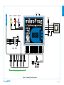
Figure 11-1: GLCD 128x64
connection schematic
SW3
4
5
6
7
P4
8
Connector pinout explained
10K
GLCD BCK PWM
PA2
PA3
PD6
PC0
PC1
PC2
PC3
PC4
PC5
PC6
PC7
PD7
PB0
PB1
20
VCC-5V
VCC-BRD
R34
Q5
BC846
R37
4K7
CN16
GLCD-TFT SOCKET2
CS1 and CS2 - Controller Chip Select lines
VCC - +5V display power supply
GND - Reference ground
Vo - GLCD contrast level from potentiometer P4
RS - Data (High), Instruction (Low) selection line
R/W - Determines whether display is in Read or
Write mode.
E - Display Enable line
D0–D7 - Data lines
RST - Display reset line
Vee - Reference voltage for GLCD contrast
potentiometer P3
LED+ - Connection with the back-light LED anode
LED- - Connection with the back-light LED cathode
20
CS1
CS2
GND
Vcc
Vo
RS
R/W
E
D0
D1
D2
D3
D4
D5
D6
D7
RST
Vee
LED+
LED-
1
R36
1K
Standard and PWM-driven back-light
As for LCD, we have allowed GLCD back-light to be enabled in two
different ways:
1. It can be turned on with full brightness using SW3.1 switch.
2. Brightness level can be determined with PWM signal from the
microcontroller, allowing you to write custom back-light controlling
software. This back-light mode is enabled with SW3.2 switch.
IMPORTANT: In order to use PWM back-light both SW3.1 and SW3.2 switches must
be enabled at the same time.
EasyAVR
v7
page 21