1
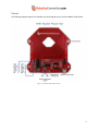
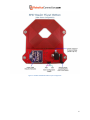
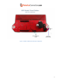
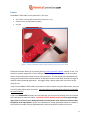
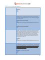
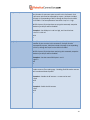
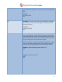
RoboticsConnection.com RedBee™ RFID Reader User Guide 6/10/2010 v1.3 1 Introduction .................................................................................................................................................. 3 Communication Interfaces .................................................................................................................... 3 RFID Reading Range .............................................................................................................................. 3 Input/Output Pin Interfacing ................................................................................................................ 3 Internal Valid Tag List ............................................................................................................................ 4 Autopulse .............................................................................................................................................. 4 Asynchronous Serial Event Notification Packets .................................................................................. 4 Pinout ............................................................................................................................................................ 5 Power ............................................................................................................................................................ 8 Input Power Jumper Configuration........................................................................................................... 9 Communication ........................................................................................................................................... 10 Jumper Configuration ............................................................................................................................. 10 Serial Communication Configuration ...................................................................................................... 10 Protocol Summary ...................................................................................................................................... 11 Commands .............................................................................................................................................. 11 Responses ............................................................................................................................................... 11 RFID Protocol Command Summary ........................................................................................................ 12 Other protocol details ............................................................................................................................. 18 Boot Prompt Format ........................................................................................................................... 18 Asynchronous Packets ........................................................................................................................ 18 SSD Protocol and Broadcast Personal Area Network Mode ................................................................... 20 Terminal Apps: ............................................................................................................................................ 21 RedBee™ RFID Reader .NET Library ............................................................................................................ 24 Installation: ......................................................................................................................................... 24 Documentation: .................................................................................................................................. 24 RedBee™ RFID Reader FAQS ....................................................................................................................... 25 Useful Links: ................................................................................................................................................ 25 Dimensions.................................................................................................................................................. 25 2 Introduction The RoboticsConnection RedBee™ RFID Reader is a sophisticated reader that can work in standalone, or Networked BPAN (Broadcast Personal Area Network) mode. The reader is designed to work with all EM41xx family 125 kHz RFID tags including cards, buttons, capsules, disks, key fobs, and others. Communication Interfaces The RedBee™ reader has a direct USB and wireless XBee serial interfaces. The USB interface simply connects to a host computer using a USB A to Mini-B cable, included with the reader. The XBee wireless serial interface communicates with another XBee module connected to the host computer via a USB Xbee carrier board. The XBee wireless interface is very powerful in that a host computer can communicate with one or more readers, simultaneously, on an XBee Broadcast Personal Area Network (BPAN). This requires some basic XBee configuration of the RFID reader and XBee modules, but is very easy to do. Setup will take a matter of minutes. We will discuss how to configure the RFID readers to communicate in an XBee BPAN scenario later. RFID Reading Range It has an excellent range of 4 ½”, however, this can vary depending on the RFID tag packaging, input voltage, and orientation of the tag when swiped. Also, placing two RedBee™ RFID readers in close proximity (closer than 15” apart), will degrade reading performance. Input/Output Pin Interfacing Care should be taken when interfacing devices to the I/O lines on the RFID reader. The diagram below depicts the various ways in which you can connect switches, LEDs, and relays to the I/O header. 5V 5V 5V 5V 5V Relay LED 1N4148 10K Load 470 RFID Reader Auto Pulse Pins (OUT1, OUT2, OUT3, OUT4) C RFID Reader Auto Pulse Pins Pins (OUT1, OUT2, OUT3, OUT4) B RFID Reader Input Pins (DEL, SAV, RFP, OUT1, OUT2, OUT3, OUT4) 1K 1K Q1 2N3904 E Gnd LED Gnd Figure 1 - RFID Reader Push Button/LED/Relay Interface Schematics 3 Internal Valid Tag List The RedBee™ RFID reader can store up to 48 tags in an internal valid tags list. Tags can be saved/deleted to/from the list either via serial commands, or by pulling the SAVE and/or DEL pins on the reader to ground (see input/output pin interface circuit in the section above for proper switch/push button connection). Autopulse In response to a tag swipe, the RedBee™ RFID reader can respond by automatically pulsing one of the four OUT pins. This ‘autopulse’ functionality allows you to connect up to four relays (for example) to the OUT pins, to activate door locks or other peripherals when a valid tag is swiped. The enabling, direction, and duration of each autopulse pin is fully configurable via serial commands (see input/output pin interface circuit in the section above for proper LED/Relay connection). Asynchronous Serial Event Notification Packets The RedBee™ RFID reader transmits out serial event packets in response to various events, containing data specific to that event and RFID tag id. This allows the host application can decide on the appropriate action to take (e.g. grant access for the tag id swiped), and send a command down to toggle one of the outputs (to unlock a door). Asynchronous packets are sent out for the following events: Tag Swipe Tag Delete (via the DEL pin on the reader) Tag Save (via the SAVE pin on the reader) Pin changes (via the OUTx pins on the reader) RF Power Enable/Disable (via the RFP pin on the reader) This is useful to keep the configuration on the board coherent with host applications that are also communicating with the reader. More detail about the format of the serial event notification packets will be covered in the Protocol section of this document. 4 Pinout The following diagrams depict the available control/configuration pins for the RedBee™ RFID reader. Figure 2 - RedBee™ RFID Reader Pinout 5 Figure 3 - RedBee™ RFID Reader XBee Jumper Configuration 6 Figure 4 - RedBee™ RFID Reader USB Jumper Configuration 7 Power The RedBee™ RFID reader can be powered in 1 of 3 ways: 12V 2.5mm X 5.5mm Barrel connector (Center pin is +V) USB (must use included power jumper) Vcc pins Figure 5 - 2.5mm x 5.5mm Barrel power supply connector (Center pin is +6v to +12V) The Barrel connector allows you to connect generic DC wall type power supplies, rated 6V to 12V. You should use a power supply with a current rating sufficient enough to power the board, XBee modules, and any relays and/or push buttons that you have connected. The board itself pulls about 80mA with nothing connected and the antenna enabled. Disabling the antenna saves about 30mA which might be useful for battery powered applications. We suggest using a power supply with a minimum current rating of 1.0A. If you have the RedBee™ RFID reader connected to the host computer using the USB interface, then you can simply allow USB to power the reader. You must make sure that the power jumper is connected in the position below! If you have a REGULATED 5V power source and Ground, you can connect it directly to the Vcc and Gnd pins respectively to power the reader. PLEASE BE CAREFUL WHEN DOING THIS! If you apply voltages higher than 5V to the Vcc pins, damage will almost certainly ensue! Also, make sure you don’t swap the polarity of the input power! We are not responsible for issuing replacement boards to customers who power their readers using unregulated power, and/or who swap the polarity on the pins! 8 Input Power Jumper Configuration Before you get started attempting to communicate with the RedBee™ RFID reader, ensure that you have power applied properly by placing the power jumper in the correct location. If you are powering via VCC, or Barrel connector, make sure the jumper is removed between VCC and USB V+ pins. Failure to do so might cause power contentions between the input power source, and the USB power source! If you are powering via USB, make sure the jumper is installed between VCC and USB V+. This routes the incoming USB power (via the USB cable) to the other components on the board. 9 Communication Jumper Configuration In order to properly communicate with the RedBee™ RFID reader, you must ensure that you have the serial communication jumper configured properly, according to your desired configuration. This would be either USB or XBee, and is pretty much self explanatory. Serial Communication Configuration The RedBee™ RFID reader comes configured to communicate at 9600 baud, No parity, One Stop bit, and No Flow Control. You can change the baud rate to one of the following values (2400, 4800, 9600, 19200, 57600, 115200) using the ‘cb’ command in the serial protocol, but due to the small amount of traffic sent to/from a reader, you probably won’t have to change it. A baud rate of 9600 is plenty fast enough for any communication to/from the RFID reader. If you must change the baud rate, and you’re using XBee modules, remember to also change the baud rate on the XBee module itself! Failure to do so will prevent proper serial communication to/from the reader. To change the baud rate, send the command ‘cb’ first (along with the proper baud rate), then use Digi XCTU, and a USB Xbee Carrier board to configure the baud rate of the XBee module. More information using Digi X-CTU can be found later in this document. 10 Protocol Summary The RedBee™ RFID Reader features a powerful yet simple serial protocol that customers can leverage in communicating with the board. This section describes the protocol, and how to use it. Commands All commands are terminated by a '\r' character. Specifically, this is the Carriage Return (CR – 0xD) ascii character. This character is invisible to the user typing commands in a terminal, because this character gets appended to the command when you press the 'Enter' key. While we don’t show the ‘\r’ in the examples below, be aware that you must terminate every command with them if you are programmatically sending commands to the reader. Otherwise, the reader will not properly execute the command. Shown below is the proper format for all commands: <command>\r Responses All responses begin with a ‘\r\n’, have the response content, and are terminated with a '\r\n>' character sequence. This makes responses easy to read from within terminal applications. The ‘\r\n’ portion of the sequence will be invisible, but again we’re showing it here for completeness. The ‘>’ character in the return sequence is obviously visible. The response content can be made up of any characters, excluding those mentioned in the special characters section below. Shown below is the proper format for all responses: \r\n<response content>\r\n> For responses that don't return values, then an 'ACK' or 'NACK' is returned to indicate whether the command was executed properly. Also, if a command that typically returns a value, didn’t execute properly (because of an invalid or out of range parameter), then a 'NACK' is returned. Shown below are the valid ACK/NACK responses: \r\nACK\r\n> \r\nNACK\r\n> 11 RFID Protocol Command Summary fw Firmware command: Call to retrieve the internal firmware version. Example 1: >fw 1.0.0 > rst Reset command: Call to reset the RFID Reader. If the boot prompt is enabled (via 'bp'), you will see the boot prompt print out after this command is received (shown below). If it isn't enabled, nothing will print during a reset. Example 1: (boot prompt enabled) >rst #RFIDReader:1:1.0.0:Copyright 2004-2010 RoboticsConnection.com > Example 2: (boot prompt disabled) >rst rtr Restore command: Call to restore the RFID Reader back to factory settings. You are also likely to see a few funny characters print just before the boot prompt once a restore command is executed. Be sure to properly parse for these situations in your applications that might be communicating w/ the reader (if you aren't using our libraries). When you issue a restore command, understand that it resets EVERYTHING, including the internal valid tag list, board id, communications mode, etc. Example 1: >rtr #RFIDReader:1:1.0.0:Copyright 2004-2010 RoboticsConnection.com > cb [0|1|2|3|4|5] Configure Baud Rate command: This configures the baud rate that the RFID Reader is using for serial communications. Please note that if you are using XBee modules, you will have to change the baud rate on those modules to match the baud rate you're setting the RFID reader to here, using X-CTU!!! Otherwise, XBee communication to your board WILL NOT WORK. Example 1: Set the baud rate to 9600 >cb 2 ACK > 12 bp [0|1] Boot Prompt command: Enables/Disables the boot prompt from displaying when the RFID reader boots/powers up, or after a reset or restore. Example 1: Enable the boot prompt >bp 1 ACK > Example 2: Disable the boot prompt >bp 0 ACK > ap [pin:dir:duration] Configure Auto Pulse Parameters command: Configures the autopulse behavior for each individual pin. Autopulse functionality is disabled for an individual pin using the 'sio' command. The pin param can be a value between 1 and 4, corresponding to OUT1, through OUT4 pins on the RFID 2x7 header. The dir (direction) param specifies whether the I/O line goes high (1), or low(0) during a pulse. The duration param specifies for how long (in milliseconds) the pulse lasts for. Durations can range from 0 to 65535. Example 1: Configure autopulse params for pin 1 to go high for 500 milliseconds when a valid tag is swiped. >ap 1:1:500 ACK > Example 2: Configure autopulse params for pin 3 to go low for 4 seconds when a valid tag is swiped. >ap 3:0:4000 ACK > 13 sio [pin:state] Set I/O command: Sets the state of the specified I/O pin to 0 or 1. Any number of <pin:state> pairs can exist in this command. Each <pin:state> pair must be separated by a space. Valid pins include 1 through 4, corresponding to OUT1, through OUT4 pins on the RFID 2x7 header. The state parameter must be 0 = low, or 1 = high. NOTE: Once an I/O pin has been set using this command, autopulse behavior for that pin will be disabled! Example 1: Set GPIO pins 1 and 2 to high, and 3 and 4 to low. >sio 1:1 2:1 3:0 4:0 ACK > gio [pins] Get I/O command: Gets the state of the specified I/O pin. Any number of pins can exist in this command. Each pin must be separated by a space. Valid pins include 1 through 4, corresponding to OUT1, through OUT4 pins on the RFID 2x7 header. NOTE: Once an I/O pin has been read using this command, autopulse behavior for that pin will be disabled! Example 1: Get the state of GPIO pins 1 and 2 >gio 1 2 00 > rfp [0|1] RF Power Enable/Disable command: Enables/Disables the RFID reader antenna from reading tags. Disabling the RFID reader antenna will save about 30mA of power. Example 1: Disable the RF antenna - no tags can be read >rfp 0 ACK > Example 2: Enable the RF antenna >rfp 1 ACK > 14 ls List Tags command: returns a list of currently valid tags saved internally in the reader, each separated by comas. An ACK will indicate the end of the valid tag list. Example 1: List the valid tags currently stored in the valid list >ls 10 124 77 0 98,45 0 188 113 254,112 44 0 55 33,ACK > ctl Clear Tag List command: clears the list of currently valid tags saved internally in the reader. NOTE: Depending on how many tags are currently saved in the internal valid list, it may take a few seconds for this command to execute! So, your host application needs to take this into account. Example 1: >ctl ACK > sv Tag Save command: saves the last tag swiped to the internal valid tag list. If the internal list (of 48) is full, a NACK will be returned. Example 1: >sv ACK > Example 2: Full list! No more room to store more than 48 tags! >sv NACK > del Tag Delete command: deletes the last tag swiped from the internal valid tag list. If there wasn't a tag to delete, a NACK will be returned. Example 1: >del ACK > Example 2: Tag wasn’t previously in valid tag list >del NACK > 15 st Tag Store command: stores the sequence of 5 numbers, identifying a tag, to the internal valid tag list. Each number must be separated by a space. Example 1: >st 10 124 77 0 98 ACK > rm Tag Remove command: removes the tag, identified by the sequence of 5 numbers from the internal valid tag list. Each number must be separated by a space. Example 1: >rm 10 124 77 0 98 ACK > did [id] BPAN DeviceId command: Gets/Sets the RFID reader device id, which can be a value between 1 and 254. This is used when in Xbee BPAN networking mode, and is used to distinguish readers from each other when simultaneously on the network. This device id will be printed in the boot prompt, when the boot prompt is enabled. NOTE: Every reader connected to the XBee BPAN must have a unique device id! Otherwise, multiple devices with the same device id will compete over the BPAN, and WILL cause communication failures! Example 1: Query the device id (factory default is 1). >did 1 > Example 2: Set the device id to 5 >did 5 ACK > 16 xb [0|1] Enable Xbee BPAN Networking command: Puts the reader in XBee BPAN mode. In this mode, the firmware expects commands to come prepended with a “fromdid/todid”, and all responses sent back will have a “todid/fromdid” prepended to them. Please see the XBee BPAN protocol section below for more details. Example 1: Set the Device ID to 5, and enable XBee PAN Networking. NOTE: Once the reader enters XBee networking mode, ALL commands must have the board id prepended to it, and all responses will have the board ids prepended to them. >did 5 ACK >xb 1 ACK > Example 2: Disable XBee PAN Networking. NOTE: Since we were already in XBee networking mode, we had to prepend the “fromdid/todid” to the command, so that reader 5 is the only reader that executes the command. It responds back with a “todid/fromdid” and ACK. >@0/5:xb 0 @5/0:ACK > Ping Ping devices currently connected to the XBee BPAN Network. Any device connected to the XBee BPAN will respond with the following: @<DeviceId>: <Device Name>:<Firmware Version>:<Device Info> Devices calculate a wait time to respond based on their device id, to prevent response collisions over the XBee BPAN network. The calculation is ((DeviceId * 50) + 200) milliseconds. Example 1: Issue a ping request to see devices on the XBee BPAN: >@0:ping @5: #RFIDReader:5:1.0.0:(c)2010 RoboticsConnection.com @7: #RFIDReader:7:1.0.0:(c)2010 RoboticsConnection.com > 17 Other protocol details Boot Prompt Format The format of the boot prompt that prints out when the RFID reader boots up (and ‘bp’ is enabled) is shown below: #<DeviceType>:<DeviceId>:<Firmware Version>:<Device Info String>\r\n> Where: DeviceType is always ‘RFIDReader’ DeviceId is whatever you set it to using the ‘did’ command, in a range of 1 to 254 Firmware Version is self explanatory Device Info String is free-form text that can include copyright information, etc. This allows host computers communicating over the XBee BPAN Network to discover new readers (and other XBee devices for that matter) that come online at run-time. Asynchronous Packets We mentioned a few sections back that the RFID Reader will stream out packets associated with certain Asynchronous events. These include: Tag Swipe Tag Delete (via the DEL pin on the reader) Tag Save (via the SAVE pin on the reader) Pin changes (via the OUTx pins on the reader) RF Power Enable/Disable (via the RFP pin on the reader) Asynchronous Tag Swipe: When someone swipes a tag, the reader will transmit a serial packet using one of the following packet formats: Valid Tag Packet: T:ACK XXX XXX XXX XXX XXX\r\n > Invalid Tag Packet: T:NACK XXX XXX XXX XXX XXX\r\n > 18 If the tag that is swiped has already been stored in the internal valid list, then a Valid Tag Packet will be returned, otherwise and Invalid Tag Packet is returned. Example of valid Tag Packet: T: ACK 128 0 77 43 145\r\n > Asynchronous Tag Delete: When someone triggers the DEL pin on the reader (by pulling it low), and then swipes a tag, the tag is removed from the internal valid list of tags, and the reader will transmit an asynchronous tag delete packet out. If the tag was previously saved in the list, and it gets removed, an ACK Tag Delete packet is transmitted. If the tag wasn’t previously in the list, then a NACK Tag Delete packet is transmitted. Tag Delete ACK Packet: DT:ACK XXX XXX XXX XXX XXX\r\n > Tag Delete NACK Packet (tag wasn’t previously stored in the list): DT:NACK XXX XXX XXX XXX XXX\r\n > Asynchronous Tag Save: When someone triggers the SAVE pin on the reader (by pulling it low), and then swipes a tag, the tag is added to the internal valid list of tags, and the reader will transmit an asynchronous tag save packet out. If the tag was previously saved in the list, an ACK is returned, but there won’t be duplicated entries. If the valid tag list is full, then a NACK Tag Save packet is transmitted. Tag Save ACK Packet: ST:ACK XXX XXX XXX XXX XXX\r\n > Tag Save NACK Packet (internal valid list was full): ST:NACK XXX XXX XXX XXX XXX\r\n > 19 Asynchronous Pin Changes: When one of the four OUTx pins are used as inputs, and the reader detects that the state of the pin has changed, the reader will transmit an asynchronous pin changed packet out. The packet includes the pin id that changed, as well as the value that it changed to, 0 or 1. Pin Changed Packet: X:<PinId>:<value> \r\n > Asynchronous RF Power Enable/Disable: When the reader detects that the RFP pin has changed state(by pulling it low), it will transmit an asynchronous RF Power Packet out. The packet is identical to the Pin Changed Packet, but the Pin Id is always ‘P’. The state of the RFP power is returned in the packet as a value of 0 or 1, signifying disabled and enabled respectively. RF Power Enable/Disable Packet: X:P:value> \r\n > SSD Protocol and Broadcast Personal Area Network Mode Since Xbee modules support broadcast communications using the Broadcast Personal Area Network (BPAN), we decided to take advantage of it, and develop a protocol that wraps the RedBee™ RFID Reader protocol, and allow customers to communicate with multiple readers, simultaneously, using a single serial port. We call this protocol the Shared Serial Device protocol, or SSD protocol. This protocol was generically designed to be leveraged by any device retrofitted with an XBee module, and isn’t limited to just a RedBee™ RFID reader. In fact, we’ll be using the SSD protocol in our Serializer product line very soon! Because this is a generic protocol that can be used by many devices, we decided to describe it in its very own document, which can be found here: http://www.roboticsconnection.com/multimedia/docs/RFID/SSDprotocol.pdf 20 Terminal Apps: We believe the best, free terminal application available today is PuTTY. If you wish to communicate with the RFID reader over USB or XBee, then this is the app that you'll want to use. PuTTY is a free implementation of Telnet and SSH for Win32 and Unix platforms, along with an xterm terminal emulator. It is written and maintained primarily by Simon Tatham. To use Putty, all you have to do is download it, configure a couple of screens, and you’ll be communicating with the RedBee™ RFID Reader! Once you open PuTTY, you will receive the following screen: Make sure you ‘uncheck’ the checkbox that says ‘Always ask before opening this file, so that you don’t get this dialog box every time to start PuTTY. 21 First, click on the ‘Terminal category, and then under ‘Line Discipline Options’, select: Local echo -> Force on Local line editing -> Auto 22 Next, you’ll want to click on the ‘Session’ category, and then: Select ‘Serial’ destination Enter the COM port you will be communication over (COM11 in the example) Enter the baud rate you will be using (9600 is the default for the RedBee RFID Reader) Type ‘RedBee RFID Reader’ in the ‘Saved Sessions’ text box, and then click ‘Save’. Now, simply click ‘Open’ at the bottom, and PuTTY will open in a terminal window. Make sure you have power applied to the RedBee™ RFID Reader, and hit ‘return’ a couple of times. You should see a few ‘NACKs’ appear, followed by the serial command prompt from the RedBee™ RFID Reader. You can now invoke the RedBee™ RFID Reader serial commands at leisure, which were defined in the previous sections of this manual. Below we have used Putty to issue a ‘fw’ and ‘rst’ command to the RedBee™ RFID Reader. 23 RedBee™ RFID Reader .NET Library We provide a .NET library and User documentation for this product which implements the protocol defined above, and allows you to work with this reader using objects. You can develop applications in any .NET language, but we only supply examples in C# and VB.NET. Installation: Please follow the installation guide below for proper installation and usage: http://www.roboticsconnection.com/multimedia/docs/RFID/RFIDDotNetLibInstallationGuide.pdf Documentation: Additionally, we provide extensive documentation and examples for the RedBee RFID Reader here: http://www.roboticsconnection.com/multimedia/libraries/RFID/documentation/ 24 RedBee™ RFID Reader FAQS RF Range will decrease with insufficient power supply. So if you have a battery as a power source, and you’re having difficulties with the reader picking up tags, this is probably the problem. RF Range will substantially decrease if you place two RedBee™ RFID readers in close proximity (closer than 15 inches between each reader). If you have set up one of the OUTx pins as an output, subsequent reads will not return accurate readings. Store the output state that you set last if you wish to remember it in your host application. Useful Links: JAMECO RELIAPRO TRANS,WALL,12VDC/1.0A,F2, 2.5mm X 5.5mm Electrical Wall Plate Push Button I/O Board that easily interfaces to RedBee™ RFID reader Dimensions Below are the overall dimensions of the RFID Reader to aid in mounting it in/on/to your project. 25