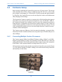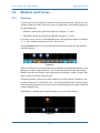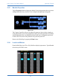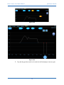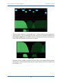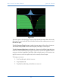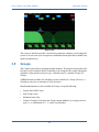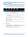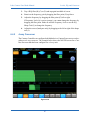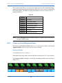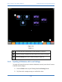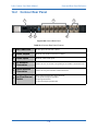
1
Lake Contour User Mode Manual
Release Date: August 2003
Document Version: 1.1
Part Number: DOC-532-0005-01
www.contour.lake.com
Important Safety Instructions and Warnings
Standards Compliance
This product has been certified to comply with:
•
Safety
UL6500, EN 60065, CB scheme.
•
EMC
FCC part 15 Class A
And carries the CSA mark and FCC required marking.
NOTE: This equipment has been tested and found to comply with the limits for a Class
A digital device, pursuant to Part 15 of the FCC Rules. These limits are designed to provide reasonable protection against harmful interference when the
equipment is operated in a commercial environment. This equipment generates, uses, and can radiate radio frequency energy and, if not installed and
used in accordance with the instruction manual, may cause harmful interference to radio communications. Operation of this equipment in a residential
area is likely to cause harmful interference in which case the user will be required to correct the interference at his own expense.
Explanation of Symbols
These symbols are internationally accepted symbols that warn of potential hazards with
electrical products.
The lightning flash in an equilateral triangle alerts the user to the presence of uninsulated “dangerous voltage” within the product enclosure
that may be of sufficient magnitude to constitute a risk of electric shock.
The exclamation mark in an equilateral triangle alerts the user to the presence of important safety, operating or maintenance (servicing) instructions in the literature accompanying the appliance.
Safety Instructions
1.
Read these instructions.
2.
Keep these instructions.
3.
Heed all warnings.
4.
Follow all instructions.
5.
Do not use this apparatus near water.
6.
WARNING! To reduce the risk of fire or electric shock, do not expose this apparatus to rain or moisture.
7.
Clean only with dry cloth.
8.
Do not block any ventilation openings. Install in accordance with the manufacturer’s instructions.
9.
Do not install near any heat sources such as radiators, heat registers, stoves, or
other apparatus (including amplifiers) that produce heat.
10. Warning! This is a Class 1 device. The electrical safety design of Class 1 devices depends on proper grounding. To maintain electrical safety ensure that a
grounded mains lead is used and that it is properly connected to a grounded
mains wall outlet.
11. Do not defeat the safety purpose of the polarized or grounding-type plug. A polarized plug has two blades with one wider than the other. A grounding type
plug has two blades and a third grounding prong. The wide blade or the third
prong are provided for your safety. If the provided plug does not fit into your
outlet, consult an electrician for replacement of the obsolete outlet.
12. Protect the power cord from being walked on or pinched particularly at plugs,
convenience receptacles, and the point where they exit from the apparatus.
13. Only use attachments/accessories specified by the manufacturer.
14. Unplug this apparatus during lightning storms or when unused for long periods
of time.
15. WARNING! Refer all servicing to qualified service personnel. Servicing is required when the apparatus has been damaged in any way, such as power-supply
cord or plug is damaged, liquid has been spilled or objects have fallen into the
apparatus, the apparatus has been exposed to rain or moisture, does not operate
normally, or has been dropped.
16. WARNING! To reduce the risk of electric shock, DO NOT REMOVE COVER.
No user serviceable parts inside.
Contour Warranty Statement
Lake warrants that Lake Contour hardware will be free from defects in components and
workmanship for a period of 12 months from the date of invoice. During the warranty
period, Lake will cover the cost of all parts and labour to remedy the defect, or replace
products which prove to be defective. If the hardware is found by Lake to be defective
and needs to be serviced off site Lake will pay reasonable freight charges. Lake is not
obliged to honour this warranty if the hardware has failed to be maintained and operated
as specified by Lake, in the accompanying documentation, or other than in accordance
with industry standards. Defects caused by unauthorized modifications, misuse, negligence,
act of God or accident are not covered by this warranty. This Limited Warranty is exclusive and no other warranty is expressed or implied. Lake does not warrant that Lake
software, or any third-party software, is error free. Third party branded or manufactured goods are supplied by Lake with care but without responsibility and subject
only to third party suppliers’ warranties. In all other respects Lake is not liable for consequential damages.
Lake Contour User Mode Manual
Table of Contents
Chapter 1: Introduction .................................................................................................11
Chapter 2: Hardware Setup and Software Installation.................................13
2.1
Hardware Requirements ..........................................................................13
2.1.1
2.1.2
2.1.3
Minimum Hardware Specifications ..........................................13
Recommended Hardware Specifications ..................................13
Video Card Settings ..................................................................14
2.2
Software installation................................................................................14
2.3
Network Configuration............................................................................15
2.4
Hardware Setup .......................................................................................19
2.4.1
2.4.2
2.4.3
Connecting Multiple Contour Processors .................................19
Wired Network Setup................................................................20
Wireless Network Setup............................................................23
Chapter 3: Quickstart Tutorial ...................................................................................25
3.1
Introduction .............................................................................................25
3.1.1
3.1.2
3.2
Modules and Frames................................................................................27
3.2.1
3.2.2
3.2.3
3.2.4
3.3
Starting the Controller for the first time....................................25
Basic Navigation .......................................................................25
Overview...................................................................................27
Labeling Frames and Modules..................................................29
Module Properties .....................................................................31
Levels and Meters .....................................................................31
EQ............................................................................................................33
3.3.1
3.3.2
3.3.3
3.3.4
3.3.5
Graphic EQ ...............................................................................33
Ideal Graphic EQ ......................................................................34
Parametric EQ ...........................................................................36
Add a New EQ Overlay ............................................................38
Mesa Filter ................................................................................38
3.4
Crossovers ...............................................................................................42
3.5
Groups .....................................................................................................45
v
Lake Contour User Mode Manual
3.5.1
3.5.2
Assigning Modules to a Group .................................................46
Assigning Meters at Group Level .............................................47
3.6
Contour File Types ..................................................................................48
3.7
Technical Support Information................................................................50
Chapter 4: System Store and Recall ......................................................................51
4.1
Recall / Open ...........................................................................................51
4.2
Recall Compare .......................................................................................52
4.3
Store.........................................................................................................52
4.4
New Store ................................................................................................53
4.5
File Utilities .............................................................................................53
4.5.1
4.5.2
4.5.3
4.5.4
4.5.5
Open ..........................................................................................53
Read Only .................................................................................53
Rename......................................................................................53
Delete ........................................................................................54
New Folder................................................................................54
Chapter 5: Modules ..........................................................................................................55
5.1
EQ/Levels ................................................................................................55
5.2
Properties.................................................................................................56
5.2.1
5.2.2
5.2.3
5.2.4
5.2.5
5.3
Label & Lock...........................................................................................58
5.3.1
5.3.2
5.3.3
5.3.4
5.3.5
5.3.6
5.4
Update ARM .............................................................................57
Update DSP...............................................................................57
Clear Counters...........................................................................57
Factory Reset ............................................................................58
Update Arm Boot ......................................................................58
Label Module ............................................................................58
Label Frame ..............................................................................58
Unlock Module .........................................................................59
Set Password (for Module) .......................................................59
Unlock Base ..............................................................................59
Set Password (for Base Configuration).....................................59
Copy/Paste/Replace.................................................................................59
vi
Lake Contour User Mode Manual
5.4.1
5.4.2
5.4.3
5.4.4
Copy ..........................................................................................60
Paste ..........................................................................................60
Replace Frame/Label ................................................................60
Complete Replace .....................................................................61
5.5
Remove....................................................................................................61
5.6
Module Store/Recall................................................................................62
5.6.1
5.6.2
5.6.3
5.6.4
5.6.5
5.7
Recall/Open...............................................................................62
Store ..........................................................................................63
New Store..................................................................................63
Base Configuration ...................................................................63
File Utilities...............................................................................64
Add Page .................................................................................................65
Chapter 6: Levels, EQ, and Crossover .................................................................66
6.1
Overview .................................................................................................66
6.1.1
6.1.2
6.1.3
6.1.4
6.2
Levels ......................................................................................................68
6.2.1
6.2.2
6.2.3
6.2.4
6.2.5
6.2.6
6.2.7
6.2.8
6.2.9
6.3
General Access..........................................................................66
Restricted Access ......................................................................66
Group Updates ..........................................................................67
Default Settings.........................................................................67
Overview...................................................................................68
Gain...........................................................................................70
Delay .........................................................................................70
Limiter MaxRMS......................................................................70
Limiter Corner...........................................................................71
SoftClamp Level .......................................................................71
SoftClamp Corner .....................................................................71
Headroom/Amp Clip.................................................................71
Meter Options ...........................................................................72
EQ............................................................................................................74
6.3.1
6.3.2
6.3.3
6.3.4
Default Overlays .......................................................................74
Hidden Overlays .......................................................................75
Parametric EQ Screen ...............................................................75
Graphic EQ Screen....................................................................78
vii
Lake Contour User Mode Manual
6.3.5
6.3.6
6.3.7
6.3.8
6.3.9
6.3.10
6.3.11
6.3.12
6.4
Crossovers ...............................................................................................84
6.4.1
6.4.2
6.4.3
6.4.4
6.4.5
6.4.6
6.4.7
6.4.8
6.4.9
6.4.10
6.5
Overlay Functions .....................................................................79
Overlay Bypass/Insert ...............................................................81
Overlay Flat...............................................................................82
Filter Bypass/Insert ..................................................................82
Filter Flat...................................................................................82
Filter Delete...............................................................................82
Filter Edit ..................................................................................82
High-Precision Filter Adjustments............................................83
Using PEQ Filters on the XOVER Screen................................86
4-way Crossover .......................................................................87
Crossover Select/Alignment Delay ..........................................88
Crossover Set ............................................................................89
Crossover Toggle ......................................................................89
Crossover Split/Combine ..........................................................89
Filter Flat...................................................................................90
Filter Delete...............................................................................90
Filter Edit ..................................................................................91
Crossover Properties / High Pass Enable..................................91
Output EQ – Using Contour without Crossovers ....................................92
6.5.1
6.5.2
6.5.3
6.5.4
Configuring a Contour Module for Output-Specific EQ ..........92
Adding Output-Specific EQ......................................................93
High- and Low-Pass Filters.......................................................95
Output EQ Menu Options .........................................................97
Chapter 7: Groups ............................................................................................................99
7.1
EQ/Levels ................................................................................................99
7.2
Assign ....................................................................................................100
7.2.1
7.3
Copy/Paste.............................................................................................101
7.3.1
7.3.2
7.3.3
7.4
Label........................................................................................101
Copy ........................................................................................101
Paste ........................................................................................101
Remove ...................................................................................102
Add Page ...............................................................................................102
viii
Lake Contour User Mode Manual
Chapter 8: Solo/Mute ....................................................................................................103
8.1
EQ/Levels ..............................................................................................103
8.2
Solo/Mute Enable ..................................................................................103
8.3
Pile ........................................................................................................104
8.4
All Mute.................................................................................................104
Chapter 9: Icon Control ...............................................................................................105
9.1
Meters On/Off .......................................................................................105
9.2
Icon Small..............................................................................................105
9.3
Icon Normal...........................................................................................106
9.4
Icon Medium .........................................................................................106
9.5
Icon Large..............................................................................................106
Chapter 10: User Preferences ....................................................................................107
10.1
EQ Preferences ......................................................................................107
10.1.1
10.1.2
No EQ Scale............................................................................107
EQ ±30 dB ..............................................................................107
10.2
Designer Mode ......................................................................................107
10.3
Change Password...................................................................................108
10.4
Global Access........................................................................................108
10.5
About .....................................................................................................108
10.6
Show Frame Rate .................................................................................108
10.7
Show Mode............................................................................................108
Chapter 11: Pages .............................................................................................................109
11.1
Cut Icon .................................................................................................109
11.2
Copy Icon ..............................................................................................109
11.3
Paste Icon...............................................................................................110
11.4
Page Label .............................................................................................110
ix
Lake Contour User Mode Manual
11.5
Page Delete............................................................................................110
11.6
Add Page ...............................................................................................110
11.7
Scrolling Pages ......................................................................................110
Chapter 12: Network ........................................................................................................111
Chapter 13: Communication and Synchronization ........................................113
13.1
Communication .....................................................................................113
13.1.1
13.1.2
13.1.3
13.2
Local/Remote Settings ............................................................113
Offline Modules ......................................................................113
Communication/Network Errors.............................................114
Synchronization.....................................................................................114
13.2.1
13.2.2
13.2.3
13.2.4
Re-Sync Process......................................................................114
Out of Sync .............................................................................115
Updating all Modules with Local Settings..............................116
Synchronizing the Contour Controller and Processors ...........117
13.2.5
Audible Changes when Synchronizing ...................................118
Chapter 14: Front and Rear Panel Reference ....................................................119
14.1
Contour Front Panel ..............................................................................119
14.2
Contour Rear Panel................................................................................120
Chapter 15: Specifications ...........................................................................................121
x
Lake Contour User Mode Manual
Chapter 1: Introduction
Thank you for purchasing the Lake ContourTM Processor for live sound! The Lake
Contour revolutionizes how artists, audiences, and engineers experience live audio.
Lake’s signal processing expertise has produced a revolutionary digital processor that
optimizes live sound in entirely new ways. The Contour has more in common with the
mastering processors found in professional studios than the equalizers and crossovers
typically used for live sound.
The Contour is a two-input, six-output DSP loudspeaker controller that utilizes extended precision 40-bit floating-point math to implement its crossovers, dynamics, delay,
and equalization functions. The Contour Controller software runs on a Windows (98,
2000, ME, and XP) PC. The Contour’s innovative Ethernet-based network design provides a wireless touchscreen interface that delivers commands from the Contour Controller to each Contour Processor. This allows the engineer to listen and adjust any
parameter of any Contour on the Ethernet network from any location in the venue.
The Contour’s most significant features are:
•
State-of-the-art filter synthesis technique allows unlimited number of EQ layers.
•
Unique Mesa Filter.
•
Extensive selection of linear phase, traditional, and non-traditional crossover filters.
•
Wireless touchscreen control enables adjustment from any position in the venue.
•
3-position ground-lift switch provides unparalleled external noise rejection.
•
40-bit floating-point precision throughout entire signal processing path.
•
24-bit/96-kHz Converters.
11
Lake Contour User Mode Manual
Chapter 2: Hardware Setup and
Software Installation
2.1
Hardware Requirements
A Contour Processor must be connected to a Windows PC running the Contour Controller software to enable control and communication.
2.1.1
Minimum Hardware Specifications
These are the minimum specifications for the computer running the Contour Controller
software:
•
400 MHz Pentium III or equivalent
•
64 MB RAM
•
4 MB Video RAM
•
Windows 98 SE, 2000, XP
•
DirectX 8.1 or higher
•
10BaseT Wired Ethernet Adapter and/or 802.11b WiFi wireless Ethernet Adapter
Wireless networking requires the Contour Wireless Package or equivalent.
2.1.2
Recommended Hardware Specifications
These are the recommended specifications for the computer running the Contour Controller software:
•
600 MHz Pentium III or equivalent
•
128 MB RAM
•
8 MB Video RAM
•
Windows 2000 Service Pack 2
•
DirectX 8.1 or higher
•
10BaseT Wired Ethernet Adapter and/or 802.11b WiFi wireless Ethernet Adapter
Wireless networking requires the Contour Wireless Package or equivalent.
13
Lake Contour User Mode Manual
2.1.3
Hardware Setup and Software Installation
Video Card Settings
It is important that the video card is setup correctly to ensure smooth operation of the
Contour Controller. Incorrect video card settings may result in problems or unusual behavior of the graphics display on the Controller.
These are mandatory settings for the Contour Controller video card:
•
minimum monitor display resolution: 800 x 600 pixels
•
color: 16-bit
These are recommended settings for the Contour Controller video card:
•
2.2
3D acceleration: set for best performance with anti-aliasing turned off
Software installation
We recommend exiting all Windows programs before running the Contour Controller
Setup program.
To install the Contour Controller software either:
•
Insert the CD-ROM provided. The Setup program runs automatically.
•
Double-tap the Contour Controller Setup.exe program icon if installing via network or download.
The Contour Controller Setup program will guide you through software installation.
1.
Read or enter information as required and tap Next to proceed
2.
Tap Install when requested.
3.
Tap Finish when installation is complete.
Following successful installation, the Lake Contour Controller icon appears
on the desktop.
Before starting the Contour Controller software, follow the procedures described in
Section 2.3 Network Configuration and Section 2.4 Hardware Setup.
14
Lake Contour User Mode Manual
2.3
Hardware Setup and Software Installation
Network Configuration
The network card of the Contour Controller host computer must be configured properly
in order to communicate with Contour Processors on the network. A valid IP address,
required for network communication between the Contour Controller software and
Contour Processors, can be acquired in numerous ways depending on the network configuration.
If connecting the Contour Controller host computer and Processors to an existing TCP/
IP based Ethernet network, the IP address settings probably do not need to be changed.
If you are unfamiliar with TCP/IP and Ethernet networks, consult with your network
administrator before changing your IP address settings.
If creating a network by connecting only the Contour Processors and the Controller host
computer together, make sure the host computer has a valid IP address. Specify the host
computer’s IP address by following these steps:
1.
Open Network Connections from the Windows Start menu.
The method varies with different versions of Windows but you can usually select Settings->Network Connections.
Figure 2-1
2.
Double click on the appropriate network connection to configure (i.e., Local
Area Connection or Wireless Network Connection.)
NOTE: Although this tutorial uses Local Area Connection as an example, the principles also apply to Wireless Network Connection.
15
Lake Contour User Mode Manual
Hardware Setup and Software Installation
Figure 2-2
3.
Select Internet Protocol (TCP/IP) and click the Properties button.
Figure 2-3
16
Lake Contour User Mode Manual
4.
Hardware Setup and Software Installation
By default, Windows automatically obtains an IP address. You must change
this default selection to specify an IP address. We recommend setting your IP
address to be a part of the 10.xxx.xxx.xxx subnet (i.e., 10.0.0.10).
Figure 2-4
17
Lake Contour User Mode Manual
Hardware Setup and Software Installation
Figure 2-5
5.
Click OK to apply changes and exit Internet Protocol (TCP/IP) Properties.
6.
Click OK to apply changes and exit Local Area Connection Properties.
NOTE: The actual IP address assigned to the Contour Controller host computer is not
important because the Contour system communicates using UDP messaging,
which broadcasts network messages to all nodes on the network. Each node
on the network must be assigned a valid IP address. You can specify any required IP address for other Ethernet network related communications.
When finished with IP address configuration, continue to Section 2.4 Hardware Setup.
18
Lake Contour User Mode Manual
2.4
Hardware Setup and Software Installation
Hardware Setup
Begin setup by connecting the Contour Processor to an AC power source. The unit operates normally if the AC line voltage is within the range 100–240 VAC (±10%) as the
power supply is autoranging (i.e. it detects the AC power present and adjusts internally). Therefore, the Contour Processor can be used anywhere in the world without manually changing switch settings.
The first time the Contour is turned on, it operates in its default configuration (generic
stereo three-way crossover) with crossover frequencies set at 250 Hz and 1.6 kHz. If
the Contour has already been configured, it powers up to the settings last used prior to
being shut down. All parameters are stored in non-volatile memory so if the Contour loses power during operation, it returns to its exact state prior to the loss of power. If a network communication problem occurs, the sound output from the Contour Processors
continues without interruption.
The Contour system uses Ethernet, a local area network technology, to transmit information between the Controller and Processors at speeds of up to 10 million bits per second (10 Mbps).
2.4.1
Connecting Multiple Contour Processors
The Contour supports 10Base2 and 10BaseT Ethernet cabling. 10Base2 is a 10 MHz
Ethernet system running over thin, 50 Ω, baseband, coaxial cable (thin coax). Thin coax
cabling looks like the coaxial cable commonly used to connect test or video equipment.
Each 10Base2 cable segment should be no longer than 185 m (607 ft).
50 Ω terminators must be placed on the start and end of any thin coax network (Figure
2-6). The primary benefits of 10Base2 cabling are its robust metal locking connectors
and immunity to node failure.
Figure 2-6
19
Lake Contour User Mode Manual
Hardware Setup and Software Installation
10BaseT is a 10 MHz Ethernet system running over unshielded, twisted-pair cabling. 10BaseT cabling looks like an ordinary telephone cable but has eight wires instead of four.
Each 10BaseT cable segment should be no longer than 100–150 m (328–492 ft); the
wide range depends on the cable quality. 10BaseT cabling is available in five different
categories: Cat1–Cat5. The quality of the cable increases with the numeric suffix. Do not
use Cat1 or Cat2 cable because their performance cannot be guaranteed to meet the
demands of 10 MHz Ethernet. Cat3–Cat5 are acceptable for Contour systems.
Each Contour contains an Ethernet hub that allows multiple connections between each
Contour Processor and the Ethernet network. The Ethernet hub regenerates and re-times
the signal between each hub port. 10BaseT and 10Base2 Ethernet segments may be used
together through the hub connections on each Contour Processor.
NOTE: When using 10BaseT to network multiple Contour Processors, each Processor in the network must be turned on for network signals to pass. 10Base2
passes network signals whether or not any of the Contour Processors are
turned on. 10BaseT allows cascading four units together; 10Base2 allows cascading 30 units.
2.4.2
Wired Network Setup
The Contour Controller PC can be connected directly to any Contour Processor through
either its front or rear panel Ethernet connectors. Multiple Processors can be connected
by cascading connections between units.
The hardware can be interconnected as a wired or wireless network. The wired network
is a simpler solution and should be implemented before using a wireless system.
Figure 2-7
Figure 2-7 shows the Contour Controller directly connected to a Contour Processor
through the front panel Ethernet port.
20
Lake Contour User Mode Manual
Hardware Setup and Software Installation
Use the PC and Uplink Ethernet ports on the rear panel (Figure 2-8) to network multiple
Contour processors:
1.
Connect the Uplink port of one Processor to the PC port of the next Processor.
2.
Repeat this interconnection method until all Processors intended for the network are connected.
Figure 2-8
3.
Connect the Contour Controller to any available PC port on either the front or
rear panel of a Processor.
The Contour Controller can connect anywhere on a network of multiple Contour
Processors. LEDs above each port flash to confirm valid communication.
Figure 2-9 shows a system using a mix of 10Base2 and 10BaseT cabling.
Figure 2-9
21
Lake Contour User Mode Manual
Hardware Setup and Software Installation
Verifying Controller and Processor Communication
Once the network is connected, follow the steps below to confirm communication between the Contour Controller and Contour Processors.
1.
Double-tap the Lake Contour Controller shortcut icon from the Windows
desktop.
The Select Network Adapter dialog (Figure 2-10) appears if your computer
has more than one network interface enabled. This typically occurs if your PC
has both wired and wireless network interfaces.
2.
Select the Ethernet adapter currently used for the Contour network (the wired
adapter for this example).
Figure 2-10
3.
Tap No in the dialog that appears asking whether to recall the last configuration.
The Main page of the Contour Controller is displayed.
4.
To verify that the Contour Processors are on the network and communicating,
tap the Modules button.
The Module Scroll Bar appears.
Figure 2-11
22
Lake Contour User Mode Manual
Hardware Setup and Software Installation
The first Module from the left in the Module Scroll Bar is the Dummy Module, which
is always available whether the network is operating properly or not. If your network
connections are correct, all Contour Processors currently connected to the network appear in the Module Scroll Bar to the right of the Dummy Module. In Figure 2-11, the A
and B Modules are in a Frame that represents one Contour Processor connected to the
network. See Modules and Frames on page 27 for more information.
If you are not planning to use wireless connectivity, proceed to Chapter 3: Quickstart
Tutorial.
2.4.3
Wireless Network Setup
Before setting up a wireless network for the first time, we recommend verifying system
operation by connecting one of the wired networks described in the previous section.
When the Contour Controller and Processors are communicating on a wired network,
close the Contour Controller program:
1.
From the Home menu, tap Quit Controller.
2.
Tap Yes on the warning message to confirm the action.
Several hardware manufacturers supply wireless networking solutions that adhere to
the same 802.11b wireless Ethernet standard used in the Contour system. This means
that any 802.11b wireless networking solution should work. However, after extensive
testing of available wireless networking solutions, we have found that performance varies tremendously among vendors. Lake provides its own wireless networking package
for the Contour system that works straight out of the box.
NOTE: Although the following instructions are specific to the Contour wireless networking package, the majority of concepts and terminology translate directly
for other 802.11b solutions.
An access point is used in a wireless Ethernet network configuration to connect Contour Processors to the Contour Controller host computer. An access point looks like an
external modem with two small antennae. This radio-based receiver/transmitter is connected to your wired LAN using network cables. It performs the same function as a
switch: receiving, buffering, and transmitting data between wired and wireless networks. Contour Processors are wired just like a wired network (see Connecting Multiple Contour Processors on page 19).
1.
Connect an available Ethernet port on a Contour Processor to the access point.
2.
The Contour Controller host computer must also have a wireless Ethernet network interface card; this is usually included in tablet PCs.
Figure 2-12 illustrates the wireless configuration.
23
Lake Contour User Mode Manual
Hardware Setup and Software Installation
Figure 2-12
Ideally, the procedure described above yields a perfectly functional and secure system.
However, there are two complications:
•
Some environments have additional wireless network systems and communications
equipment competing for the same airspace used by the Contour system.
•
It is also important to provide security so another wireless network cannot access
the Contour network.
As part of the 802.11b standard, various levels of access control and encryption exist.
There are also different communication channels that operate at different frequencies.
The Service Set Identifier (SSID) controls access to the Contour wireless network by
functioning as a password or key between wireless network devices to differentiate
them from each other. The SSID must be exactly the same on all wireless devices (i.e.,
the access point and all Contour Controller host computers). The SSID is case-sensitive.
Although the SSID differentiates among wireless systems, it does not provide security
to the network. Wired Equivalent Privacy (WEP) is a security protocol for wireless networks defined in the 802.11b standard. WEP provides the same level of security as a
wired network by encrypting data over radio waves to protect it during transmission.
The Contour Wireless Package sets the SSID for you. The SSID is set to
LakeCTR5253_XXXX, where XXXX is a unique number to your wireless access package.
WEP encryption is not enabled. This should only be necessary if you plan on using an
existing LAN that includes sensitive information. We recommend that WEP encryption
be enabled if any other computers are connected to your Ethernet network.
Refer to the Lake Contour Wireless Access Package User Guide for further details.
24
Lake Contour User Mode Manual
Chapter 3: Quickstart Tutorial
This Quickstart Tutorial will help you begin using the Contour Controller software
quickly and easily by providing a cursory overview of its most commonly utilized features. There are many underlying details that are not covered in this Quickstart Tutorial.
For more detailed information, please refer to the Lake Contour User Guide on the Lake
Contour CD.
The tutorial examples will guide you through some basic setup procedures. You must
have at least one Contour Processor connected to the Contour Controller host computer
to proceed with this tutorial (see Chapter 3: Quickstart Tutorial).
3.1
Introduction
3.1.1
Starting the Controller for the first time
1.
Double-Tap the Lake Contour Controller software icon located on the Windows desktop.
2.
Tap No in the dialog asking if you would like to recall the last configuration.
Tapping Yes loads the last configuration used but this is not desirable since we
are starting for the first time.
The Main Page appears blank.
3.1.2
Basic Navigation
The Button Bar, located at the bottom of the every page in the software, is used to navigate through and activate the Contour Controller’s features and functions. Three colors
indicate the button’s status:
•
Orange: Currently selected menu or function
•
Blue: Available menu or function based on current selection
•
Gray: Currently unavailable menu or function
The Home button (highlighted in Figure 3-1) is always available and returns you to the
Main Page.
Figure 3-1
25
Lake Contour User Mode Manual
Quickstart Tutorial
The label on each button describes the sub-menu opened or the function performed by
tapping the button.
Context-sensitive help and system status messages are displayed above the Button Bar
on the left and right of the screen, respectively.
To minimize the Contour Controller and return to Windows, tap the Contour Icon in the
top-right corner of any screen.
Figure 3-2
26
Lake Contour User Mode Manual
Quickstart Tutorial
3.2
Modules and Frames
3.2.1
Overview
A Frame represents one physical Contour Processor on the network. Two Modules are
available within one Frame. In a stereo crossover application, each Module operates as
an independent unit:
•
Module A controls the signal from Input A to Outputs 1, 2, and 3.
•
Module B controls the signal from Input B to Outputs 4, 5, and 6.
For a mono 4-way crossover, both Modules process the signal from Input A to Outputs
1, 2, 3, and 4. Input B and Outputs 4 and 5 are not used.
Tap the Modules button to see the Contour Processors on the network; the Modules
Scroll Bar appears.
Figure 3-3
With one Contour Processor on the network, the Module Scroll Bar displays three icons
that represent three Contour Modules. The first Module from the left is the Dummy
Module, the other two Module icons represent the two Modules within a Frame of the
single Contour Processor on the network.
A Dummy Module is always accessible whether or not the Contour Controller is connected to a network of Contour Processors. The Dummy Module allows off-line adjustment of Module parameters so an entire system can be designed, then replaced with real
Contour Modules later.
Tap Module A, and then tap on the Main Page where you wish to place it.
Figure 3-4
27
Lake Contour User Mode Manual
Quickstart Tutorial
The Contour Processor synchronizes itself with the Contour Controller. During the synchronization process, the Contour Controller gathers current settings for both Modules
from the Contour Processor. Once a Module is placed on the Main Page and synchronized, the Contour Controller has full control and access to the Module.
Place the Module B on the Main Page. No synchronization is required this time because
the information for both Modules was obtained when Module A was placed.
Each Module icon provides the following configuration information:
Module ID
Frame Label
Crossover Type
Input Mute Indicator
Module Label
Output Mute Indicators
Figure 3-5
•
Module ID: Identifies the Module of the Contour Processor represented by this
icon.
•
Frame Label: Identifies the Frame associated with this icon by a four-character
user-defined label that also appears on the front panel of the Contour Processor.
•
Crossover Type: Identifies the number of outputs provided by this crossover (2-,
3-, or 4-way).
•
Module Label: A user-defined label that describes the Module’s use or speaker
type.
•
Input Mute Indicator: If the central round part of the icon is red (as shown above),
the input is muted; if the icon is blue, the input is not muted.
•
Output Mute Indicators: These display as small red bars when the outputs are
muted and are absent if unmuted. The number of mute indicators depends on the
number of output channels in the selected crossover type.
Each Contour Processor is shipped with a default configuration that provides a 24 dB
per octave Linkwitz-Riley three-way crossover with frequencies centered at 250 and
1600 Hz. This default configuration sets the Module Label to XOVR1.
28
Lake Contour User Mode Manual
3.2.2
Quickstart Tutorial
Labeling Frames and Modules
The Frame Label is blank in the Contour Controller as well as on the front panel of the
Contour Processor.
To name the Frame, tap one of the Modules to select it. Selection is indicated by a yellow border surrounding the Module icon.
Figure 3-6 Module Not selected (left); Module Selected (right)
If a Module is not selected, most of the Button Bar functions are gray to signify they
are inactive.
1.
Tap Label & Lock.
2.
Tap Label Frame to display the onscreen keyboard.
Figure 3-7
3.
Type Demo and tap OK.
You can also use a manual keyboard if attached to your computer.
Figure 3-8 shows that the Contour Processor’s alphanumeric display now shows
DEMO. The alphanumeric display always shows capital letters so it can be seen from a
longer distance. The Frame Label field for both Modules also displays Demo in the
Contour Controller software.
29
Lake Contour User Mode Manual
Quickstart Tutorial
Figure 3-8
Let’s assign a useful name to each Module.
1.
Tap the A Module (left) to select it.
2.
Select Label Module from the Button Bar.
3.
Name this Module A Three-Way using the onscreen keyboard and tap OK.
The Module now displays its new name.
4.
Repeat the same process for the B Module (right), and name it B Three-Way.
5.
Tap Label EXIT to return to the Modules Button Bar.
Figure 3-9
30
Lake Contour User Mode Manual
3.2.3
Quickstart Tutorial
Module Properties
Tap the Properties button to display the Module’s block diagram that shows its current
configuration (three-way crossover in our example) and signal processing path.
Figure 3-10
The Contour Controller software can adjust all parameters shown in these signal processing blocks but access to any parameter(s) can be password-protected to avoid inadvertent adjustment. Since we started this tutorial with a new configuration and a new
Contour Processor, none of the parameters are password-protected.
Return to the Main Page by tapping the Home button.
3.2.4
Levels and Meters
From the Main Page, tap A Three-Way Module to display its parameters. Tap the Levels
tab at the top-left of the screen.
Figure 3-11
31
Lake Contour User Mode Manual
Quickstart Tutorial
Gain controls and meters are displayed for the input and all outputs. Mute controls are
located below each input and output meter. Unmute the input channel by tapping its Input button. The Input UNMUTE button and the A Three-Way icon changes from red
to blue (tap the Home button in the Button Bar to see the Module icon). Notice that the
output mute indicators are still red (muted).
To unmute the outputs of Module A:
1.
Tap the Module icon to access Levels.
2.
Tap the Output 1, Output 2, and Output 3 MUTE buttons.
3.
Tap the Home button to view the Module icon.
Notice that all output mute indicators have now disappeared.
Figure 3-12
There are three ways to adjust the gain of an input or output.
•
Make large changes (1 dB increments) by tapping and sliding the fader.
•
Make small adjustments (0.1 dB increments) by tapping and dragging above, below
or to the left of each fader control.
•
Adjust the gain to an exact value (0.01 dB increments) by tapping the gain value
directly. This displays the onscreen keyboard where you can enter any desired gain
value within pre-defined limits.
Enter -3.75 dB of gain.
Figure 3-13
These same principles are also used for adjusting other levels (e.g., delays, limiters,
etc.) throughout the Contour Controller software.
To view/update other types of levels, simply tap the required type of level from the Button Bar (i.e., Delay, Limiter Max RMS, etc.). The faders and levels change to display
the value of the selected level type. The meters continue to represent the gain levels for
each channel.
32
Lake Contour User Mode Manual
3.3
Quickstart Tutorial
EQ
There are two page tabs at the top of the screen: EQ and Levels. Tap the EQ tab to display the EQ controls for the Module.
Figure 3-14
The EQ first displays a Parametric Overlay. Multiple EQ Overlays are identified by
Overlay tabs at the top of the display. By default, each Module has Parametric (PEQ),
Graphic (GEQ) and Xover Overlays.
The Parametric Overlay provides low-shelf, band-pass, Mesa and high-shelf filters (see
next sections). The Graphic Overlay provides third-octave EQ controls. The Xover
Overlay allows selection and adjustment of crossover filters. Tap the tabs to move between the EQ Overlays.
3.3.1
Graphic EQ
Tap the GEQ2 Overlay to access the default third-octave Graphic Overlay. The bottom
of the Graphic EQ Overlay contains the EQ Tool, which is used to select a frequency
band for gain adjustment.
Figure 3-15
To select a frequency band, tap and drag the selector left or right. To adjust gain of the
selected filter, tap the red rotating x and slide up to boost or down to cut.
33
Lake Contour User Mode Manual
Quickstart Tutorial
Figure 3-16
Tap Filter Flat on the Button Bar to flatten the selected filter.
Many other features are available on the EQ Button Bar that are beyond the scope of
this tutorial. See EQ on page 74 for more details.
3.3.2
Ideal Graphic EQ
One of the Contour Processor’s unique innovations is the Ideal Graphic EQ. Conventional analog and digital graphic equalizers do not provide intuitive results. For example, pulling up the faders on a conventional graphic equalizer to boost 6 dB at 500, 750,
1000, 1250, 1600 and 2000 Hz (top of Figure 3-17) produces the frequency response
shown in the bottom of Figure 3-17.
34
Lake Contour User Mode Manual
Quickstart Tutorial
Figure 3-17
This measured frequency response is not what one would expect from the EQ controls!
If we use the Contour’s controls to boost 6 dB at 500, 750, 1000, 1250, 1600 and 2000
Hz (top of Figure 3-18), the frequency response is shown by the blue trace in the bottom
of Figure 3-18. To implement this EQ Overlay:
1.
Tap and drag the filter tool on the bottom to 500 Hz.
2.
Tap and drag the red x up until the filter’s gain parameter reads 6 dB.
3.
Perform these steps for each of the frequencies listed above.
Figure 3-18
35
Lake Contour User Mode Manual
Quickstart Tutorial
The blue trace in Figure 3-18 shows that the Contour’s adjacent filters sum to flat, unlike all previous graphic equalizer implementations.
The concept of an EQ Overlay is another innovative Contour feature. Tap the PEQ1 tab
at the top of the page. GEQ1 and PEQ1 are two different EQ Overlays. The white line
represents the composite response of all EQ Overlays. It now shows the wide-band 6
dB boost created in the GEQ1 tab.
3.3.3
Parametric EQ
Let’s add a parametric filter to the PEQ1 Overlay:
1.
Tap the band-pass filter at top of the EQ display (orange in Figure 3-19).
2.
Tap the screen near 125 Hz to insert the filter there.
Figure 3-19
Figure 3-20
36
Lake Contour User Mode Manual
Quickstart Tutorial
The band-pass filter tool is similar to Graphic EQ tool except the filter bandwidth is also
adjustable. Tap and drag the red x up to boost the volume of this freqeuncy.
Figure 3-21
Now tap and drag either of the vertical end lines on the filter tool to increase the bandwidth as shown below.
Figure 3-22
Change the center frequency of the band-pass filter by tapping and dragging inside the
vertical divider lines of the EQ tool.
37
Lake Contour User Mode Manual
Quickstart Tutorial
Figure 3-23
Drag the band-pass filter into the same frequency range as the GEQ1 filters to see the
result of all the filters (the white composite line in Figure 3-23).
3.3.4
Add a New EQ Overlay
To add a new EQ Overlay:
1.
Tap the Overlay Functions button.
2.
Tap Overlay New.
By default, a new Overlay is parametric but can be changed to graphic by tapping the
Overlay GEQ button. You can also change an Overlay from graphic to parametric by
tapping this same button except it will read Overlay PEQ.
3.3.5
Mesa Filter
The Mesa Filter is a highly versatile filter type that can rapidly adjust a loudspeaker’s frequency response. The Mesa Filter provides a fast, effective optimization tool that truly
matches a loudspeaker’s asymmetric response. The Mesa Filter initially looks similar
to a band-pass, but can be pulled apart, allowing independent adjustment of the slopes
and center frequencies of the lower and higher edges.
To add a Mesa Filter to the new PEQ3 Overlay:
1.
Tap the Mesa Filter type (Figure 3-24).
2.
Tap the EQ display near the frequency you wish to insert the Mesa Filter
(Figure 3-25).
38
Lake Contour User Mode Manual
Quickstart Tutorial
Figure 3-24
Figure 3-25
3.
Tap and drag up between the red x marks in the EQ display to increase gain.
39
Lake Contour User Mode Manual
Quickstart Tutorial
Figure 3-26
The Mesa Filter Tool has four dividing lines.
Figure 3-27
4.
Tap between the center and right dividing lines and drag to the right.
This spreads the filter points, creating a variable-width flat top.
40
Lake Contour User Mode Manual
Quickstart Tutorial
Figure 3-28
Figure 3-29
5.
Tap and drag to the left of the left-most divider line to adjust the slope of the
lower frequency edge.
The same principle applies to the high frequency edge (right side).
41
Lake Contour User Mode Manual
Quickstart Tutorial
Figure 3-30
6.
3.4
Tap and drag between the center two divider lines to change the Mesa Filter’s
frequency.
Crossovers
The Contour Controller allows real-time adjustments to crossovers through the
XOVER Overlay, located under the EQ section.
Tap the XOVER tab to access the crossover interface, which allows adjustment of each
crossover output and adds post-crossover equalization. In the default configuration, the
Lake Contour starts out with Linkwitz-Riley crossovers with center frequencies set at
250 Hz and 1.6 kHz.
42
Lake Contour User Mode Manual
Quickstart Tutorial
Figure 3-31
The low output crossover is selected and active. Use the crossover tool to change the
center frequency. The low and high parts of the crossover are currently combined. Tap
the Crossover Split button to split the crossover and drag the crossover selector tool
left to reduce the frequencies sent to the low output.
Figure 3-32
Parametric filters (with the exception of the Mesa Filter) can be added to further modify
the crossover. Add a band-pass filter near the center frequency of the low output crossover (Figure 3-33).
43
Lake Contour User Mode Manual
Quickstart Tutorial
Figure 3-33
The full response of the band-pass is shown in blue but the parametric filter affects only
the output it is associated with. The solid white line shows the resulting crossover curve
for the low ouput.
Tap the Crossover Toggle button to toggle between outputs of the selected crossover.
This enables independent control of the frequency and shape of each output.
Tap the Crossover Select button to display the Crossover Scroll Bar, from which you
can select various standard crossover types. If crossover sections are combined, the new
crossover selection is applied to both sides of the selected crossover. If crossovers are
split, the crossover selection applies only to the currently selected output.
To change a crossover:
1.
Scroll to and tap the desired crossover.
2.
Tap Crossover Set.
3.
Tap Yes from the dialog to load the new crossover.
44
Lake Contour User Mode Manual
Quickstart Tutorial
Figure 3-34
The crossover interface provides a fast and easy method to configure your loudspeaker
system. You can create your own presets or build them based upon data available from
speaker manufacturers.
3.5
Groups
The Contour system allows grouping multiple modules. This unique concept allows the
EQ and Levels of multiple speaker controllers to be changed with a single adjustment,
regardless of the speaker/crossover type. A Module may be a member of up to 28
Groups.
All EQ functions available for a Module are also available for a Group. However, a
Group may only have a maximum of 4 EQ Overlays.
Most Levels functions are also available for Groups, except the following:
•
Limiter Max RMS Corner
•
Soft Clamp Corner
•
Headroom/Amp Clip
•
Control of output levels where the Group contains Modules of varying crossover
type (i.e., a combination of 2-, 3-, and 4-way Modules)
45
Lake Contour User Mode Manual
3.5.1
Quickstart Tutorial
Assigning Modules to a Group
To assign both Modules of a Frame to a Group:
1.
Tap the Home button to locate to the Main Page.
2.
Tap the Groups button to display the Groups Scroll Bar.
3.
Tap Group 1, and tap on the Main Page to add it to your configuration
(Figure 3-35).
Figure 3-35
4.
Tap the Assign button and tap the A and B Modules to assign them to Group 1.
After tapping the Modules, they are highlighted in yellow to show they are associated with Group 1 (Figure 3-36).
Figure 3-36
5.
Tap the Assign button again to exit Assign mode.
6.
Tap Groups Exit or Home to return to the Main Page.
46
Lake Contour User Mode Manual
3.5.2
Quickstart Tutorial
Assigning Meters at Group Level
Since a Group does not have its own input or output signals, it does not have meters.
You can, however, assign a Module’s meters to represent the Group.
1.
Tap Group 1 to see its parameters.
By default, the Group has one PEQ Overlay, labeled with the Group name (i.e.,
Group 1).
2.
Tap the Levels tab and note that meters have yet to be assigned to the Group.
Figure 3-37
3.
Choose a Module to represent the Group’s meters by tapping the Meter Options button, then the Assign Module button to display the Scroll Bar with the
Modules that are members of the Group.
4.
Tap the A Three Way Module to associate the Group’s meters with that Module.
Figure 3-38
47
Lake Contour User Mode Manual
5.
Quickstart Tutorial
Tap Meter Opts Exit to exit.
The meters and faders are now available to that Group. The top-right of the window
shows the Module assigned to display the meters for that Group.
Figure 3-39
3.6
Contour File Types
Before saving the simple configuration just created, it is useful to learn about the three
file types used to store and recall settings within the Contour Controller software:
•
Contour Base Module file – A Base Configuration file defines a starting point for
the Module setup. It contains EQ and Levels settings, invisible to the user, that represent the appropriate general configuration for a particular speaker type. A Base
Configuration file stores the sound of a particular module. This means that the total
result of all EQ, levels and crossover settings for the module, and any group that it
belongs to, are combined and stored in the file.
•
Contour Single Module file – This file stores all information contained within the
Contour Base Module file plus user settings for each Module including the mute
states, levels (gain, delay, and limiters), equalization (filters and EQ Overlays).
•
Contour System Configuration file – This file stores/recalls all information contained within the Contour Single Module file for each Module on a given network,
plus all group assignments and settings.
The icons for each file type are shown in Figure 3-40.
.cbm file icon
.csm file icon
Figure 3-40
48
.csc file icon
Lake Contour User Mode Manual
Quickstart Tutorial
To continue with the example:
1.
Tap the Home button.
2.
Tap System Store/Recall to display the Scroll Bar.
3.
Tap the folder labelled Systems, then tap Open.
4.
Tap the New Store button to display the onscreen keyboard.
5.
Name the system configuration Example and tap OK. The system configuration is stored and the file is displayed in the Scroll Bar.
Figure 3-41
6.
Tap the Example file to select it.
This activates the Recall, Recall Compare, and Store buttons.
Figure 3-42
Recall loads the file, Recall Compare allows a comparison between the data stored on
file and the current system configuration, and Store overwrites the selected file with the
current system configuration.
Module settings can also be saved to a file. The Contour Single Module file stores everything about a particular module, including its EQ Overlays and assigned Groups.
This file can be recalled into any Module on the network.
49
Lake Contour User Mode Manual
Quickstart Tutorial
To save a Module’s settings in a file:
3.7
1.
Tap the Home button, then tap Modules.
2.
Select Module A Three Way.
3.
Tap the Module Store/Recall button.
4.
Tap the folder labelled Modules, then tap Open.
5.
Tap the New Store button.
6.
Name the file A Three Way in the onscreen keyboard and tap OK.
Technical Support Information
Maintenance updates for the Contour Controller will be posted on the Lake Contour
web site when they become available. The web site has helpful information including
application notes, troubleshooting tips, frequently asked questions, and product news.
Technical support is available through our web site, by email, or by telephone. The
Lake Contour web site includes an on-line support forum for clients to post questions
regarding the implementation and usage of the Lake Contour. Lake support personnel
and other clients can respond to these postings. The web site also lists the most current
contact information for Lake Technology.
Technical support may be obtained by the following methods:
email: [email protected]
website: www.contour.lake.com
Telephone from the Americas: (+01) 877-525-3377 (located in the USA)
Telephone from Asia and Pacific Rim: (+61) 2 9213-9000 (located in Australia)
50
Lake Contour User Mode Manual
Chapter 4: System Store and Recall
The Contour Controller allows the user to store and recall complete system configurations. This enables using the same Contour Processors in entirely different situations
because their complex configurations can be changed within seconds.
From the Home menu, tap System Store/Recall. The Button Bar displays the following options and a Scroll Bar also appears containing files and folders.
Figure 4-1
If there are too many folders/files to view, drag the folders/files bar to the left or right,
or tap the << or >> buttons.
Most options on the Button Bar appear gray and are inactive until a folder or file is selected on the Scroll Bar.
4.1
Recall / Open
This button’s function and label depends on whether a folder or file is selected. It is inactive when neither a file nor folder is selected.
It is labeled Open when a folder is selected. To open a folder:
1.
Tap the desired folder icon.
Selection is indicated by a yellow border around the icon.
2.
Tap Open.
Double-tapping the folder icon also opens the folder.
It is labeled Recall when a file is selected. To recall a System Configuration File:
1.
Tap the desired file to recall.
2.
Tap Recall.
3.
Confirm the action by tapping the YES button on the warning message.
51
Lake Contour User Mode Manual
System Store and Recall
NOTE: Recalling a System Configuration file overwrites all data currently stored in the
associated Contour Processors.
4.2
Recall Compare
The Recall Compare button enables the user to compare a System Configuration File
to the current System Configuration File stored in the Contour Processors. This button
is active only when a file is selected.
To compare the current configuration with one stored in a file:
1.
Tap System Store/Recall.
2.
Navigate to the file you wish to compare.
3.
Tap the file icon to select it.
4.
Tap Recall Compare.
5.
Confirm the action by tapping the YES button in the warning message.
This function will generally be used to help identify any changes that have been made
since a file was loaded. Those Modules with altered data are identified by a red disc behind their normal icon.
See Re-Sync Process on page 114 for information on the Out of Sync/Re-Sync process.
4.3
Store
The Store button stores over an existing file. This button is active only when a file is
selected.
1.
Tap an existing file you wish to overwrite.
2.
Tap Store.
3.
Confirm the action by tapping the YES button in the warning message.
NOTE: If the selected file is set to Read Only, this function is inactive (gray).
52
Lake Contour User Mode Manual
4.4
System Store and Recall
New Store
The New Store button stores the current system configuration under a new file name.
1.
Navigate the file system and tap the desired destination folder to select it.
2.
Tap New Store.
3.
Enter the file name using the touchscreen or manual keyboard.
4.
Tap OK.
The Scroll Bar displays the new file.
4.5
File Utilities
This button provides a sub-menu containing further functions that manage files and
folders from within the Contour Controller.
4.5.1
Open
This button is active only when a folder is selected. Tap Open to open the selected folder.
4.5.2
Read Only
This function protects important files from being accidentally overwritten or deleted
and is active only when a file is selected. The currently selected file’s read only status
is identified by the color of the Read Only button:
•
•
Orange – the selected file is set to Read Only.
Blue – the selected file is not set to Read Only.
To change the Read Only status of a file:
4.5.3
1.
Tap a file from the Scroll Bar to select it.
2.
Tap Read Only to toggle function On (orange) and Off (blue).
Rename
This button changes the name of a file or folder:
1.
Tap the file/folder from the Scroll Bar.
2.
Tap Rename.
3.
Enter the new name using the touchscreen or manual keyboard.
4.
Tap OK.
53
Lake Contour User Mode Manual
4.5.4
System Store and Recall
Delete
This button is active only when a file or folder is selected. When a file is selected, this
function is available only if the file is not set to Read Only.
To delete a file or folder:
1.
Tap a file or folder to select it.
2.
Tap Delete.
3.
Confirm action by tapping YES in the warning message.
NOTE: Deletion of a file is permanent.
4.5.5
New Folder
This button creates a new folder in the current directory.
To create a new folder:
1.
Navigate to the directory where the new folder will reside.
2.
Tap New Folder.
3.
Enter the new folder name using the touchscreen or manual keyboard.
4.
Tap OK.
For further information about file/folder management, see the Lake Contour Designer
Mode Guide.
54
Lake Contour User Mode Manual
Chapter 5: Modules
From the Home menu, tap Modules. The Modules Button Bar and Scroll Bar appear
(Figure 5-1). The Scroll Bar shows all Contour Processors connected to the network.
Figure 5-1
The Scroll Bar in Figure 5-1 displays (from left to right):
•
A dummy Module that is always present; it can be used for creating entire systems
while working off-line.
•
Two factory-set Contour Processors, each containing two Modules
If there are too many Modules to view, tap and drag the Scroll Bar to the left/right, or
tap the << or >> buttons.
Most options on the Button Bar appear gray (inactive) until a Module is placed from the
Scroll Bar onto the Main Page.
Refer to Chapter 3: Quickstart Tutorial for details and examples on using the functions
listed below.
5.1
EQ/Levels
Navigate to the Modules menu and tap the EQ/Levels button to display the Parametric
EQ, Graphic EQ, XOVER and Levels Pages for the selected Module. This function is
active only when a Module has been selected in the work area.
For more information, see Chapter 6: Levels, EQ, and Crossover.
55
Lake Contour User Mode Manual
5.2
Modules
Properties
To view the technical properties of a Module:
1.
Locate to the Modules menu.
2.
Select a Module icon in the work area.
3.
Tap Properties.
The Properties button is active only when a Module is selected in the work area.
The Properties Page displays technical information in text and graphical formats
(Figure 5-2).
Figure 5-2
The information listed on the left side of the screen is explained in Table 5-1.
56
Lake Contour User Mode Manual
Modules
Table 5-1
MAC Address
IP Address
Subnet Mask
The Media Access Control Address is the unique Ethernet address of the selected
Contour Processor.
The Internet Protocol Address identifies which Contour Processor is sending or
receiving information.
The Subnet Mask is used for IP Address routing and is fixed at 255.0.0.0
Brightness
This user-definable value between 0.1 (dim) and 1.0 (bright) adjusts the brightness of
the LED above the SEL button, and the four-digit frame name on the front panel of
the Contour Processor.
Threshold Temp
This is user-definable setting determines the temperature at which the fan switches to
a high setting. The fan remains on the high setting until the temperature falls 5°C
below this value.
Temperature
FPGA Errors Frm
FPGA Errors To
ID
Displays the current temperature inside the Contour Processor.
These values are displayed only in Designer Mode to troubleshoot problems.
This Unique Identifier is shipped with each Contour Processor and cannot be
changed. It is used by the Contour Controller to communicate with each Processor.
ARM
Displays the firmware version of the ARM Code used by the microprocessor responsible for starting the Contour Processor.
DSP
Displays the firmware version of the code used by both DSPs that control the audio
signal.
The signal path of each Module is shown in graphical form on the right of the screen.
The Button Bar functions of the Properties Page are listed in the following sections.
5.2.1
Update ARM
Updates the ARM Code for the displayed Contour Processor. This function must be
performed only once after a software installation or upgrade.
5.2.2
Update DSP
Updates the DSP Code for the displayed Contour Processor. This function must be performed only once after a software installation or upgrade.
5.2.3
Clear Counters
Clears the FPGA From/To values as described in section 5.2. This function is available
only in Designer Mode. See the Lake Contour Designer Mode Guide for more information.
57
Lake Contour User Mode Manual
5.2.4
Modules
Factory Reset
Clears all data in the Contour Processor and returns it to the default factory state. This
function can also be performed by holding down the Channel 1 and Channel 4 Mute
buttons on the Contour processor while turning the unit on.
5.2.5
Update Arm Boot
Updates the ARM Boot Code for the displayed Contour Processor. This function is
available only in Designer Mode. See the Lake Contour Designer Mode Guide for more
information.
NOTE: Updates to the ARM, ARM Boot, and DSP Code do not take effect until the
Contour Processor is physically rebooted. Reboot the Contour processor by
turning the power switch on the far right of the front panel OFF (0) then back
ON (I).
5.3
Label & Lock
Tap Label & Lock to view a sub-menu with functions to label a Module or Frame and
allow a system designer to Lock Module and Base Configurations.
5.3.1
Label Module
The Module Label is a user-definable value at the bottom of the Module icon that identifies the Module.
To label a Module:
1.
Tap the desired Module icon in the Main Page.
A yellow border indicates selection.
5.3.2
2.
Tap Module Label.
3.
Enter the Module Name using the on-screen or a manual keyboard.
4.
Tap OK.
Label Frame
The Frame Label is a four-character user-defined value that appears in the center of
the Module icon and on the front panel of the Contour Processor. The Frame Label allows the Module icons to be referenced to the physical Contour Processor.
58
Lake Contour User Mode Manual
Modules
To label a Frame:
1.
Tap either the Module or the Frame you wish to label.
A yellow border indicates selection.
2.
Tap Frame Label.
3.
Enter a four-character Frame name using the on-screen or a manual keyboard.
4.
Tap OK.
NOTE: When a Frame consists of two Modules (i.e., 2- and 3-way Modules), naming
one of them automatically updates the other Module icon with the new Label.
5.3.3
Unlock Module
This function is available only in Designer Mode. For details on this function, see the
Lake Contour Designer Mode Guide.
5.3.4
Set Password (for Module)
This function is available only in Designer Mode. For details on this function, see the
Lake Contour Designer Mode Guide.
5.3.5
Unlock Base
This function is available only in Designer Mode. For details on this function, see the
Lake Contour Designer Mode Guide.
5.3.6
Set Password (for Base Configuration)
This function is available only in Designer Mode. For details on this function, see the
Lake Contour Designer Mode Guide.
5.4
Copy/Paste/Replace
Tap the Copy/Paste/Replace button to view a sub-menu that allows transferring data
between Modules. This enables fast and easy setup of multiple speakers of the same
type and configuration. The Replace function allows assigning a different physical
Contour Processor to perform the task of a selected Module (i.e., swap data from one
Contour processor to another).
59
Lake Contour User Mode Manual
5.4.1
Modules
Copy
This function is active only when a Module icon is selected.
To copy data from a Module:
1.
Tap the Module icon that contains the data to copy.
A yellow border indicates selection.
2.
5.4.2
Tap Copy.
Paste
This function is active only when Module data has been previously copied and a Module icon is selected.
To paste data to a Module:
1.
Tap the Module icon to paste the data to.
A yellow border indicates selection.
2.
Tap Paste.
NOTE: You cannot paste data to a Module that currently has a different XOVER type
if the destination Module is currently assigned to a Group. To change the destination Module’s Xover type by continuing with the Paste function, you must
first de-assign the Module from the Group (see Chapter 5: Modules).
5.4.3
Replace Frame/Label
The Replace function allows transfer of Module/Group data between iO Processors. If
a previously used iO Processor is not available, or you wish to change which unit performs which task, follow these steps:
1.
Tap Copy/Paste/Replace from the Modules menu.
2.
Tap a Module from the Frame you wish to replace on the work area.
Dummy Modules are replaced independently.
3.
Tap Replace Frame (or Replace Module if a dummy module is selected).
The Module Scrollbar appears displaying used and available Modules
4.
Tap a Module icon from the destination frame on the Scrollbar.
A circle identifies available Modules.
5.
Tap Complete Replace.
60
Lake Contour User Mode Manual
5.4.4
Modules
Complete Replace
This button completes the Replace Frame/Module function. This function is active
only when the Replace button is selected and a destination Module has been selected
from the Scrollbar. Unless a dummy module is selected, both modules in the work area
are returned to the Scrollbar and those previously on the Scrollbar are loaded with the
source Frame’s data and become part of the system configuration.
5.5
Remove
Tap this button to remove the selected Module from the system configuration. The
Module icon appears in the Scroll Bar indicating it is currently unused.
To remove a Module from the current System:
1.
Tap the Module icon to remove.
A yellow border indicates selection.
2.
Tap Remove.
HINT: You can also remove a Module by dragging the icon to the Module Scroll Bar
when in the Modules menu.
NOTE: No warning message is displayed unless the selected Module is assigned to
a Group. In this instance, removing the Module from the work area de-assigns
the Module from all Groups it is currently assigned to (see Chapter 7: Groups).
61
Lake Contour User Mode Manual
5.6
Modules
Module Store/Recall
Tap the Module Store/Recall button to view a sub-menu containing functions that load
and save Module and Base Configurations. The Button Bar displays the following options and a Scroll Bar with files and folders.
Figure 5-3
5.6.1
Recall/Open
This button’s function and label depends on whether a folder or file is selected. It is inactive when neither a file nor folder is selected.
It is labeled Open when a folder is selected. To open a folder:
1.
Tap the desired folder icon.
A yellow border around the icon indicates selection.
2.
Tap Open.
Double-tapping the folder icon also opens the folder.
It is labeled Recall when a file is selected. To recall a Module:
1.
Tap the desired file to recall.
2.
Tap Recall.
3.
Confirm the action by tapping the YES button in the warning message.
NOTE: Recalling a Module file overwrites all data currently stored in the selected Module.
62
Lake Contour User Mode Manual
5.6.2
Modules
Store
The Store button stores over an existing file. This button is active only when a file is
selected.
1.
Tap an existing file to store over (overwrite).
2.
Tap Store.
3.
Confirm the action by tapping the YES button in the warning message.
NOTE: If the selected file is set to Read Only, this function is gray (inactive).
5.6.3
New Store
The New Store button stores the current Module configuration under a new file name.
1.
Navigate the file system and tap the desired destination folder to select it.
2.
Tap New Store.
3.
Enter the file name using the touch-screen or manual keyboard.
4.
Tap OK.
The Scroll Bar displays the new file.
5.6.4
Base Configuration
A Base Configuration file defines a starting point for the Module setup. It contains EQ
and Levels settings, invisible to the user, that represent the appropriate general configuration for a particular speaker type.
EQ, XOVER, and Levels settings for an existing Module may be saved as a Base Configuration for future use when configuring new Modules. A system designer can also
lock access to the XOVER screen within the base configuration file. For details on this
function, see the Lake Contour Designer Mode Guide.
The Recall/Open, Store, and New Store functions operate identically as described
above, but the available files/folders in the Scroll Bar change when Base Configuration is selected.
63
Lake Contour User Mode Manual
Modules
To Store/Recall a Base Configuration File:
1.
Select a Module icon in the work area.
A yellow border indicates selection.
5.6.5
2.
Tap Module Store/Recall from the Modules menu.
3.
Tap Base Configuration.
4.
Navigate to the desired folder/file.
5.
Use the Recall/Store/New Store functions as required.
File Utilities
This button provides a sub-menu containing further functions that manage files and
folders from within the Contour Controller.
Open
This button is active only when a folder is selected. Tap Open to open the selected folder.
Read Only
This function protects important files from being accidentally overwritten or deleted
and is active only when a file is selected. The currently selected file’s status is identified
by the color of the Read Only button:
•
Orange – the selected file is set to Read Only.
•
Blue
– the selected file is not set to Read Only.
To change the Read Only status of a file:
1.
Tap a file from the Scroll Bar to select it.
2.
Tap Read Only to toggle function On (orange) and Off (blue).
Rename
This button allows the name of a file or folder to be changed.
To rename a file or folder:
1.
Tap the required file/folder from the Scroll Bar.
2.
Tap Rename.
3.
Enter the new name using the touchscreen or manual keyboard.
4.
Tap OK.
64
Lake Contour User Mode Manual
Modules
Delete
This button is active only when a file or folder is selected. When a file is selected, this
function will only be available if the file is not set to Read Only.
To delete a file or folder:
1.
Tap a file or folder to select it.
2.
Tap Delete.
3.
Confirm action by tapping Yes in the warning message.
NOTE: Deletion of a file is permanent.
New Folder
This button creates a new folder in the current directory:
1.
Navigate to desired directory to locate the new folder.
2.
Tap New Folder.
3.
Enter the new folder name using the touchscreen or manual keyboard.
4.
Tap OK.
For further information regarding file/folder management, see the Lake Contour Designer Mode Guide.
5.7
Add Page
The Add Page function is always available from the Modules menu and creates additional Pages that help manage large systems with many Module and Group icons.
See Chapter 11: Pages for more information.
65
Lake Contour User Mode Manual
Chapter 6: Levels, EQ, and Crossover
6.1
Overview
6.1.1
General Access
The EQ/Levels button accesses the following information:
•
Module and Group Parametric EQ (PEQ)
•
Module and Group Graphic EQ (GEQ)
•
Module and Group Levels (Gain, Delays, Limiters, etc.)
•
Module Crossovers
The EQ/Levels functions (EQ, Xover, Levels) can be accessed by several methods
from the following menu locations:
•
Home:
Tap a Module/Group icon once.
•
Modules:
Select a Module/Group icon then tap the EQ/Levels button.
•
Groups:
Select a Module/Group icon then tap the EQ/Levels button.
•
Solo/Mute: Select a Module/Group icon then tap the EQ/Levels button.
The Contour Controller remembers the last type of page selected and displays that page
next time EQ/Levels is accessed.
NOTE: If XOVER was the last selected page on a Module and a Group is subsequently accessed, the Controller displays Parametric EQ because XOVERS are not
relevant to Groups.
6.1.2
Restricted Access
The Contour Controller provides security allowing a system designer to hide parts of
the system or set them to view only. This can be done globally throughout a system, or
for individual Modules. This security specification could affect the pages displayed
when accessing EQ/Levels.
If the system designer has hidden all EQ, XOVER, and Levels functions, the EQ/Levels menu cannot be accessed. See the Lake Contour Designer Mode Guide for more information.
66
Lake Contour User Mode Manual
6.1.3
Levels, EQ, and Crossover
Group Updates
Group Levels and EQ are read only from a Module. To update any Group EQ or Level,
access that Group EQ/Levels page via the Group icon.
NOTE: XOVERS do not exist at Group level.
6.1.4
Default Settings
The following example shows the available pages and default page (PEQ1) for a Dummy Module placed in the work area immediately after the Contour Controller has started.
Figure 6-1
The default pages for a Module are:
•
Levels:
Contains pages for gains, delays and limiters
•
XOVER: Displays crossover settings for the Module
•
PEQ1:
Parametric EQ (selected page indicated by yellow highlighting)
•
GEQ2:
Graphic EQ
Tap the Levels tab (far left in Figure 6-1) to toggle between Levels and EQ. This tab
acts like a folder and contains additional pages.
67
Lake Contour User Mode Manual
6.2
Levels
6.2.1
Overview
Levels, EQ, and Crossover
Each page uses the same metering and faders as shown in Figure 6-2 but the values and
fader positions change to reflect the attribute selected from the Button Bar. For example, if the Gain button is selected (orange), the faders and values represent the Gain
values for the selected Module.
•
The meter on the far left of the screen represents the Module INPUT and is always
present.
•
The OUPUT meters are displayed to the right of the INPUT meter. The presence and
number of these meters depends on factors described in Meter Options on page 72.
Levels Screen
Figure 6-2 shows Module Gain Levels for a 3-way Module with letters marking its key
features.
Figure 6-2
68
Lake Contour User Mode Manual
Levels, EQ, and Crossover
Table 6-1
EQ/Levels Pages
Selecting the Levels page minimizes the EQ/XOVER pages. These can be
accessed again by tapping the EQ page (top left).
In Figure 6-2, the available Levels pages are:
LAKE – Default 3-way: selected Module
ALL – group the Module is assigned to
NOTE: Group Levels can only be viewed when accessed via a Module. To
update Group levels, access the Levels page via the Group icon.
B
Values
The values for the selected attribute are displayed here. For manual entry, tap
the value highlighted in blue, enter value using on-screen or manual keyboard,
and press OK.
Modules: The top value represents the overall value, which includes any
Groups the Module is assigned to. The bottom value (highlighted in blue) represents the value of the selected Module only.
Groups: Only the value for the selected Group (highlighted blue) is present.
C
Limiter Max RMS
Indicator
An orange bar moves downward to indicate any Max RMS Limiting affecting the
audio.
D
Module Label
Modules: Displays the selected Module’s name
Groups: Displays the name of the Module being used for metering (see Assign
Module on page 72).
E
Peak Level/Peak Hold
Indicators
The thin part of the green metering indicator identifies the peak signal. A peak
hold indicator is also provided.
F
Fader
Drag the Fader up/down to adjust its level. Drag below, above or to the left of
the fader to adjust by smaller increments.
G
RMS Level Indicator
The wide part of the green metering indicator identifies the RMS signal.
H
Output Channel 4
For a 4-way Module, the fourth output channel appears here. The number of
output channels depends on the crossover type (i.e., whether Module is 2-, 3-,
or 4-way)
Input Channel Label/
Mute Button
The channel label is user-defined (see Label Channel on page 73). The color/
label of the mute button/text identifies the mute status of the channel:
A blue MUTE button means the channel is UNMUTED
A red UNMUTE button means the channel is MUTED
Modules: A red button with blue text denotes the channel has been MUTED by
a Group the Module is assigned to.
Groups: A red button with blue text denotes that at least one Module in that
Group has the channel MUTED.
J
K
L
Output Channel 1/4
Output Channel 2/5
Output Channel 3/6
The same principles for channel labeling/mute status apply as described in (I).
The physical output channels depend on the Input channel being used and the
crossover type:
2-way: Input A corresponds to Output Channels 1, 2
Input B corresponds to Output Channels 4, 5
3-way: Input A corresponds to Output Channels 1, 2, 3
Input B corresponds to Output Channels 4, 5, 6
4-way: Input A corresponds to Output Channels 1, 2, 3, 4
Input B is not used in a 4-way crossover
M
Levels Menu
Button Bar
The functions and sub-menus available on the Levels pages are described
beginning on page 70.
A
I
69
Lake Contour User Mode Manual
Levels, EQ, and Crossover
Limits on Levels
All levels are subject to limits set by the system designer. If you are unable to change a
value to the desired level, this may be due to restrictions set for that channel.
For further information, regarding Level Limits, see the Lake Contour Designer Mode
Guide.
Hidden Output Channels
A system designer may choose to hide an output channel if it is not being used. It is possible that the number of visible output channels will differ from the number suggested
by the crossover type.
For further information regarding hiding output channels, see the Lake Contour Designer Mode Guide.
6.2.2
Gain
Tap the Gain button to display the Gain levels for each channel of the selected Module/
Group. To adjust Gain values, drag the fader (F), or tap the value (B) for keyboard entry.
6.2.3
Delay
Tap the Delay button to display the delay time for each channel of the selected Module/
Group. To adjust delay values, drag the fader (F) or tap the value (B) for keyboard entry.
A total delay of 2000 ms (input+output) can be set, subject to level limits set by system
designer.
6.2.4
Limiter MaxRMS
Tap the Limiter MaxRMS button to display the maximum RMS signal level (dB) before limiting begins. An orange bar moves downward from the top of the channel meter
to indicate the limiting amount.
To adjust Limiter MaxRMS values, drag the fader (F), or tap the value (B) for keyboard
entry.
NOTE: This feature works in conjunction with Limiter Corner (page 71).
70
Lake Contour User Mode Manual
6.2.5
Levels, EQ, and Crossover
Limiter Corner
Limiter Corner applies to Modules only and is inactive if a Group is selected. The Limiter Corner softens the MaxRMS limiting by creating a curve that gradually introduces
the limiting. For example:
If Limiter MaxRMS = -6 dB and Limiter Corner = -4 dB, limiting begins gradually when
the Max RMS level reaches -10 dB and increases until maximum limiting occurs at -6 dB.
Tap the Limiter Corner button to display the value (dB) for each channel of the selected Module. To adjust Limiter Corner values, drag the fader (F) or tap the value (B) for
keyboard entry.
6.2.6
SoftClamp Level
Tap the SoftClamp Level button to display the maximum value (dB) the peak signal
can reach before limiting begins.
To adjust the SoftClamp Level, drag the fader (F) or tap the value (B) for keyboard entry.
NOTE: This feature works in conjunction with SoftClamp Corner described below.
6.2.7
SoftClamp Corner
SoftClamp Corner applies to Modules only and is inactive if a Group is selected. The
SoftClamp Corner softens the Peak limiting by creating a curve that gradually introduces the limiting action. For example:
If SoftClamp Level = 3 dB and SoftClamp Corner = -5 dB, limiting begins gradually
when the Max RMS level reaches -2 dB and increases until maximum limiting occurs
at 3 dB.
Tap the SoftClamp Corner button to display the value (dB) for each channel of the selected Module. To adjust SoftClamp Corner values, drag the fader (F) or tap the value
(B) for keyboard entry.
6.2.8
Headroom/Amp Clip
Headroom/Amp Clip applies to Modules only and is inactive if a Group is selected.
Tap the Headroom/Amp Clip button to display Input Headroom and Output Amp Clip
levels for the selected Module. To adjust Headroom/Amp Clip values, drag the fader
(F) or tap the value (B) for keyboard entry.
71
Lake Contour User Mode Manual
6.2.9
Levels, EQ, and Crossover
Meter Options
Tap the Meter Options button to view a sub-menu containing functions relating to alternate meter views and system designer features.
Input +4 dBu
Tap the Input +4 dBu button to view the input signal meter at +4 dBu. Tap again to
return to the normal view.
Pre Limiter
Tap the Pre Limiter button to view the pre-limiter output signals. Tap again to return
to post-limiter mode.
NOTE: The Pre/Post Limiter status is identified on the bottom-right of each output
meter above the channel label/mute button.
AmpClip Reference
Tap the AmpClip Reference button to view output signals with respect to the Amp
Clip reference level. Tap again to return to the normal view.
Assign Module
The Assign Module function is active only when a Group levels page is accessed via
a Group icon.
A Group does not have its own Input or Output signals. Groups are used to quickly assign
the same information to many Modules. This information is stored with each Module.
For metering purposes, a Module may be assigned to a Group. This provides an overview of the Input/Output signals for that Group, assuming that the Modules within the
Group have similar settings.
To assign a Module to a Group for metering purposes:
1.
Access a Group levels page via a Group icon.
2.
Tap Meter Options.
3.
Tap Assign Module.
The Module Scroll Bar appears displaying Modules currently assigned to the
selected Group.
72
Lake Contour User Mode Manual
Levels, EQ, and Crossover
NOTE: The Meter Options/Assign Module function is different than the Assign
function available from the Groups menu. See Chapter 7: Groups for further
information.
4.
In the Scroll Bar, tap the Module you wish to use for metering.
5.
Tap Assign Module again to exit this mode.
6.
Tap Meter Options Exit to return to the main Levels menu.
Label Channel
This function applies to Modules only and is inactive if a Group is selected. Channel
labels for Groups are derived from the Module that has been assigned for metering purposes as described above.
The Channel Label is a user-defined value that appears on the Mute button at the bottom of each channel.
To Label a Channel:
1.
Access a Module levels page via a Module icon.
2.
Tap Label Channel.
3.
Tap a channel label/mute button to label.
4.
Enter the channel label using the on-screen or manual keyboard.
5.
Repeat from step 3 for each channel.
6.
Tap Label Channel to exit this mode.
7.
Tap Meter Options Exit to return to the main Levels menu.
Invert Polarity
This function allows a normal user to invert the polarity of the input signal and a system
designer to invert the polarity of inputs and outputs.
To invert input polarity:
1.
Tap Invert Polarity to activate function.
2.
Tap the Input Mute button to toggle polarity.
3.
Tap Invert Polarity again to exit from this mode.
73
Lake Contour User Mode Manual
Levels, EQ, and Crossover
Level Limits
This function is visible only in Designer Mode and is used for setting minimum and
maximum values for all Levels attributes described in this chapter. See the Lake Contour Designer Mode Guide for more information.
Adjust Factory
This function is visible only in Designer Mode and is used for defining default level settings for all attributes described in this chapter. See the Lake Contour Designer Mode
Guide for more information.
6.3
EQ
The Contour Controller has two types of EQ: Parametric and Graphic. Groups and
Modules can have multiple layers of EQ, called Overlays. Each Module can have up
to eight Overlays and each Group can have four. A Module can have up to 256 EQ filters distributed among its Overlays.
A Module’s overall EQ response is calculated by summing its Overlays along with
those of all Groups to which that Module is assigned. The resulting EQ Curve is indicated by a white line displayed on each of that Module’s Overlays.
Figure 6-3
6.3.1
Default Overlays
Modules and Groups both use the same EQ pages and functions described later in this
chapter. If a Module is assigned to a Group, the Group EQ pages can be viewed from
the Module but cannot be updated. Changes to Group EQ are made by accessing EQ/
Levels from the Group menu.
Figure 6-4 shows the EQ Pages available for a Module assigned to one Group, accessed
from the Module menu.
74
Lake Contour User Mode Manual
Levels, EQ, and Crossover
Figure 6-4
By default:
•
a Module has a Parametric (PEQ1) and Graphic EQ (GEQ2);
•
a Group has just a Parametric EQ (PEQ1).
These default EQ Overlays cannot be removed and are indicated by a small gray dot
after the Overlay name.
6.3.2
Hidden Overlays
A system designer can:
•
hide specific Overlays;
•
hide all Overlays throughout the system;
•
set specific Overlays to view only;
•
set all Overlays to view only.
It is important to be aware that an Overlay may have an impact on the overall EQ Curve
but not be accessible by the end user.
For further information regarding Overlay Access, see the Lake Contour Designer
Mode Guide.
6.3.3
Parametric EQ Screen
Figure 6-5 shows the Parametric EQ (PEQ1) screen along with letters marking its key
functions, which are explained in Table 6-2.
75
Lake Contour User Mode Manual
Levels, EQ, and Crossover
Figure 6-5
76
Lake Contour User Mode Manual
Levels, EQ, and Crossover
Table 6-2
A
Frequency Lock
Blue
= Filter Frequency Unlocked
Orange = Filter Frequency Locked
When locked, the Frequency of the selected filter can only be adjusted
using the shape tool (J).
B
Filter Edit Box
Displays the Frequency, Octave, and Gain values of the selected filter.
C
Low Shelf Filter
Boost/cut low frequencies.
D
Band Pass Filter
Boost/cut a specified frequency band.
E
Mesa Filter
The unique Lake Mesa filter contains two filter points that can be adjusted
on either side to create a steep peak or a gentle slope with a variable width
flat top.
F
High Shelf Filter
Boost/cut high frequencies.
G
Module Icon
Displays the currently selected Module and status.
H
Filter Shape
EQ Curve
The selected filter is highlighted in light blue.
The overall EQ Curve is identified by a white line.
I
EQ Shape Tool
(Left side)
Adjusts the filter octave width for Band Pass, Mesa, and High Shelf Filters
by dragging left or right.
J
EQ Shape Tool
(Center)
Changes the frequency of the selected filter by dragging left or right.
K
EQ Shape Tool
(Flat Top)
Drag left or right at this point on either side of (J) to adjust the flat top width
of the Mesa filter.
L
EQ Shape Tool
(Right side)
Adjusts the filter octave width for Band Pass, Mesa, and Low Shelf Filters
by dragging left or right.
M
EQ Menu
Button Bar
The functions and sub-menus available on the EQ pages are described
beginning on page 78.
x
Filter Point
Filter Points are identified by a red (selected) or yellow (not selected) cross
in the main screen area.
77
Lake Contour User Mode Manual
Levels, EQ, and Crossover
To add Parametric EQ:
1.
Tap the required Parametric EQ shape (C) (D) (E) or (F).
2.
Tap again anywhere on the EQ Scale (H).
3.
Boost/cut the frequency gain by dragging the filter point up or down.
NOTE: If a mouse is attached with a wheel, the wheel can be used to adjust the gain
4.
Adjust the frequency by dragging the filter point left or right.
If Frequency Lock (A) is active (orange), you cannot change the frequency by dragging
the filter point. Either de-activate Frequency Lock (A) or use the EQ Tool (J).
6.3.4
Graphic EQ Screen
In addition to Parametric EQ, the Contour Controller also provides a 28-band Graphic
EQ (GEQ). Figure 6-6 shows the Graphic EQ (GEQ2) screen along with letters marking
its key functions, which are explained in Table 6-3.
Figure 6-6
78
Lake Contour User Mode Manual
Levels, EQ, and Crossover
Table 6-3
A
Frequency Lock
Blue
= Filter Frequency Unlocked
Orange = Filter Frequency Locked
When locked, the Frequency of the selected filter can only be
adjusted using the shape tool (E).
B
Filter Edit Box
Displays the Frequency, Octave (fixed at 3rd Octave for Graphic EQ),
and Gain values of the selected filter.
C
Module Icon
Displays the currently selected Module and status.
D
EQ Curve
A white line identifies the overall EQ Curve. In Figure 6-6, another
Overlay exists that also affects the curve.
E
Frequency Selector
Drag this selector left or right to select the frequency to change.
x
Filter Point
The 28 Filter Points are identified by a red (selected) or yellow (not
selected) cross in the main screen area.
To add Graphic EQ:
1.
Select the filter point to adjust using the frequency selector (E).
2.
Drag the filter point up/down to increase/decrease gain.
If Frequency Lock (A) is OFF, you can also tap a filter point to select it and drag up/
down to adjust the gain.
6.3.5
Overlay Functions
The first option from the left on the Button Bar is Overlay Functions, which provides
another sub-menu with the following items.
Overlay Access
This function is active only when in Designer Mode and restricts access to the selected
Overlay. See the Lake Contour Designer Mode Guide for more information.
Overlay GEQ/PEQ
This button’s label changes depending on the currently selected Overlay type.
•
If a Parametric EQ (PEQ) is selected, the button reads Overlay GEQ. Tapping it
flattens all PEQ and converts the Overlay to a Graphic EQ.
•
If a Graphic EQ (PEQ) is selected, the button reads Parametric GEQ. Tapping it
flattens all GEQ and converts the Overlay to a Parametric EQ.
In each case, a warning message requires that you to confirm the action.
79
Lake Contour User Mode Manual
Levels, EQ, and Crossover
Overlay Delete
Overlay Delete is inactive for the default Overlays. Refer to Default Overlays on page
74 for further details.
A user-created Overlay may be deleted by selecting it and tapping Overlay Delete. If
the Overlay contains filters, a warning message requires that you to confirm the action
Overlay Copy
Tap Overlay Copy to copy the selected Overlay to paste into another Overlay.
HINT: An Overlay can also be copied by tapping and dragging an Overlay from the
top of the screen down to the Overlay tab at bottom-right of the EQ screen.
Overlay New
Tap Overlay New to create a new PEQ Overlay. This can be changed to a GEQ Overlay
(see Overlay GEQ/PEQ on page 79).
NOTE: Each Module can have up to eight Overlays; Groups can have up to four.
Overlay Paste Over
After using the Overlay Copy action, tapping Overlay Paste Over pastes the copied
data into the selected Overlay, overwriting its previous content.
Dragging a copied Overlay from the buffer on top of the currently selected Overlay has
the same effect as tapping Overlay Paste Over.
Dragging a copied Overlay from the buffer to an unselected Overlay or empty space has
the same effect as tapping Overlay New followed by Overlay Paste Over.
Overlay Label
The Overlay Label is a user-defined value that appears at the bottom of the Module
icon to identify the Module.
80
Lake Contour User Mode Manual
Levels, EQ, and Crossover
To label an Overlay:
1.
Tap the desired Overlay tab.
A yellow border indicates selection.
6.3.6
2.
Tap Overlay Label.
3.
Enter the label name using the on-screen or manual keyboard.
4.
Tap OK.
Overlay Bypass/Insert
This button’s label changes depending on whether the selected Overlay is currently active or bypassed.
•
If the Overlay is ACTIVE, the button reads Overlay Bypass. Tap the button to bypass it.
A bypassed Overlay is displayed at the bottom of the screen, just above the Button
Bar.
•
If the Overlay is BYPASSED, the button reads Overlay Insert. Tap the button to
insert it.
An active Overlay is displayed at the top of the screen.
NOTE: An Overlay can also be bypassed by dragging the Overlay tab down to the bottom or inserted by dragging up to the top of the screen.
A/B Comparison
In addition to the Bypass feature, you can compare two Overlays within a Module or
Group:
1.
Tap Overlay A to select it.
2.
Tap Bypass.
Overlay A is now at the bottom of the screen.
3.
Tap and drag Overlay A left or right along the bottom of the screen until it is
aligned with the EQ tab you wish to compare. Overlay A snaps into alignment
with the tab it is closest to.
4.
Tap Overlay Bypass/Insert to toggle between the settings.
Each time the button is pressed, the two Overlays switch positions. The top
Overlay is active and the bottom is bypassed. The button label changes to read
Overlay COMPARE.
81
Lake Contour User Mode Manual
6.3.7
Levels, EQ, and Crossover
Overlay Flat
Tap Overlay Flat to flatten and delete all filters from the selected Overlay. This function is inactive if the selected Overlay does not contain any filters.
6.3.8
Filter Bypass/Insert
The button’s label changes depending on whether the selected filter is active or bypassed. The button reads:
•
Filter BYPASS if the filter is ACTIVE; tap it to bypass the filter.
•
Filter INSERT if the filter is BYPASSED; tap it to insert the filter.
The filter edit box of a bypassed filter is positioned slightly lower than an active filter’s
edit box and does not have a yellow border when selected. A filter can also be bypassed/
inserted by dragging the filter edit box down/up, respectively.
6.3.9
Filter Flat
Tap Filter Flat to flatten the selected filter. This sets the filter gain to zero but leaves
the frequency and bandwidth unchanged.
Filter Flat is inactive if the selected Overlay does not contain any filters.
6.3.10
Filter Delete
Tap Filter Delete to remove the selected filter from the Overlay.
HINT: A PEQ filter can also be deleted by tapping and dragging the filter box upwards
off the screen.
Filter Delete is inactive if the selected Overlay is a:
•
Graphic EQ because its filter points are fixed and cannot be deleted;
•
Parametric EQ Overlay without any filters.
NOTE: Use caution because no warning message is presented when deleting a filter!
6.3.11
Filter Edit
This function allows manual entry of Gain (dB), Frequency (Hz) and Bandwidth (Octave) for the selected filter. If a PEQ Overlay is selected and the Filter Edit button is
pressed, the parametric shapes are replaced with the values of the selected filter as
shown in Figure 6-7.
82
Lake Contour User Mode Manual
Levels, EQ, and Crossover
Figure 6-7
To manually edit a filter:
1.
Tap the Overlay to select it.
2.
Tap the filter box, or use the EQ Shape/Frequency Selector to select the filter.
3.
Tap Filter Edit.
4.
Tap the Gain/Frequency/Octave Width value (highlighted in blue).
5.
Enter the value required using on-screen on manual keyboard.
6.
Tap OK.
The Filter Edit function is inactive if the selected Overlay does not contain any filters.
HINT: High frequency values can be entered using k to denote kHz instead of Hz
(i.e., 12.45k instead of 12,450 Hz).
6.3.12
High-Precision Filter Adjustments
Double-tap the filter parameters box so it turns from its normal appearance to a gray
outline and gray text. This switches from normal adjustment to fine adjustment mode.
To return to normal adjustment mode, tap the filter box once.This is useful when finer
adjustments are necessary.
83
Lake Contour User Mode Manual
6.4
Levels, EQ, and Crossover
Crossovers
The XOVER screen displays the crossover information for the selected Module. The
XOVER screen does not apply to Groups.
To view the XOVER screen:
1.
Access EQ/Levels for the desired Module.
2.
Tap the EQ page tab at the top-left of the screen.
3.
Tap the XOVER tab next to Levels at the top of screen.
Figure 6-8 shows a 3-way XOVER screen with letters marking its key functions, which
are explained in Table 6-4.
Figure 6-8
84
Lake Contour User Mode Manual
Levels, EQ, and Crossover
Table 6-4
A
Frequency Lock
This function pertains only to filters added using the Parametric EQ shapes (B, C, D).
Blue
= Filter Frequency Unlocked
Orange = Filter Frequency Locked
When locked, the frequency of the selected filter can be adjusted only with the
shape tool.
B
Low Shelf Filter
Used to boost/cut low frequencies (see Using PEQ Filters on the XOVER Screen
on page 86.
C
Band Pass Filter
Used to boost/cut a specified frequency band (see Using PEQ Filters on the
XOVER Screen on page 86).
D
High Shelf Filter
Used to boost/cut high frequencies (see Using PEQ Filters on the XOVER Screen
on page 86).
E
Crossover Filter
Edit Box
Displays the crossover frequency and type.
F
Module Icon
Displays the currently selected Module and status.
G
Output 1/4
Frequency
Range (selected)
The far-left crossover filter pertains to Output 1 (for Module A) or Output 4 (for
Module B). In Figure 6-8, Output 1 of Module B is the selected crossover filter,
identified by light green shading. A solid white line identifies the frequency range
sent to this output.
H
Output 2/5
Frequency
Range
The center crossover filter (not selected and identified by a dark green shading)
pertains to Output 2 (Module A) or Output 5 (Module B).
I
Output 3/6
Frequency
Range
The far-right crossover filter (not selected) pertains to Output 3 (Module A) or Output 6 (Module B).
For a 2-way Module, Output 3/6 is not used and the XOVER screen displays one
crossover point instead of two.
J
Crossover/Filter
Point
An x marks the frequency at which the output filters crossover.
Parametric filter points are also identified by a red (selected) or yellow (not
selected) x.
K
Crossover
Selector
This is used to change the crossover frequency and to identify the part of the
crossover selected (light green half is selected, dark green half not selected).
When a PEQ filter is selected, this changes to the filter shape tool (blue) which
functions as described in Parametric EQ Screen on page 75.
L
Crossover Menu
Button Bar
The functions and sub-menus available on the XOVER page are described in the
following sections.
85
Lake Contour User Mode Manual
6.4.1
Levels, EQ, and Crossover
Using PEQ Filters on the XOVER Screen
The XOVER screen provides Low Shelf (B), Band Pass (C) and Hi Shelf (D) filters to
shape the audio from each output as required. When used on the XOVER screen, the
Parametric EQ filters affect only the selected output.
Figure 6-9 shows a Band Pass filter used to shape the sound from Output 4, the first
output of Module B, which is the currently selected Module.
Figure 6-9
Although this band-pass filter crosses the range used by all outputs, it only affects the
range of the selected output. The curved white line identifies the effect the band-pass
filter has on Output 4.
To add Parametric EQ to an output:
1.
Tap the required Crossover Filter Box (F) to select the crossover.
2.
Use the Crossover Toggle (K) to select the required output (light green is selected).
86
Lake Contour User Mode Manual
Levels, EQ, and Crossover
3.
Tap a PEQ filter (B) (C) or (D) and tap again in middle of screen.
4.
Boost/cut the frequency gain by dragging the filter point (G) up/down.
5.
Adjust the frequency by dragging the filter point (G) left or right.
If Frequency Lock (A) is active (orange), you cannot change the frequency by
dragging the filter point. Either de-activate Frequency Lock or use the EQ
Shape Tool (I) to change the frequency.
6.
6.4.2
Adjust the octave (band-pass only) by dragging to the left or right of the shape
tool (J).
4-way Crossover
The Contour Controller can configure both Modules in a Contour Processor to work together as a 4-way crossover. The example below shows the XOVER screen for a Contour Processor that has been configured as a 4-way unit.
Figure 6-10
87
Lake Contour User Mode Manual
Levels, EQ, and Crossover
The Contour Linear Phase 4-way uses brick-wall crossovers with configurable alignment delay. Some menu options and functions differ for a 4-way crossover as described
later in this chapter. The hardware inputs and outputs for a 4-way crossover are described in Table 6-5.
Table 6-5
Input A
Input Channel
Input B
NOT USED
Output 1
Low Frequency Output
Output 2
Low-Mid Frequency Output
Output 3
Hi-Mid Frequency Output
Output 4
Hi Frequency Output
Output 5
NOT USED
Output 6
Full-bandwidth (post-EQ)
NOTE: The full-bandwidth post-EQ reference signal on Output 6 does not include EQ
from the XOVER screen.
6.4.3
Crossover Select/Alignment Delay
This button reads Crossover Select when a 2- or 3-way crossover filter is selected and
Alignment Delay when a 4-way crossover filter is selected.
Crossover Select
Not available for 4-way crossovers.
This button is active only when a crossover filter box is selected on a 2- or 3-way crossover.
Tap Crossover Select to display a Scroll Bar containing standard crossover shapes
(Figure 6-11).
Figure 6-11
88
Lake Contour User Mode Manual
Levels, EQ, and Crossover
To change the crossover shape:
1.
Tap the required crossover filter box to select the crossover.
2.
Tap Crossover Select.
3.
Drag the Scroll Bar left or right to locate the desired crossover shape.
4.
Select a crossover shape from the Scroll Bar.
A yellow border indicates selection.
5.
Tap Crossover Set.
6.
Tap Yes in the warning message to confirm the action.
Alignment Delay
Not available for 2- or 3-way crossovers.
This button is active only when a crossover filter box is selected on a 4-way crossover.
To change Alignment Delay settings for the selected 4-way Frame:
1.
Tap Alignment Delay.
The currently selected delay setting is highlighted in orange.
Figure 6-12
6.4.4
2.
Tap a delay setting relevant to the crossover frequencies selected.
3.
Tap Alignment Delay Exit to return to the main crossover menu.
Crossover Set
Not available for 4-way crossovers.
Tap Crossover Select then select a crossover shape from the Scroll Bar to activate this
function (see Crossover Select on page 88).
6.4.5
Crossover Toggle
Tap Crossover Toggle to switch between each half of the selected crossover.
6.4.6
Crossover Split/Combine
Not available for 4-way crossovers.
This button’s label changes depending on the state of the currently selected crossover Filter.
89
Lake Contour User Mode Manual
Levels, EQ, and Crossover
Crossover Split
Not available for 4-way crossovers.
The label reads Crossover Split when a filter box is selected for a crossover that is currently combined. This function separates the two parts of a crossover enabling independent adjustment of the crossover frequency and shape.
To split a crossover:
1.
Tap a crossover Filter Box to select it.
2.
Tap Crossover Split.
Crossover Combine
Not available for 4-way crossovers.
The label reads Crossover Combine when a filter box is selected for a crossover that
is currently split. This function joins the separated crossover filters together based on
the frequency and shape of the currently selected filter.
To combine a crossover:
6.4.7
1.
Tap a Crossover Filter Box to select it.
2.
Tap Crossover Toggle.
3.
Tap Crossover Combine.
Filter Flat
The Filter Flat button is active only when a PEQ filter is selected. The function is inactive if a crossover is selected.
Tap Filter Flat to flatten the selected filter. This sets the filter gain to zero but leaves
the frequency and bandwidth unchanged.
6.4.8
Filter Delete
The Filter Delete button is active only when a PEQ filter is selected. The function is
inactive if a crossover is selected.
Tap Filter Delete to remove the selected PEQ filter from the Overlay.
NOTE: Use caution because no warning message is presented for this action.
90
Lake Contour User Mode Manual
6.4.9
Levels, EQ, and Crossover
Filter Edit
Tap Filter Edit to manually enter values for a selected filter using the on-screen or
manual keyboard. The values available for adjustment depend on whether a crossover
or PEQ filter is selected.
Table 6-6
Filter Selected
Editable values
Crossover
Frequency (Hz)
PEQ
Gain (dB), Frequency (Hz), Width (Octave)
To manually edit a filter:
6.4.10
1.
Tap the filter box.
2.
Tap Filter Edit.
3.
Tap the value to edit at the top of the screen (highlighted in blue).
4.
Enter the value using the on-screen or manual keyboard.
5.
Tap OK.
6.
Tap Filter Edit again to exit this mode.
Crossover Properties / High Pass Enable
Crossover Properties contains options for restricting access to the selected XOVER
screen. For further information on this, please refer to the Lake Contour Designer Mode
Manual.
A High Pass filter is also available from this sub-menu in both User and Designer
Modes. To activate:
1.
Tap High Pass Enable
2.
Tap Xover Prop Exit to return to the Xover menu
3.
Tap High Pass Select to display the high pass filters
4.
Select a filter from the scrollbar (24dB or less)
5.
Tap High Pass Set and Yes to the warning message
NOTE: The centre frequency of a high-pass filter can be set to a minimum of 10hZ using the Filter Edit function.
91
Lake Contour User Mode Manual
6.5
Levels, EQ, and Crossover
Output EQ – Using Contour without Crossovers
The Contour Processor can be used purely for EQ and Levels, providing up to six individually configured output settings (three per input). The Default EQ Module and base
configuration files disable crossovers, allowing full-bandwidth or custom settings to be
configured by the user. The Default EQ files provide individual EQ overlays for each
output, in addition to the parametric and graphic EQ settings that still apply to all outputs for the Module.
Because a different process is used to calculate output-specific EQ, the Mesa filter is
not available. However, in addition to low-shelf/cut, high-shelf/cut and band-pass filters,
the Default EQ Module also provides both low- and high-pass filters. These features enable flexible configuration of all outputs on the Contour Processor.
A Default EQ Module can be loaded into one or both Modules of a Contour Processor.
If used in only one Module, the other can to be used for a standard two- or three-way
configuration, allowing any combination of these three settings.
NOTE: Since a four-way configuration uses both Modules, it cannot be implemented
on the same Contour Processor as Default EQ.
6.5.1
Configuring a Contour Module for Output-Specific EQ
To configure a Module for output-specific EQ, first load the Default EQ file into a Module:
1.
From Home, tap Modules.
2.
Place Module A of a frame on the main page, or select an existing Module.
3.
Tap Module Store/Recall.
4.
Select the Default EQ file from the Scrollbar and tap Recall.
5.
Tap Yes for both warning messages.
Figure 6-13 Recalling the Default EQ Module File
92
Lake Contour User Mode Manual
Levels, EQ, and Crossover
After loading the Default EQ Module file, access EQ / Levels for this Module:
6.5.2
6.
Tap Store/Recall EXIT.
7.
Tap EQ/Levels.
Adding Output-Specific EQ
The available EQ overlays are shown in Figure 6-14.
Figure 6-14 EQ Overlays available for the Default EQ Module
The Levels section of the Contour Controller is identical to that for other Modules, as
is the functionality for PEQ1 and GEQ2. See Section 6.2 Levels and Section 6.3 EQ for
further information.
The XOVER tab is not displayed because it is not relevant for this Module type. Three
additional EQ tabs (OUT1, OUT2, OUT3) apply individual high-pass, low-pass, and
EQ filters to each output.
1.
Tap OUT1 to select the output EQ tab for channel 1.
If Default EQ is loaded into Module B, the OUT 1–3 EQ tabs correspond to
OUT 4–6.
2.
Add a low- and a high-shelf filter to OUT1.
Refer to Section 6.3 EQ for more information about EQ filters.
The screen should look similar to Figure 6-15.
93
Lake Contour User Mode Manual
Levels, EQ, and Crossover
Figure 6-15 Output EQ screen with low- and high-shelf filters
EQ added to an OUT tab only affects the associated output as shown in Table 6-7. Module and Group PEQ and GEQ still affect all outputs of the relevant Module.
Table 6-7
Module
EQ Overlay
Affected Outputs
A
PEQ1
1–3
A
GEQ2
1–3
A
OUT1
1
A
OUT2
2
A
OUT3
3
B
PEQ1
4– 6
B
GEQ2
4– 6
B
OUT1
4
B
OUT2
5
B
OUT3
6
94
Lake Contour User Mode Manual
6.5.3
Levels, EQ, and Crossover
High- and Low-Pass Filters
The high- and low-pass filter controls are located under the Output EQ Functions submenu.
1.
With the OUT1 selected, tap Output EQ Functions.
Figure 6-16 Selecting Output EQ Functions
2.
Tap High Pass then Low Pass to enable both filters.
The screen appears similar to Figure 6-17.
Figure 6-17 High- and low-pass filters enabled on Output 1
95
Lake Contour User Mode Manual
Levels, EQ, and Crossover
To adjust the slope of these filters:
3.
Tap Filter Select.
A Scrollbar appears displaying available crossover types (Figure 6-18).
Figure 6-18 Filter Select Scrollbar
4.
Drag the Scrollbar or use the >> and << buttons to view available filters.
5.
Select the 24dB Linkwitz-Riley filter from the Scrollbar.
A yellow border indicates selection.
6.
Tap Filter Set to activate this filter and Yes to the warning message.
NOTE: To protect the speakers, the audio output for the affected channel is muted
momentarily while the settings are changed.
7.
Select the high-pass filter by tapping its filter box located at the top-left of the
screen (Figure 6-19).
NOTE: The centre frequency of a high-pass filter can be set to a minimum of 10hZ using the Filter Edit function.
Figure 6-19 Selecting the high-pass filter
8.
Select the 18dB Butterworth filter from Scrollbar.
9.
Tap Filter Set then Yes to the warning message.
10. Tap Output EQ Exit to return to the EQ/Levels menu.
96
Lake Contour User Mode Manual
Levels, EQ, and Crossover
NOTE: Steep high- and low-pass filters (i.e., 48 dB) require more memory than softer
slopes (i.e., 6 dB). If both high- and low-pass filters are used on all outputs, we
recommend using filters with slopes less than or equal to 24 dB to ensure adequate memory for output-specific EQ filters. Additional EQ can still be added
using PEQ and GEQ.
6.5.4
Output EQ Menu Options
The menu options shown in Figure 6-20 are available when an EQ filter is selected on
an output EQ tab in the EQ/Levels section of a Default EQ Module.
A summary of the functions relevant to output EQ is shown in Table 6-8; many are
identical to those used on the EQ and XOVER screens (see Section 6.3 EQ and Section
6.4 Crossovers).
Figure 6-20 Output EQ Menu Options
Table 6-8
Button
Function
Home
Returns to the Home menu
EQ/Levels EXIT
Returns to the Home menu
Output EQ Functions Provides high- and low-pass filter options along with overlay access controls
Overlay Bypass
This function is currently unavailable for Output EQ
Overlay Flat
Flattens all EQ and high- and low-pass filters
Filter Bypass
This function is currently unavailable for Output EQ
Filter Flat
Resets the gain of the selected EQ filter to zero; frequency and bandwidth are unchanged
Not applicable for high/low pass filters
Filter Delete
Deletes the selected EQ filter
Not applicable for high/low pass filters
Filter Edit
Allows keyboard entry of gain, frequency, and bandwidth values for EQ filters and frequency only for high/low-pass filters. Tap the required value at the top of the screen (highlighted in blue) to edit using the on-screen or manual keyboard.
97
Lake Contour User Mode Manual
Levels, EQ, and Crossover
Tap Output EQ to display the menu shown in Figure 6-21.
Figure 6-21 Output EQ Menu
Table 6-9
Button
Function
Home
Returns to the Home menu
Overlay
Access
Provides a sub-menu enabling the output EQ tabs to be hidden or set to view-only in user mode.
This function is only available in Designer Mode – refer to the Lake Contour Designer Mode Manual.
Output EQ
Exit
Returns to the main EQ/Levels menu
High Pass
The high-pass filter is disabled when this button is blue, and enabled when orange.
Low Pass
The low-pass filter is disabled when this button is blue, and enabled when orange.
Filter Select
When selected (orange), a Scrollbar is displayed with available high- and low-pass filters.
Available only when a high- or low-pass filter is selected – it is not applicable to EQ filters.
Filter Set
This function is available after a high- or low-pass filter type has been selected from the Filter Select
Scrollbar (see Figure 6-18)
98
Lake Contour User Mode Manual
Chapter 7: Groups
The Contour Controller allows grouping Modules together so a single EQ and Levels
adjustment at the group level can affect many Contour Modules.
Tap the Groups button from the Home level. The available Group icons appear in the
Scroll Bar. Most options in the Button Bar appear gray and are inactive until a Group
is moved from the Scroll Bar onto the Main Page. Tap and drag in the Scroll Bar to the
left/right or tap the << and >> buttons to access additional Group icons. Each system
configuration can contain up to 28 Groups.
Figure 7-1
To add a Group to your system configuration:
1.
Tap a Group icon on the Scroll Bar
The cursor changes to the Group icon.
2.
7.1
Tap on the Main Page to add the Group to your system configuration.
EQ/Levels
Tap the EQ/Levels button from the Groups menu to display the Parametric EQ,
Graphic EQ and Levels pages for the selected Group. This function is active only when
a Group is selected on the Main Page. See Chapter 6: Levels, EQ, and Crossover for
more information.
99
Lake Contour User Mode Manual
7.2
Groups
Assign
Changes made to the Group EQ/Levels affect only those Modules assigned to that
Group. Before assigning Modules to a Group, make sure the required Modules/Groups
are on the Main Page and navigate to the Groups menu.
To assign Modules to a Group:
1.
Tap the Assign button to activate the function.
The button illuminates orange.
2.
Tap a Group icon.
The icon illuminates yellow.
3.
Tap each Module icon you wish to assign to that Group
Each Module icon Border illuminates yellow indicating it is assigned to the selected Group.
4.
Tap the Assign button to deactivate the function.
The button returns to its normal blue color.
Module/Group assignments can be checked while in the Groups menu by selecting a
Group icon on the Main Page. The selected Group and the Module icons in that Group
have yellow borders. In Figure 7-2, Default 2 Way, Default 3 Way, and Default 4 Way
are assigned to the ALL Group.
Figure 7-2
100
Lake Contour User Mode Manual
7.2.1
Groups
Label
The Group Label is a user-defined value at the bottom of the Group icon that is useful
for identifying which part of the sound system the Group communicates to (i.e., front
of house, monitors, downfill, etc.).
To label a Group:
7.3
1.
Tap the desired Group icon on the Main Page.
2.
A yellow border indicates selection.
3.
Tap Label.
4.
Enter the Group Label using the on-screen or manual keyboard.
5.
Tap OK.
Copy/Paste
Select a Group from the Main Page and tap the Copy/Paste button to view a sub-menu
that transfers attributes between Groups.
7.3.1
Copy
The Copy button is active only when a Group icon is selected.
To copy data from the Group:
1.
Tap the Group icon that contains the data to copy.
A yellow border indicates selection.
2.
7.3.2
Tap Copy.
Paste
The Paste button is active only when Group data has been previously copied and a
Group icon is selected.
To paste data to a Group:
1.
Tap the Group icon to paste the copied data to.
A yellow border indicates selection.
2.
Tap Paste.
NOTE: The Paste operation overwrites all of the destination Group’s EQ and Levels
settings, but not its name and Module assignments.
101
Lake Contour User Mode Manual
7.3.3
Groups
Remove
This function removes the selected Group from the system configuration.
To remove a Group:
1.
Tap the Group icon to remove.
A yellow border indicates selection.
2.
Tap Remove.
3.
Confirm the action by selecting YES in the warning message.
The warning message is displayed only if the Group has Modules assigned to
it. The Group icon reappears in the Scroll Bar indicating it is not currently used.
HINT: You can also remove a Group from the configuration and de-assign its Modules by dragging the Group icon to the Scroll Bar.
7.4
Add Page
The Add Page function is always available from the Modules menu and creates additional Pages that help manage large systems with many Module and Group icons (see
Chapter 11: Pages).
102
Lake Contour User Mode Manual
Chapter 8: Solo/Mute
Tap the Solo/Mute button from the Home menu to display a sub-menu with Mute and
Solo functions for Modules and Groups.
8.1
EQ/Levels
Tap the EQ/Levels button from the Solo/Mute menu to display the Parametric EQ,
Graphic EQ, XOVER, and Levels pages for the selected Module or Group. This function is active only when a Module or Group icon has been selected from the Main Page.
For further details about these functions, see Chapter 6: Levels, EQ, and Crossover.
NOTE: The EQ/Levels function is available only when the selected Module or Group
is Soloed
8.2
Solo/Mute Enable
Tap the Solo/Mute Enable button to toggle the Solo/Mute functionality On (orange)
and Off (blue). While the Solo/Mute function is On, the Module icons are red when muted or green when soloed. All Modules default to solo when Solo/Mute is first turned on.
Tap a Module or Group icon to keep solo active on that Module (or all Modules in the
selected Group) and mute all other Modules in the system. Tap the same icon again to
un-mute all Modules.
Figure 8-1 shows Module B of the Frame LAKE is soloed. The other two Module icons
are muted.
Figure 8-1
103
Lake Contour User Mode Manual
8.3
Solo/Mute
Pile
The Pile function designates multiple Modules/Groups to solo.
1.
Tap the Solo/Mute Enable button from the Solo/Mute menu.
The button illuminates orange.
2.
Tap the Pile button.
The button illuminates orange.
8.4
3.
Tap a Module/Group icon to solo.
4.
Repeat Step 3 for other Modules/Groups to solo.
5.
Tap Solo/Mute Enable to exit from this function.
All Mute
To mute all Modules in a system:
1.
Tap Solo/Mute Enable from the Solo/Mute menu.
The button illuminates orange.
2.
Tap the All Mute button.
3.
Tap Solo/Mute Enable or Solo/Mute Exit to resume normal status.
104
Lake Contour User Mode Manual
Chapter 9: Icon Control
Tap Icon Control to display a sub-menu with functions to alter the icon meter display
and icon size. The metering and size is specific to each icon so a combination of settings
can be present throughout a system.
9.1
Meters On/Off
This feature is active for Modules when a Module icon is selected and for Groups when
a Module has been assigned for metering (see Meter Options on page 72).
The icon on the left of Figure 9-1 displays the Processor (Input), Frame Label, Xover
Config, and Module Label.
Figure 9-1 Meters Off (left) and Meters On (right)
The icon on the right of Figure 9-1 displays the Input Levels, Output Levels, Limiting,
Clip warnings, and Module Label.
To toggle between meters on and off:
1.
Tap Icon Control from the Home menu.
2.
Tap Meters On/Off.
The button illuminates orange.
3.
Tap the Module/Group icon to toggle between the Meters On/Off.
4.
Tap Meters On/Off again to exit this mode.
The Icon Small, Icon Normal, Icon Medium, and Icon Large buttons described below are active only when a Module or Group icon is selected from the main work area
and the Meters On/Off mode is not selected (i.e., Meters On/Off button is blue).
9.2
Icon Small
Tap the Icon Small button to change the selected Module or Group icon to the smallest
possible size.
105
Lake Contour User Mode Manual
9.3
Icon Control
Icon Normal
Tap the Icon Normal button to change the selected Module or Group icon to the default
size.
9.4
Icon Medium
Tap the Icon Medium button to change the selected Module or Group to twice the size
of a regular icon.
9.5
Icon Large
Tap the Icon Large button to change the selected Module or Group to the largest possible size. At a screen resolution of 800 x 600 pixels, two large icons can appear without
overlapping; at 1024 x 768 pixels, four large icons fit on the screen.
106
Lake Contour User Mode Manual
Chapter 10: User Preferences
Tap the User Preferences button from the Home menu to display a sub-menu containing functions and menus relating to EQ scale preferences, Designer Mode, and Show
Mode options.
10.1
EQ Preferences
Tap EQ Preferences to access a sub-menu with options pertaining to the EQ pages.
10.1.1
No EQ Scale
Tap No EQ Scale to remove the horizontal scale lines on all EQ pages throughout the
system. Tap this button again to return to the default mode with the EQ scale present.
10.1.2
EQ ±30 dB
The default EQ scale allows adjustment in the range ±15 dB. Tap the EQ ±30 dB button
to set the scale to ±30 dB throughout the system. Tap again to toggle back to ±15 dB.
10.2
Designer Mode
Tap the Designer Mode button to toggle Designer Mode On (orange) and Off (blue).
With Designer Mode On, the user can access and adjust additional functions
throughout the system including:
•
Global Access security settings
•
Overlay Access security settings
•
Crossover Access security settings
•
Hidden levels channels
•
Factory settings
•
Levels Limits settings
See the Lake Contour Designer Mode Guide for more information.
107
Lake Contour User Mode Manual
10.3
User Preferences
Change Password
The Change Password function is active only when Designer Mode is On. It allows a
system designer to password-protect access to Designer Mode. See the Lake Contour
Designer Mode Guide for more information.
10.4
Global Access
The Global Access function is active only when Designer Mode is On. It allows a system designer to hide or set to view only entire sections of the system. See the Lake Contour Designer Mode Guide for more information.
10.5
About
Tap the About button to view the current Contour Controller software version. Tap
anywhere on screen to remove the About box.
10.6
Show Frame Rate
This function is only available and visible in Designer Mode.
Tap the Show Frame Rate button to display the current frame rate and network speed
in the bottom-right of the screen above the Button Bar:
nn.nn fps (frames per second):
speed of graphic card
nn.nn mpps (meter packets per second): speed on network
10.7
Show Mode
Tap the Show Mode button to toggle Show Mode On (orange) and Off (blue). Show
Mode should be activated during a show to prevent accidental changes.
When Show Mode is On:
•
Channel Mute buttons are disabled on all Levels pages.
•
All changes to EQ and Levels are restricted to slow, fine adjustments.
•
Crossover functions cannot be changed.
•
All Home level menus options are disabled except User Preferences and Network
Reset.
108
Lake Contour User Mode Manual
Chapter 11: Pages
Tap the Pages button from the Home menu to display a sub-menu with functions that
manage the Main Pages work area and the Modules and Groups icons. The default system setting is one page, labeled Main on a tab at the top-left of the screen. Large systems
with many Modules and Groups may require additional pages.
11.1
Cut Icon
The Cut Icon button is active only when a Module or Group icon is selected.
To move an icon from one page to another:
11.2
1.
Tap a Module or Group icon on the work area.
2.
Tap Cut Icon.
3.
Select another page using the tabs at top of the screen or tap Add Page if no
other pages exist.
4.
Tap Paste Icon.
Copy Icon
The Copy Icon button is active only when a Module or Group icon is selected. More
than one copy of an icon can exist on different pages.
To copy an icon:
1.
Tap a Module or Group icon on the work area.
2.
Tap Copy Icon.
3.
Select another page using the tabs at top of screen or tap Add Page if no other
pages exist.
4.
Tap Paste Icon.
NOTE: There can only be one copy of an icon on a page.
109
Lake Contour User Mode Manual
11.3
Pages
Paste Icon
The Paste Icon button is active only after a Cut Icon or Copy Icon action.
See page 109 for instructions on the use of this function.
11.4
Page Label
The Page Label button is always active.
To label a page:
1.
Select the page tab to label at the top of screen.
2.
Tap Page Label.
3.
Enter the label using the on-screen or manual keyboard.
Keep the page label short if you have many pages in your system.
4.
11.5
Tap OK.
Page Delete
The Page Delete button is inactive if the Main page is selected. This function deletes
the selected page including all Module and Group icons, which return to their original
positions on the relevant Scroll Bars.
11.6
Add Page
Tap the Add Page button to add another page to the work area.
11.7
Scrolling Pages
The << and >> buttons on the Button Bar activate if there are more pages than can fit
across the screen. Tap these buttons to view pages that are currently out of view.
110
Clair iO User Mode Manual
Chapter 12: Network
Tap Network to display the network adapters used to connect your iO Controller software with your iO Processors. This feature can be used to switch between network
adapters, or to work offline.
1.
From Home tap Network
2.
Tap the required network connection from the scrollbar to select it
3.
Tap Select Network
4.
Tap Yes to the warning message
Figure 12-1
The OFFLINE network in Figure 12-1 enables the controller to be used even if a network card is not enabled or present in the PC. This allows offline setup of system configurations on a PC that does not have a network card.
111
Lake Contour User Mode Manual
Chapter 13: Communication and
Synchronization
13.1
Communication
The following sections describe some important information about Contour Communication and Networks.
13.1.1
Local/Remote Settings
The Contour Controller and Processors communicate via an Ethernet network. All updates made using the Controller are transmitted in real-time to the network of Contour
Processors. The Processors store a copy of all information created using the Controller
for audio processing. This means there are two copies of the data for each Module:
•
A Local copy stored in the Contour Controller software
•
A Remote copy stored in the Contour Processor hardware
See Out of Sync on page 115 for examples of Local/Remote settings.
13.1.2
Offline Modules
A module that cannot be found on the network is referred to as offline. This can happen
for the following reasons:
•
The Contour Processor is turned off.
•
The Contour Processor is not connected to the network.
•
The wireless transmitter is out of range or turned off.
•
Faulty network cable or hardware.
Dummy Modules also show as offline because they have not been assigned to a physical Contour Processor and therefore exist only in the software controller.
Changes can be made to an offline module but they will not take effect until the Processor is online and the operator selects Use Local Settings.
113
Lake Contour User Mode Manual
13.1.3
Communication and Synchronization
Communication/Network Errors
The Contour Controller displays communication or network problems highlighted in
red at the bottom-right of the screen:
Communication Error
Network Error
If the problem persists, the affected Modules become offline as described above. To
rectify the situation, check all network connections and make sure the wireless tablet
controller is within range of the receiver.
13.2
Synchronization
The following sections describe the various synchronization processes between the
Contour Controller and Processors.
13.2.1
Re-Sync Process
The Re-Sync process is a rigorous synchronization that ensures the Controller and Processor are synchronized, or that the operator is informed of differences between the two
copies of data.
The Re-Sync process compares the data in the Contour Controller (local) with that of
the Contour Processor (remote). If differences are found, the Controller informs the operator that the module(s) is out of sync (see Out of Sync on page 115).
A Re-Sync occurs when:
•
a System Configuration File is recalled;
•
an offline Module becomes online;
•
a network or communication error occurs.
The controller advises that synchronization is occurring by displaying the messages
shown in Figure 13-1.
114
Lake Contour User Mode Manual
Communication and Synchronization
Figure 13-1
13.2.2
Out of Sync
The Controller and Processor could become out of sync for the following reasons:
•
An update was made to an offline Module using the Controller.
•
A communication or network error occurred during an update.
When the affected Module(s) returns online, the Controller compares its data with the
Contour Processor’s. If differences are found, the Controller highlights the Modules
that are out of sync (see Figure 13-2).
NOTE: Any affected Modules or related Groups are set to view only. No further changes can be made until the Contour Controller and Processors are synchronized.
115
Lake Contour User Mode Manual
Communication and Synchronization
Figure 13-2
Table 13-1
13.2.3
A
A red disc behind the normal Module icon’s disc indicates it is out of sync.
B
A warning message is displayed here that is visible from any screen in the system.
C
Use Local Settings button (see Local/Remote Settings on page 113)
Updating all Modules with Local Settings
To update all Contour Processors with the information currently stored in the Contour
Controller (local settings):
1.
From the Home menu, tap the flashing Use Local Settings button.
2.
Tap Yes on the warning message to confirm the action.
116
Lake Contour User Mode Manual
13.2.4
Communication and Synchronization
Synchronizing the Contour Controller and Processors
In the following example, the Module became out of sync due to a power interruption
on the Contour Processor while the PEQ1 Overlay was being updated by the Controller.
Figure 13-3 shows an example of the Local settings view, along with letters marking
important information.
Figure 13-3
117
Lake Contour User Mode Manual
Communication and Synchronization
Table 13-2
A
An Out of Sync Module is set to view only. No changes can be made until the module is synchronized.
B
The settings currently viewed are identified here:
Local (Controller)
– displayed offline as not currently being used
Remote (Processor) – displayed as a red icon indicating it is out of sync
C
The main part of the screen changes to show the Local and Remote settings as selected.
D
The help text shown here indicates the type of data that is out of sync. Navigate to the relevant section
of the system to view/update as described below.
E
The Out of Sync warning message is visible on all screens.
F
This button changes label depending on the currently selected view. It reads:
Show Remote: when viewing the Local settings;
Show Local:
when viewing the Remote settings.
G
Tapping this button updates either the Controller or Processor with the settings currently being viewed.
To compare/update settings stored locally/remotely (Controller/Processor):
1.
From the Home menu, tap a Module icon that is Out of Sync.
2.
View the help text (D) that advises which parameters are affected.
3.
Navigate to the relevant EQ/Levels Page.
Local settings are displayed by default.
4.
Tap Show Remote/Show Local (F) to compare settings.
5.
Decide which settings to use and tap Use These Settings.
6.
Repeat the process for each Out of Sync module.
Alternately, all Modules can be updated with the Use Local Settings function (see Local/Remote Settings on page 113).
13.2.5
Audible Changes when Synchronizing
If a Module becomes out of sync while audio is being processed, synchronization could
affect the sound.
If the Local EQ/Levels settings differ from those currently used by the Processor, the
audio output will change if Local Settings is selected.
118
Lake Contour User Mode Manual
Chapter 14: Front and Rear Panel Reference
14.1
Contour Front Panel
1
2
5
3
6
4
7
8
Figure 14-1 Contour Front Panel
Table 14-1 Contour Front Panel Features
1
Activity LED
Illuminates when Processor is selected by Contour Controller.
2
Frame Name
Four-character name to identify Processor.
3
Meters
Input and output meters for each channel.
Red at top of meter indicates clipping
Green for normal audio signal
Red at bottom of meter indicates mute
4
10Base2
Connections
Thin coaxial Ethernet connections can cascade up to 30 Contour Processors.
5
Select Button
Press to identify the Processor on the network.
Hold down to scroll system information across the Frame Name display.
6
Mute Buttons
Press these buttons to mute or unmute the inputs and outputs.
7
PC Ethernet
Connection
Connect to the PC running the Contour Controller software.
8
Power Switch
Turns the Contour Processor on and off.
119
Lake Contour User Mode Manual
14.2
Front and Rear Panel Reference
Contour Rear Panel
2
1
4
5
3
6
Figure 14-2 Contour Back Panel
Table 14-2 Contour Rear Panel Features
1
IEC Power Inlet
AC line input, 100–240 VAC (±10%)
2
Audio Outputs
Balanced, male XLR 50 Ω line driver outputs
3
Audio Inputs
Balanced, female XLR inputs
4
PC Ethernet
Connection
Connect to a PC, or cascade to an Uplink port on another Contour Processor.
5
Uplink Ethernet
Connection
Connect to a PC port on another Contour Processor.
6
Iso-Float Ground
Switch
Three switch positions allow choice between:
(1) all inputs and outputs grounded.
(2) input grounds lifted
(3) input and output grounds lifted
120
Lake Contour User Mode Manual
Chapter 15: Specifications
Contour Specifications
Performance
A/D and D/A Conversion Resolution
24 bit
Internal Sampling Frequency
96 kHz
Internal Data Path
40-bit floating-point
Minimum Propagation Delay
2 ms, input to output
Maximum Available Delay
2 s total (input to output)
2 s input; 2 s output
3-position Ground Switch
1) Inputs and Outputs grounded to the device
2) Inputs floating
3) Inputs and Outputs floating
Analog to Digital Audio Inputs
Frequency Response
+0/-0.1 dB, 2 Hz to 20 kHz
THD+Noise (unweighted)
0.0005% typical @ 1 kHz
0.0006% typical, 20 Hz to 20 kHz
Dynamic Range (unweighted)
113 dB typical, 20 Hz to 20 kHz
Input Impedance
20 kΩ balanced,10 kΩ unbalanced
Maximum Input Level
+24 dBu
Input Sensitivity Trim Range
+12 dBu to +24 dBu, adjustable in 1-dB steps
Input Common Mode Rejection Ratio
Better than 65 dB 20 Hz to 20 kHz
75 dB typical @ 1 kHz
70 dB typical @ 20 kHz
Crosstalk between Inputs A and B
Better than -100 dB, 2 Hz to 40 kHz
Digital to Analog Audio Outputs
Frequency Response
+0 /-0.1 dB, 3 Hz to 10 kHz
+0 /-0.5 dB, 2 Hz to 20 kHz
THD+Noise (unweighted)
0.0005% typical @ 1 kHz
0.0007% typical, 20 Hz to 20 kHz
Dynamic Range (unweighted)
111 dB typical, 20 Hz to 20 kHz
Output Impedance
50 Ω
Maximum Output Level
+21 dBu
Crosstalk between Outputs
Better than -100 dB, 2 Hz to 40 kHz
121
Lake Contour User Mode Manual
Specifications
Combined Analog to Digital and Digital to Analog
THD +Noise (unweighted)
0.0007% typical @ 1 kHz
0.0009% typical, 20 Hz to 20 kHz
Dynamic Range (unweighted)
109 dB typical, 20 Hz to 20 kHz
Equalization
Available Filters
Unlimited number of EQ Overlays
Low shelf, high shelf, parametric, Mesa,
Third-octave Ideal Graphic EQ
Crossover Filters
Linear Phase Filters
Ultra steep brick wall
Traditional Filters
Bessel, Butterworth, Linkwitz-Riley,
Other types (staggered pole/zero)
Up to 8th order (48 dB/octave)
Connections
Analog Inputs
2 female XLR
Digital Audio Input (optional)
1 AES/EBU XLR
Analog Outputs
6 male XLR
Data Ports
1 IrDA, 1 RS232
Ethernet
10BaseT: 3 RJ45 (2 PC, 1 uplink)
10Base2: 2 BNC
Power In
3-pin IEC
Physical
Chassis Size
H
W
D
= 1.72 in (4.37 cm)
= 19.00 in (48.26 cm)
= 15.75 in (40.00 cm)
Net Weight
14 lb (6.35 kg)
Electrical
Power
100–240 VAC (±10%)
Consumption
60 W maximum
Compliance
FCC Compliance
Part 15CFR Class A
Safety Compliance
Pending UL6500, IEC 60650
NOTE: All specifications are subject to change without notice.
122