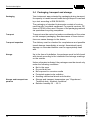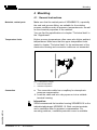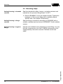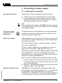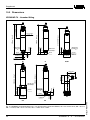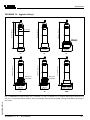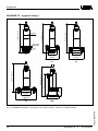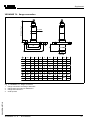
1
Operating Instructions
VEGABAR 74
4 … 20 mA/HART
p
Process pressure/
Hydrostatic
Contents
Contents
1
About this document
1.1
1.2
1.3
2
..
..
..
..
..
..
..
..
..
Configuration. . . . . . . . . . . . . . . .
Principle of operation . . . . . . . . . .
Operation . . . . . . . . . . . . . . . . . .
Packaging, transport and storage .
.
.
.
.
.
.
.
.
.
.
.
.
.
.
.
.
.
.
.
.
.
.
.
.
.
.
.
.
.
.
.
.
.. 9
. . 10
. . 10
. . 11
General instructions. . . . . . . . . . . . . . . . . . . . . 12
Mounting steps . . . . . . . . . . . . . . . . . . . . . . . . 13
Preparing the connection . . . . . . . . . . . . . . . . . 14
Connection procedure . . . . . . . . . . . . . . . . . . . 16
Wiring plan . . . . . . . . . . . . . . . . . . . . . . . . . . . 17
Setup steps without VEGADIS 12 . . . . . . . . . . . 19
Setup steps with VEGADIS 12 . . . . . . . . . . . . . 19
Setup with PACTware™
Connect the PC with VEGACONNECT 3 . . .
Connect the PC with VEGACONNECT 4 . . .
Parameter adjustment with PACTware™. . . .
Parameter adjustment with AMS™ and PDM
Saving the parameter adjustment data . . . . .
..
..
..
..
..
22
23
24
24
24
VEGABAR 74 - 4 … 20 mA/HART
28432-EN-070718
7.1
7.2
7.3
7.4
7.5
2
.
.
.
.
.
.
.
.
.
Set up
6.1
6.2
7
.
.
.
.
.
.
.
.
.
Connecting to power supply
5.1
5.2
5.3
6
6
6
6
6
7
7
7
8
8
.
.
.
.
.
.
.
.
.
Mounting
4.1
4.2
5
Authorised personnel . . . . . . . . . . . . . . .
Appropriate use. . . . . . . . . . . . . . . . . . .
Warning about misuse . . . . . . . . . . . . . .
General safety instructions . . . . . . . . . . .
Safety approval markings and safety tips
CE conformity . . . . . . . . . . . . . . . . . . . .
Fulfilling NAMUR recommendations . . . .
Safety instructions for Ex areas . . . . . . .
Environmental instructions . . . . . . . . . . .
Product description
3.1
3.2
3.3
3.4
4
5
5
5
For your safety
2.1
2.2
2.3
2.4
2.5
2.6
2.7
2.8
2.9
3
Function . . . . . . . . . . . . . . . . . . . . . . . . . . . . .
Target group . . . . . . . . . . . . . . . . . . . . . . . . . .
Symbolism used . . . . . . . . . . . . . . . . . . . . . . .
Contents
8
Maintenance and fault rectification
8.1
8.2
8.3
9
Maintenance . . . . . . . . . . . . . . . . . . . . . . . . . . 25
Fault clearance . . . . . . . . . . . . . . . . . . . . . . . . 25
Instrument repair . . . . . . . . . . . . . . . . . . . . . . . 26
Dismounting
9.1
9.2
Dismounting steps . . . . . . . . . . . . . . . . . . . . . . 27
Disposal . . . . . . . . . . . . . . . . . . . . . . . . . . . . . 27
10 Supplement
10.1
10.2
10.3
10.4
Technical data. . . . . . . .
Dimensions . . . . . . . . . .
Industrial property rights.
Trademark . . . . . . . . . .
.
.
.
.
.
.
.
.
.
.
.
.
.
.
.
.
.
.
.
.
.
.
.
.
.
.
.
.
.
.
.
.
.
.
.
.
.
.
.
.
.
.
.
.
.
.
.
.
.
.
.
.
.
.
.
.
.
.
.
.
..
..
..
..
28
35
41
41
Supplementary documentation
Information:
Depending on the ordered version, supplementary documentation belongs to the scope of delivery. You find this
documentation in chapter "Product description".
Instructions manuals for accessories and replacement
parts
Tip:
To ensure reliable setup and operation of your VEGABAR 74,
we offer accessories and replacement parts. The associated
documents are:
l
28432-EN-070718
l
l
VEGABAR 74 - 4 … 20 mA/HART
Supplementary instructions manual 32036 "Welded socket
and seals"
Operating instructions manual 32798 "Breather housing
VEGABOX 02"
Operating instructions manual 20591 "External indicating
and adjustment unit VEGADIS 12"
3
About this document
1 About this document
1.1 Function
This operating instructions manual provides all the information
you need for mounting, connection and setup as well as
important instructions for maintenance and fault rectification.
Please read this information before putting the instrument into
operation and keep this manual accessible in the immediate
vicinity of the device.
1.2 Target group
This operating instructions manual is directed to trained
personnel. The contents of this manual should be made
available to these personnel and put into practice by them.
1.3 Symbolism used
Information, tip, note
This symbol indicates helpful additional information.
Caution: If this warning is ignored, faults or malfunctions can result.
Warning: If this warning is ignored, injury to persons and/or
serious damage to the instrument can result.
Danger: If this warning is ignored, serious injury to persons
and/or destruction of the instrument can result.
Ex applications
This symbol indicates special instructions for Ex applications.
l
à
1
List
The dot set in front indicates a list with no implied sequence.
Action
This arrow indicates a single action.
Sequence
Numbers set in front indicate successive steps in a procedure.
28432-EN-070718
4
VEGABAR 74 - 4 … 20 mA/HART
For your safety
2 For your safety
2.1 Authorised personnel
All operations described in this operating instructions manual
must be carried out only by trained specialist personnel
authorised by the operator.
During work on and with the device the required personal
protection equipment must always be worn.
2.2 Appropriate use
VEGABAR 74 is a pressure transmitter for measurement of
gauge pressure, absolute pressure and vacuum.
You can find detailed information on the application range in
chapter "Product description".
Operational reliability is ensured only if the instrument is
properly used according to the specifications in the operating
instructions manual as well as possible supplementary
instructions.
Due to safety and warranty reasons, any invasive work on the
device beyond that described in the operating instructions
manual may be carried out only by personnel authorised by the
manufacturer. Arbitrary conversions or modifications are
explicitly forbidden.
2.3 Warning about misuse
Inappropriate or incorrect use of the instrument can give rise to
application-specific hazards, e.g. vessel overfill or damage to
system components through incorrect mounting or adjustment.
2.4 General safety instructions
This is a high-tech instrument requiring the strict observance of
standard regulations and guidelines. The user must take note
of the safety instructions in this operating instructions manual,
the country-specific installation standards as well as all
prevailing safety regulations and accident prevention rules.
28432-EN-070718
The instrument must only be operated in a technically flawless
and reliable condition. The operator is responsible for troublefree operation of the instrument.
VEGABAR 74 - 4 … 20 mA/HART
5
For your safety
During the entire duration of use, the user is obliged to
determine the compliance of the required occupational safety
measures with the current valid rules and regulations and also
take note of new regulations.
2.5 Safety approval markings and safety tips
The safety approval markings and safety tips on the device
must be observed.
2.6 CE conformity
VEGABAR 74 is in CE conformity with EMC (89/336/EWG),
fulfils NAMUR recommendation NE 21 and is in CE conformity
with LVD (73/23/EWG).
Conformity has been judged according to the following
standards:
l
EMC:
- Emission EN 61326: 2004 (class B)
- Susceptibility EN 61326: 2004 including supplement A
l
LVD: EN 61010-1: 2001
VEGABAR 74 is not subject to the pressure device guideline.1)
2.7 Fulfilling NAMUR recommendations
VEGABAR 74 fulfills the following NAMUR recommendations:
l
l
l
NE 21 (interference resistane and emitted interference)
NE 43 (signal level for failure information)
NE 53 (compatibility sensor and indicating/adjustment
components)
VEGA instruments are generally upward and downward
compatible:
l
l
Sensor software to DTM VEGABAR 74 HART
DTM VEGABAR 74 for adjustment software PACTware™
The parameter adjustment of the basic sensor functions is
independent of the software version. The range of available
functions depends on the respective software version of the
individual components.
1)
6
Due to the flush diaphragm, no own pressure compartment is formed.
VEGABAR 74 - 4 … 20 mA/HART
28432-EN-070718
The software version of VEGABAR 74 HART can be read out
via PACTware™.
For your safety
You can view all software histories on our website www.vega.
com. Make use of this advantage and get registered for update
information via e-mail.
2.8 Safety instructions for Ex areas
Please note the Ex-specific safety information for installation
and operation in Ex areas. These safety instructions are part of
the operating instructions manual and come with the Exapproved instruments.
2.9 Environmental instructions
Protection of the environment is one of our most important
duties. That is why we have introduced an environment
management system with the goal of continuously improving
company environmental protection. The environment management system is certified according to DIN EN ISO 14001.
Please help us fulfil this obligation by observing the environmental instructions in this manual:
l
Chapter "Packaging, transport and storage"
Chapter "Disposal"
28432-EN-070718
l
VEGABAR 74 - 4 … 20 mA/HART
7
Product description
3 Product description
3.1 Configuration
Scope of delivery
The scope of delivery encompasses:
l
l
Components
VEGABAR 74 pressure transmitter
Documentation
- this operating instructions manual
- Test certificate for pressure transmitters
- Ex-specific "Safety instructions" (with Ex-versions)
- if necessary, further certificates
VEGABAR 74 consists of the following components:
l
l
l
Process fitting with measuring cell
Housing with electronics
Connection cable (direct cable outlet)
The components are available in different versions.
1
2
3
8
1: Example of a VEGABAR 74 with process fitting G1½ A
Connection cable
Housing with electronics
Process fitting with measuring cell
VEGABAR 74 - 4 … 20 mA/HART
28432-EN-070718
Fig.
1
2
3
Product description
3.2 Principle of operation
Area of application
VEGABAR 74 is a pressure transmitter for use in the paper,
food processing and pharmaceutical industry. Thanks to the
high protection class IP 68/IP 69K it is particularly suitable for
use in humid environment. Depending on the version, it is used
for level, gauge pressure, absolute pressure or vacuum
measurements. Measured products are gases, vapours and
liquids, also with abrasive contents.
Functional principle
The sensor element is the CERTEC® measuring cell with
flush, abrasion resistant ceramic diaphragm. The hydrostatic
pressure of the medium or the process pressure causes a
capacitance change in the measuring cell via the diaphragm.
This change is converted into an appropriate output signal and
outputted as measured value.
The CERTEC® measuring cell is also equipped with a
temperature sensor. The temperature value can be processed
via the signal output.
Supply
Two-wire electronics 4 … 20 mA/HART for power supply and
measured value transmission over the same cable.
The supply voltage range can differ depending on the
instrument version.
The data for power supply are stated in chapter "Technical
data" in the "Supplement".
3.3 Operation
VEGABAR 74 4 … 20 mA/HART can be adjusted with different
adjustment media:
l
l
l
with external adjustment/indication VEGADIS 12
an adjustment software according to FDT/DTM standard,
e.g. PACTware™ and PC
with a HART handheld
28432-EN-070718
The kind of adjustment and the adjustment options depend on
the selected adjustment component. The entered parameters
are generally saved in the respecitive sensor, when adjusting
with PACTware™ and PC optionally also in the PC.
VEGABAR 74 - 4 … 20 mA/HART
9
Product description
3.4 Packaging, transport and storage
Packaging
Your instrument was protected by packaging during transport.
Its capacity to handle normal loads during transport is assured
by a test according to DIN EN 24180.
The packaging of standard instruments consists of environment-friendly, recyclable cardboard. For special versions, PE
foam or PE foil is also used. Dispose of the packaging material
via specialised recycling companies.
Transport
Transport must be carried out under consideration of the notes
on the transport packaging. Nonobservance of these instructions can cause damage to the device.
Transport inspection
The delivery must be checked for completeness and possible
transit damage immediately at receipt. Ascertained transit
damage or concealed defects must be appropriately dealt
with.
Storage
Up to the time of installation, the packages must be left closed
and stored according to the orientation and storage markings
on the outside.
Unless otherwise indicated, the packages must be stored only
under the following conditions:
l
l
l
l
l
Storage and transport temperature
l
l
Not in the open
Dry and dust free
Not exposed to corrosive media
Protected against solar radiation
Avoiding mechanical shock and vibration
Storage and transport temperature see "Supplement Technical data - Ambient conditions"
Relative humidity 20 … 85 %
28432-EN-070718
10
VEGABAR 74 - 4 … 20 mA/HART
Mounting
4 Mounting
4.1 General instructions
Materials, wetted parts
Make sure that the wetted parts of VEGABAR 74, especially
the seal and process fitting, are suitable for the existing
process conditions such as pressure, temperature etc. as well
as the chemical properties of the medium.
You can find the specifications in chapter "Technical data" in
the "Supplement".
Temperature limits
Higher process temperatures often mean also higher ambient
temperatures. Make sure that the upper temperature limits
stated in chapter "Technical data" for the environment of the
electronics housing and connection cable are not exceeded.
2
1
Fig. 2: Temperature ranges
1 Process temperature
2 Ambient temperature
Connection
l
The connection cable has a capillary for atmospheric
pressure compensation
à Lead the cable end into a dry space or into a suitable
terminal housing.
28432-EN-070718
Information:
VEGA recommends the breather housing VEGABOX 02 or the
indication/adjustment VEGADIS 12. Both contain terminals
and a ventilation filter for pressure compensation. For
mounting outdoors, a suitable protective cover is available.
VEGABAR 74 - 4 … 20 mA/HART
11
Mounting
4.2 Mounting steps
Sealing/Screwing in threaded
versions
Seal the thread with teflon, hemp or a similar resistant seal
material on the process fitting thread 1½ NPT.
à Screw VEGABAR 74 into the welded socket. Tighten the
hexagon on the process fitting with a suitable wrench.
Wrench size, see chapter "Dimensions".
Sealing/Screwing in flange
versions
Seal the flange connections according to DIN/ANSI with a
suitable, resistant seal and mount VEGABAR 74 with suitable
screws.
Sealing/Screwing in hygienic
fittings
Use the seal suitable for the respective process fitting. You can
find the components in the line of VEGA accessories in the
supplementary instructions manual "Welded socket and
seals".
28432-EN-070718
12
VEGABAR 74 - 4 … 20 mA/HART
Connecting to power supply
5 Connecting to power supply
5.1 Preparing the connection
Note safety instructions
Always keep in mind the following safety instructions:
l
l
Connect only in the complete absence of line voltage
If overvoltage surges are expected, versions with integrated overvoltage arresters should be used or external
overvoltage arresters should be installed
Tip:
We recommend the version of VEGABAR 74 with integrated
overvoltage arrester or VEGA type ÜSB62-36G.X as external
overvoltage arreaster.
Take note of safety
instructions for Ex
applications
In hazardous areas you should take note of the appropriate
regulations, conformity and type approval certificates of the
sensors and power supply units.
Select power supply
Power supply and current signal are carried on the same twowire cable. The voltage supply range can differ depending on
the instrument version.
The data for power supply are stated in chapter "Technical
data" in the "Supplement".
Provide a reliable separation of the supply circuit from the
mains circuits according to DIN VDE 0106 part 101.
VEGA power supply units VEGATRENN 149AEx, VEGASTAB
690, VEGADIS 371 as well as all VEGAMETs meet this
requirement. When using one of these instruments, protection
class III is ensured for VEGABAR 74.
Bear in mind the following factors regarding supply voltage:
l
l
28432-EN-070718
Selecting connection cable
VEGABAR 74 - 4 … 20 mA/HART
Output voltage of the power supply unit can be lower under
nominal load (with a sensor current of 20.5 mA or 22 mA in
case of fault message)
Influence of additional instruments in the circuit (see load
values in chapter "Technical data")
VEGABAR 74 is connected with standard two-wire cable
without screen. An outer cable diameter of 5 … 9 mm ensures
the seal effect of the cable gland when connecting via
VEGABOX 02 or VEGADIS 12. If electromagnetic interference
is expected which is above the test values of EN 61326 for
13
Connecting to power supply
industrial areas, screened cable should be used. For HART
multidrop operation we recommend as standard practice the
use of screened cable.
1
2
Fig. 3: Connection of VEGABAR 74
1 Direct connection
2 Connection via VEGABOX 02 or VEGADIS 12
Cable screening and grounding
If screened cable is necessary, connect the cable screen on
both ends to ground potential. In the VEGABOX 02 or
VEGADIS 12, the screen must be connected directly to the
internal ground terminal. The ground terminal on the outside of
the housing must be connected to the potential equalisation
(low impedance).
If potential equalisation currents are expected, the connection
on the processing side must be made via a ceramic capacitor
(e.g. 1 nF, 1500 V). The low frequency potential equalisation
currents are thus suppressed, but the protective effect against
high frequency interference signals remains.
14
Take note of the corresponding installation regulations for Ex
applications. In particular, make sure that no potential equalisation currents flow over the cable screen. In case of
grounding on both sides this can be achieved by the use of a
capacitor or a separate potential equalisation.
VEGABAR 74 - 4 … 20 mA/HART
28432-EN-070718
Select connection
cable for Ex applications
Connecting to power supply
5.2 Connection procedure
Direct connection
Via VEGABOX 01 or VEGADIS
12
Proceed as follows:
1
Wire the connection cable up to the connection compartment. The bending radius must be at least 25 mm.2)
2
Connect the wire ends to the screw terminals according to
the wiring plan
Proceed as follows:
1
Snap connection housing onto the carrier rail or screw it to
the mounting plate
2
Loosen the cover screws and remove the cover
3
Insert the cable through the cable entry into the connection
housing housing
4
Loosen the screws with a screwdriver
5
Insert the wire ends into the open terminals according to
the wiring plan
6
Tighten the screws with a screwdriver
7
Check the hold of the wires in the terminals by lightly
pulling on them
8
Tighten the compression nut of the cable entry. The seal
ring must completely encircle the cable
9
Connect the supply cable according to steps 3 to 8
10 Screw the housing cover back on
28432-EN-070718
The electrical connection is finished.
2)
VEGABAR 74 - 4 … 20 mA/HART
The connection cable is already preconfectioned. After shortening the cable, fasten the type plate with support again to the cable.
15
Connecting to power supply
5.3 Wiring plan
Direct connection
5
1
2
3
4
Fig.
1
2
3
4
5
4: Wire assignment, connection cable
brown (+): to power supply or to the processing system
blue (-): to power supply or to the processing system
yellow: is only required with VEGADIS 12, otherwise connect to minus or
with VEGABOX 01 to terminal 33)
Screen
Breather capillaries with filter element
3
3
2
2
1
1
4
4
5
5
6
6
Connection via VEGABOX 02
+ 1
2
Fig. 5: Terminal assignment VEGABAR 74
1 To power supply or the processing system
2 Screen4)
Wire number
VEGABAR 74 terminal
1
brown (+)
1
2
blue (-)
2
3
Yellow
2
Screen
Ground
4)
For customer-specific versions already connected with blue (-) when being
shipped.
Connect screen to ground terminal. Connect ground terminal on the outside
of the housing as prescribed. The two terminals are galvanically connected.
VEGABAR 74 - 4 … 20 mA/HART
28432-EN-070718
3)
16
Wire colour/Polarity
Connecting to power supply
Connection via VEGADIS 12
TRANSMITTER
OPERATE
ti
ZERO
SPAN
4
5
1 2 3
5 6 7 8
TRANSMITTER
NOT USED
10 11 12
+
-
4...20mA
+
VEGADIS 12
+
3
–
1
+
–
Fig.
1
2
3
4
5
6: Terminal assignment, VEGADIS 12
To power supply or the processing system
Control instrument (4 … 20 mA measurement)
Screen5)
Breather capillaries
Suspension cable
28432-EN-070718
Wire number
VEGABAR 74 - 4 … 20 mA/HART
Wire colour/Polarity
Terminal VEGADIS
12
1
brown (+)
1
2
blue (-)
2
3
Yellow
3
5)
2
Connect screen to ground terminal. Connect ground terminal on the outside
of the housing as prescribed. The two terminals are galvanically connected.
17
Set up
6 Set up
6.1 Setup steps without VEGADIS 12
After mounting and electrical connection, VEGABAR 74 is
ready for operation.
à Switch on voltage
The electronics now carries out a self-check for approx. 2
seconds. Then VEGABAR 74 delivers a current of 4 … 20 mA
according to the actual level.
6.2 Setup steps with VEGADIS 12
Adjustment volume
l
l
l
zero - measuring range begin
span - measuring range end
ti - Integration time
Adjustment system
2
TRANSMITTER
1
OPERATE
ti
ZERO
SPAN
3
1 2 3
5 6 7 8
10 11 12
+
TRANSMITTER
not used
-
4...20mA
+
VEGADIS 12
Fig.
1
2
3
l
l
l
7: Adjustment elements of VEGADIS 12
Rotary switch: choose the requested function
[+] key, change value (rising)
[-] key, change value (falling)
With the rotary switch the requested function is selected
With the [+] and [-] keys, the signal current or the
integration time are adjusted
Finally the rotary switch is set to position "OPERATE"
The set values are transmitted to the EEPROM memory and
remain there even in case of voltage loss.
Proceed as follows for adjustment with VEGADIS 12:
1
18
Open housing cover
2
Connect hand multimeter to terminals 10 and 12
3
Meas. range begin: Set rotary switch to "zero"
VEGABAR 74 - 4 … 20 mA/HART
28432-EN-070718
Adjustment steps, adjustment
Set up
4
Empty the vessel or reduce process pressure
5
Set a current of 4 mA with the [+] and [-] keys
6
Meas. range end: Set rotary switch to "span"
7
Fill the vessel or increase process pressure
8
Set a current of 20 mA with the [+] and [-] keys
9
Operation: Set rotary switch to "OPERATE"
10 Close housing cover
The adjustment data are effective, the output current 4 … 20 mA
corresponds to the actual level.
Adjustment steps, integration
time
Proceed as follows for the adjustment of the integration time
with VEGADIS 12:
1
Adjustment steps, scaling
Open housing cover
2
Set rotary switch to "ti"
3
By pushing the [-] key 10-times, make sure that the
integration time is set to 0 sec.
4
For every 1 sec. requested integration time, push the [+]
key once.
5
The integration time is the time required by the output
current signal to reach 90 % of the actual height after a
sudden level change.
6
Set rotary switch to "OPERATE"
7
Close housing cover
The display outputs the current 4 … 20 mA as bar graph and
digital value.
With 4 mA no segment of the bar graph appears, with 20 mA
all segments appear. This assignment is fix.
You can scale the digital value to any value between -9999 …
+9999 via the adjustment module.
28432-EN-070718
Proceed as follows for scaling the indication of VEGADIS 12:
VEGABAR 74 - 4 … 20 mA/HART
1
Open housing cover
2
Initial value: Set rotary switch to "zero"
3
Set the requested value, e.g. 0 with the [+] and [-] keys
4
Final value: Set the rotary switch to "span"
5
Set the requested value, e.g. 1000 with the [+] and [-] keys
6
Decimal point: Set the rotary switch to "point"
7
With the [+] and [-] keys you can adjust the requested
value, e.g. 8888 (no decimal point)
19
Set up
8
Set rotary switch to "OPERATE"
9
Close housing cover
The adjustment data are effective, the output current 4 … 20 mA
corresponds to the actual level.
28432-EN-070718
20
VEGABAR 74 - 4 … 20 mA/HART
Setup with PACTware™
7 Setup with PACTware™
7.1 Connect the PC with VEGACONNECT 3
Connecting the PC to the
signal cable
=
4
~
Power supply
3
2
VEGACONNECT 3
PACTwareTM/
1
Fig. 8: Connecting the PC to the signal cable
1 RS232 connection (with VEGACONNECT 3) or USB connection (with
VEGACONNECT 4)
2 VEGABAR 74
3 HART adapter cable
4 HART resistance 250 Ohm (optional depending on the processing)
Necessary components:
l
l
l
l
l
VEGABAR 74
PC with PACTware™ and suitable VEGA DTM
VEGACONNECT 3 or 4 with HART adapter cable (art. no.
2.25397)
HART resistance approx. 250 Ohm
Power supply unit
28432-EN-070718
Note:
With power supply units with integrated HART resistance
(internal resistance approx. 250 Ohm), an additional external
resistance is not necessary (e.g. VEGATRENN 149A, VEGADIS 371, VEGAMET 381/624/625, VEGASCAN 693). In such
cases, VEGACONNECT 3 can be connected parallel to the
4 … 20 mA cable.
VEGABAR 74 - 4 … 20 mA/HART
21
Setup with PACTware™
7.2 Connect the PC with VEGACONNECT 4
Connection via HART
4
Fig.
1
2
3
4
3
EN
OP
1
USB
TWIST
LO
CK
2
9: Connecting the PC via HART to the signal cable
VEGABAR 74
HART resistance 250 Ohm (optional depending on the processing)
Connection cable with 2 mm pins and terminals
Processing system/PLC/Voltage supply
Necessary components:
l
l
l
l
l
VEGABAR 74
PC with PACTware™ and suitable VEGA DTM
VEGACONNECT 4
HART resistance 250 Ohm (optional depending on the
processing)
Power supply unit or processing system
22
VEGABAR 74 - 4 … 20 mA/HART
28432-EN-070718
Note:
With power supply units with integrated HART resistance
(internal resistance approx. 250 Ohm), an additional external
resistance is not necessary. This applies, e.g. to the VEGA
instruments VEGATRENN 149A, VEGADIS 371, VEGAMET
381). Also usual Ex separators are most of the time equipped
with a sufficient current limitation resistor. In such cases,
VEGACONNECT 4 can be connected parallel to the 4 … 20 mA
cable.
Setup with PACTware™
7.3 Parameter adjustment with PACTware™
Further setup steps are described in the operating instructions
manual "DTM Collection/PACTware™" attached to each CD
and which can also be downloaded from our homepage. A
detailed description is available in the online help of
PACTware™ and the VEGA DTMs.
Note:
Keep in mind that for setup of VEGABAR 74, DTM-Collection
in the actual version must be used.
All currently available VEGA DTMs are provided in the DTM
Collection on CD and can be obtained from the responsible
VEGA agency for a token fee. This CD includes also the up-todate PACTware™ version. The basic version of this DTM
Collection incl. PACTware™ is also available as a free-ofcharge download from the Internet.
Go via www.vega.com and "Downloads" to the item "Software".
7.4 Parameter adjustment with AMS™ and PDM
For VEGA sensors, instrument descriptions for the adjustment
programs AMS™ and PDM are available as DD or EDD. The
instrument descriptions are already implemented in the current
versions of AMS™ and PDM. For older versions of AMS™ and
PDM, a free-of-charge download is available via Internet.
Go via www.vega.com and "Downloads" to the item "Software".
7.5 Saving the parameter adjustment data
It is recommended to document or save the parameter
adjustment data. They are hence available for multiple use or
service purposes.
28432-EN-070718
The VEGA DTM Collection and PACTware™ in the licensed,
professional version provide suitable tools for systematic
project documentation and storage.
VEGABAR 74 - 4 … 20 mA/HART
23
Maintenance and fault rectification
8 Maintenance and fault rectification
8.1 Maintenance
When used as directed in normal operation, VEGABAR 74 is
completely maintenance free.
8.2 Fault clearance
Reaction in case of failures
The operator of the system is responsible for taken suitable
measures to remove interferences.
Causes of malfunction
VEGABAR 74 offers maximum reliability. Nevertheless faults
can occur during operation. These may be caused by the
following, e.g.:
l
l
l
l
Sensor
Process
Supply
Signal processing
Fault rectification
The first measures to be taken are to check the output signals
as well as to evaluate the error messages via the indicating
and adjustment module. The procedure is described below.
Further comprehensive diagnostics can be carried out on a PC
with the software PACTware™ and the suitable DTM. In many
cases, the causes can be determined in this way and faults
can be rectified.
24 hour service hotline
However, if these measures are not successful, call the VEGA
service hotline in urgent cases under the phone no. +49 1805
858550.
The hotline is available to you 7 days a week round-the-clock.
Since we offer this service world-wide, the support is only
available in the English language. The service is free of
charge, only the standard telephone costs will be charged.
Checking the 4 … 20 mA signal
Connect a handheld multimeter in the suitable measuring
range according to the wiring plan.
? 4 … 20 mA signal not stable
l
Level fluctuations
à Adjust integration time via PACTware™
no atmospheric pressure compensation
à Check the capillaries and cut them clean
24
VEGABAR 74 - 4 … 20 mA/HART
28432-EN-070718
l
Maintenance and fault rectification
à Check the pressure compensation in the housing and
clean the filter element, if necessary
? 4 … 20 mA signal missing
l
Wrong connection to power supply
à Check connection according to chapter "Connection
steps" and if necessary, correct according to chapter
"Wiring plan"
l
No voltage supply
à Check cables for breaks; repair if necessary
l
supply voltage too low or load resistance too high
à Check, adapt if necessary
? Current signal 3.6 mA; 22 mA
l
electronics module or measuring cell defective
à Exchange instrument or return instrument for repair
In Ex applications, the regulations for the wiring of intrinsically
safe circuits must be observed.
Reaction after fault rectification
Depending on the failure reason and measures taken, the
steps described in chapter "Set up" must be carried out again,
if necessary.
8.3 Instrument repair
If a repair is necessary, please proceed as follows:
You can download a return form (23 KB) from the Internet on
our homepage www.vega.com under: "Downloads - Forms
and certificates - Repair form".
By doing this you help us carry out the repair quickly and
without having to call back for needed information.
l
l
l
28432-EN-070718
l
VEGABAR 74 - 4 … 20 mA/HART
Print and fill out one form per instrument
Clean the instrument and pack it damage-proof
Attach the completed form and, if need be, also a safety
data sheet outside on the packaging
Please ask the agency serving you for the address of your
return shipment. You can find the respective agency on our
website www.vega.com under: "Company - VEGA worldwide"
25
Dismounting
9 Dismounting
9.1 Dismounting steps
Warning:
Before dismounting, be aware of dangerous process conditions such as e.g. pressure in the vessel, high temperatures,
corrosive or toxic products etc.
Take note of chapters "Mounting" and "Connecting to power
supply" and carry out the listed steps in reverse order.
9.2 Disposal
The instrument consists of materials which can be recycled by
specialised recycling companies. We use recyclable materials
and have designed the electronics to be easily separable.
WEEE directive 2002/96/EG
This instrument is not subject to the WEEE directive 2002/96/
EG and the respective national laws (in Germany, e.g.
ElektroG). Pass the instrument directly on to a specialised
recycling company and do not use the municipal collecting
points. These may be used only for privately used products
according to the WEEE directive.
Correct disposal avoids negative effects to persons and
environment and ensures recycling of useful raw materials.
Materials: see chapter "Technical data"
If you cannot dispose of the instrument properly, please
contact us about disposal methods or return.
28432-EN-070718
26
VEGABAR 74 - 4 … 20 mA/HART
Supplement
10 Supplement
10.1 Technical data
General data
Manufacturer
VEGA Grieshaber KG, D-77761 Schiltach
Type name
VEGABAR 74
Parameter, pressure
Gauge pressure, absolute pressure, vacuum
Measuring principle
Ceramic-capacitive, dry measuring cell
Communication interface
None
Materials and weights
Material 316L corresponds to 1.4404 or 1.4435
Materials, wetted parts
- Process fitting
316L
-
Diaphragm
sapphire ceramic® (99.9 % oxide ceramic)
-
Seal
FKM (e.g. Viton), Kalrez 6375, EPDM, Chemraz 535
-
Seal process fitting thread G½ A,
G1½ A
Klingersil C-4400
Materials, non-wetted parts
- Housing
316L
-
Ground terminal
316Ti/316L
-
Connection cable
PUR, FEP, PE
-
type label support on cable
PE-HART
Weight
0.8 … 8 kg (1.8 … 17.6 lbs), depending on
process fitting
28432-EN-070718
Output variable
Output signal
4 … 20 mA/HART
Failure signal
22 mA (3.6 mA), adjustable
Max. output current
22.5 mA
Damping (63 % of the input variable)
0 … 10 s, adjustable
Step response or adjustment time
70 ms (ti: 0 s, 0 … 63 %)
Fulfilled NAMUR recommendations
NE 43
Additional output parameter - temperature
Processing is made via HART-Multidrop
VEGABAR 74 - 4 … 20 mA/HART
27
Supplement
Range
-50 … +150 °C (-58 … +302 °F)
Resolution
1 °C (1.8 °F)
Accuracy
- in the range of 0 … +100°C
(+32 … +212 °F)
±3 K
-
in the range of -50 … 0 °C
(-58 … +32 °F) and +100 … +150 °C
(+212 … +302 °F)
typ. ±4 K
Input variable
Adjustment
Zero adjustable
-20 … +95 % of the nominal measuring range
Span adjustable
3.3 … +120 % of the nominal measuring range
Recommended max. turn down
10:1
Nominal measuring ranges and overload resistance
Nominal range
Overload, max. pressure6)
Overload, min. pressure
Gauge pressure
0 … 0.1 bar/0 … 10 kPa
15 bar/1500 kPa
-0.2 bar/-20 kPa
0 … 0.2 bar/0 … 20 kPa
20 bar/2000 kPa
-0.4 bar/-40 kPa
0 … 0.4 bar/0 … 40 kPa
30 bar/3000 kPa
-0.8 bar/-80 kPa
0 … 1 bar/0 … 100 kPa
35 bar/3500 kPa
-1 bar/-100 kPa
0 … 2.5 bar/0 … 250 kPa
50 bar/5000 kPa
-1 bar/-100 kPa
0 … 5 bar/0 … 500 kPa
65 bar/6500 kPa
-1 bar/-100 kPa
0 … 10 bar/0 … 1000 kPa
90 bar/9000 kPa
-1 bar/-100 kPa
0 … 25 bar/0 … 2500 kPa
130 bar/13000 kPa
-1 bar/-100 kPa
0 … 60 bar/0 … 6000 kPa
200 bar/20000 kPa
-1 bar/-100 kPa
-1 … 0 bar/-100 … 0 kPa
35 bar/3500 kPa
-1 bar/-100 kPa
-1 … 1.5 bar/-100 … 150 kPa
50 bar/5000 kPa
-1 bar/-100 kPa
-1 … 5 bar/-100 … 500 kPa
65 bar/6500 kPa
-1 bar/-100 kPa
-1 … 10 bar/-100 … 1000 kPa
90 bar/9000 kPa
-1 bar/-100 kPa
-1 … 25 bar/-100 … 2500 kPa
130 bar/13000 kPa
-1 bar/-100 kPa
300 bar/30000 kPa
-1 bar/-100 kPa
15 bar/1500 kPa
-0.2 bar/-20 kPa
-0.1 … 0.1 bar/-10 … 10 kPa
20 bar/2000 kPa
-0.4 bar/-40 kPa
6)
28
Limited to 200 bar according to the pressure device directive.
VEGABAR 74 - 4 … 20 mA/HART
28432-EN-070718
-1 … 60 bar/-100 … 6000 kPa
-0.05 … 0.05 bar/-5 … 5 kPa
Supplement
Nominal range
Overload, max. pressure6)
Overload, min. pressure
-0.2 … 0.2 bar/-20 … 20 kPa
30 bar/3000 kPa
-0.8 bar/-80 kPa
-0.5 … 0.5 bar/-50 … 50 kPa
35 bar/3500 kPa
-1 bar/-100 kPa
Absolute pressure
0 … 0.1 bar/0 … 10 kPa
15 bar/1500 kPa
0 … 1 bar/0 … 100 kPa
35 bar/3500 kPa
0 … 2.5 bar/0 … 250 kPa
50 bar/5000 kPa
0 … 5 bar/0 … 500 kPa
65 bar/6500 kPa
0 … 10 bar/0 … 1000 kPa
90 bar/9000 kPa
0 … 25 bar/0 … 2500 kPa
130 bar/13000 kPa
0 … 60 bar/0 … 6000 kPa
200 bar/20000 kPa
Reference conditions and influencing variables (similar to DIN EN 60770-1)
Reference conditions according to DIN EN 61298-1
- Temperature
+15 … +25 °C (+59 … +77 °F)
-
Relative humidity
45 … 75 %
-
Air pressure
860 … 1060 mbar/86 … 106 kPa
(12.5 … 15.4 psi)
Determination of characteristics
Limit point adjustment according to
IEC 61298-2
Characteristics
linear
Reference installation position
upright, diaphragm points downward
Influence of the installation position
<0.2 mbar/20 Pa (0.003 psi)
Deviation determined according to the limit point method according to IEC 607707)
Applies to digital HART interface as well as to analogue current output 4 … 20 mA.
Specifications refer to the set span. Turn down (TD) = nominal measuring range/set span.
Deviation
- Turn down 1:1 up to 5:1
28432-EN-070718
-
<0.075 %
Turn down up to 10:1
<0.015 % x TD
Deviation with absolutely flush process fittings EV, FT
- Turn down 1:1 up to 5:1
<0.05 %
-
Turn down up to 10:1
<0.01 % x TD
7)
VEGABAR 74 - 4 … 20 mA/HART
Incl. non-linearity, hysteresis and non-repeatability.
29
Supplement
Deviation with absolute pressure measuring range 0.1 bar
- Turn down 1:1 up to 5:1
<0.25 % x TD
-
Turn down up to 10:1
<0.05 % x TD
Influence of the product or ambient temperature
Applies to digital HART interface as well as to analogue current output 4 … 20 mA.
Specifications refer to the set span. Turn down (TD) = nominal measuring range/set span.
Average temperature coefficient of the zero signal
In the compensated temperature range of 0 … +100 °C (+212 °F), reference temperature
20 °C (68 °F):
Average temperature coefficient of the zero signal
- Turn down 1:1
<0.05 %/10 K
-
Turn down 1:1 up to 5:1
<0.1 %/10 K
-
Turn down up to 10:1
<0.15 %/10 K
Outside the compensated temperature range:
Average temperature coefficient of the zero signal
- Turn down 1:1
typ. <0.05 %/10 K
Thermal change of the current output
Applies also to the analogue 4 … 20 mA current output and refers to the set span.
Thermal change, current output
<0.15 % at -40 … +80 °C (-40 … +176 °F)
Long-term stability (similar to DIN 16086, DINV 19259-1 and IEC 60770-1)
Applies to digital HART interface as well as to analogue current output 4 … 20 mA.
Specifications refer to the set span. Turn down (TD) = nominal measuring range/set span.
Long-term drift of the zero signal
<(0.1 % x TD)/1 year
Total deviation (similar to DIN 16086)
The total deviation (max. practical deviation) is the sum of basic accuracy and long-term
stability:
Ftotal= Fperf + Fstab
Fperf = √((FT)2 + (FKl)2)
With
- Ftotal: Total deviation
Fperf: Basic accuracy
-
Fstab: Long-term drift
30
28432-EN-070718
-
VEGABAR 74 - 4 … 20 mA/HART
Supplement
-
-
FT: Temperature coefficient (influence of medium or ambient temperature)
FKl: Deviation
Ambient conditions
Ambient, storage and transport temperature
- Connection cable PE
-
Connection cable PUR, FEP
-40 … +60 °C (-40 … +140 °F)
-40 … +85 °C (-40 … +185 °F)
Process conditions
The specifications of the pressure stage are used as an overview. The specifications on the
type plate are applicable.
Pressure stage, process fitting
- Thread 316L
-
PN 60
PN 25
Thread Alu
-
Hygienic fittings 316L
PN 10, PN 16, PN 25, PN 40
-
Flange 316L, flange with extension
316L
PN 40 or 150 lbs, 300 lbs
Product temperature depending on the measuring cell seal
- FKM (e.g. Viton)
-20 … +100 °C (-4 … +212 °F)
-
EPDM
-40 … +100 °C (-40 … +212 °F), 1 h: 140 °C/
284 °F cleaning temperature
-
Kalrez 6375 (FFKM)
-10 … +100 °C (+14 … +212 °F)
-
Chemraz 535
-30 … +100 °C (-22 … +212 °F)
Vibration resistance
mechanical vibrations with 4 g and 5 … 100 Hz8)
Shock resistance
Acceleration 100 g/6 ms9)
Electromechanical data
28432-EN-070718
Connection cable
- Configuration
four wires, one suspension cable, one breather
capillary, screen braiding, metal foil, mantle
-
Wire cross-section
0.5 mm² (AWG no. 20)
-
wire resistance
<0.036 Ohm/m (0.011 Ohm/ft)
-
Standard length
6 m (19.685 ft)
-
max. length with VEGADIS 12
200 m (656.168 ft)
8)
9)
VEGABAR 74 - 4 … 20 mA/HART
Tested according to the regulations of German Lloyd, GL directive 2.
Tested according to EN 60068-2-27.
31
Supplement
-
Min. bending radius at 25 °C/77 °F
25 mm (0.985 in)
-
Diameter
approx. 8 mm (0.315 in)
-
Colour - standard PE
Black
-
Colour - standard PUR
Blue
-
Colour - Ex-version
Blue
Voltage supply
Supply voltage
- Non-Ex instrument
-
12 … 36 V DC
EEx ia instrument
12 … 29 V DC
Permissible residual ripple
- <100 Hz
-
Uss <1 V
Uss <10 mV
100 Hz … 10 kHz
see diagram
Load
Ω
1000
710
3
500
2
1
250
4
12
Fig.
1
2
3
4
14
16
18
20
22
24
26
28
29 30
32
34
36
V
10: Voltage diagram VEGABAR 74
HART load
Voltage limit Ex instrument
Voltage limit non-Ex instrument
Voltage supply
Load in conjunction with VEGADIS 12
see diagram
28432-EN-070718
32
VEGABAR 74 - 4 … 20 mA/HART
Supplement
Ω
712,5
3
450
2
1
250
4
18
Fig.
1
2
3
4
24
29
33
36 V
11: Voltage diagram VEGABAR 74 with VEGADIS 12
HART load
Voltage limit Ex instrument
Voltage limit non-Ex instrument
Voltage supply
Integrated overvoltage protection
Nominal leakage current (8/20 µs)
10 kA
Min. response time
<25 ns
Electrical protective measures
Protection
IP 68 (25 bar)/IP 69K
Overvoltage category
III
Protection class
III
Approvals10)
ATEX ia
ATEX II 1G EEx ia IIC T6; ATEX II 2G
EEx ia IIC T6
GL, LRS, ABS, CCS, RINA, DNV
WHG
28432-EN-070718
Ship approvals
Others
10)
VEGABAR 74 - 4 … 20 mA/HART
Deviating data in Ex applications: see separate safety instructions.
33
Supplement
10.2 Dimensions
215,5 mm (8 31/64")
20 mm
(25/64")
23 mm
(29/32")
SW 27mm
(1 1/16")
252 mm (9 59/64")
ø 41,6 mm
(1 41/64")
SW 27mm
(1 1/16")
G½A
SW 46 mm
(1 13/16")
22 mm
(25/64")
111,5 mm (4 25/64")
253 mm (9 61/64")
VEGABAR 74 - threaded fitting
G½A
3 mm
(1/8")
ø 3 mm (1/8")
G1½A
NPT1½
ø 55 mm
(2 11/64")
ø 6 mm (15/64")
GI
GV
GG/GN
G1½A
69,5 mm
(2 47/64")
SW 27mm
(1 1/16")
25 mm
(63/64")
70 mm (2 3/4")
SW 46 mm
(1 13/16")
255 mm (10 3/64")
263,5 mm (10 3/8")
64,5 mm
(2 35/64")
ø 55 mm
(2 11/64")
GM
15 mm
(19/32")
½”NPT
¼”NPT
GG
GR
34
VEGABAR 74 - 4 … 20 mA/HART
28432-EN-070718
Fig. 12: VEGABAR 74 threaded fitting: GV = G½ A manometer connection EN 837, GI = G½ A inner G¼ A, GG = G1½ A,
GN = 1½ NPT, GM = G1½ A 70 mm, GR = ½ NPT inner ¼ NPT
Supplement
218,5 mm (8 39/64")
217 mm (8 35/64")
111,5 mm (4 25/64")
ø 41,6 mm
(1 41/64")
SW 46 mm
(1 13/16")
ø 64 mm
(2 33/64")
ø 78 mm
(3 5/64")
CC
CA
LA
217 mm (8 35/64")
218,5 mm (8 39/64")
ø 51 mm
(2 1/64")
218,5 mm (8 39/64")
217 mm (8 35/64")
VEGABAR 74 - hygienic fitting 1
SW 46 mm
(1 13/16")
SW 46 mm
(1 13/16")
ø 84 mm
(3 5/16")
ø 66 mm
(2 19/32" )
ø 78 mm / ø 92 mm
(3 5/64" / 3 5/8")
TA
TB
RA/RB
28432-EN-070718
Fig. 13: VEGABAR 74 hygienic fitting: CC = Tri-Clamp 1½", CA = Tri-Clamp 2", LA = hygienic fitting with compression nut
F40, TA = Tuchenhagen Varivent DN 32, TB = Tuchenhagen Varivent DN 25, RA/RB = bolting DN 40/DN 50 according to
DIN 11851
VEGABAR 74 - 4 … 20 mA/HART
35
Supplement
217 mm (8 35/64")
ø 41,6 mm
(1 41/64")
217 mm (8 35/64")
217 mm (8 35/64")
VEGABAR 74 - hygienic fitting 2
SW 75 mm
(2 61/64")
G1A
ø 60 mm
(2 23/64")
ø 66 mm
(2 19/32")
ø 95 mm
(3 47/64")
ø 105 mm
(4 9/64")
KH
AA
62 mm
(2 7/16")
169 mm (6 21/32")
222,5 mm (8 49/64")
217 mm (8 35/64")
KA
ø 70 mm
(2 3/4")
ø 150 mm
(5 29/32")
ø 86 mm
(3 25/64")
AB
SD/SE
Fig. 14: VEGABAR 74 KA/KH = cone DN 40, AA = DRD, SD/SE = Anderson 3" long/short fitting
28432-EN-070718
36
VEGABAR 74 - 4 … 20 mA/HART
Supplement
197,5 mm (7 25/32")
VEGABAR 74 - flange connection
ø 41,6 mm
(1 41/64")
f
b
d2
RL
d4
k
D
EA, FB, FE, FQ, FH, FI
d5
TV, TS
DN
PN
D
b
f
RL
d5
40
40
5 29/32"
45/64"
4 21/64" 4xø 45/64" 3 15/32"
1/8"
-
-
FB
50
40
6 1/2"
25/32"
4 59/64" 4xø 45/64" 4 1/64"
1/8"
-
-
FE
80
40
7 7/8"
15/16"
6 19/64" 8xø 45/64" 5 7/16"
1/8"
-
-
2
"
lbs
D
b
FQ
1 ½"
150
5"
11/16"
FH
2"
150
6"
3/4"
FI
3"
150
7 1/2"
3/4"
k
d2
d4
d4
f
RL
d5
3 14/16" 4xø 5/8"
2 7/8"
1/8"
-
-
4 3/4"
4xø 5/8"
3 5/8"
1/8"
-
-
6
4xø 5/8"
6
1/8"
-
-
k
d2
d4
f
RL
d5
4
1 1/2"
k
d2
3
DN
PN
D
b
TV
50
40
6 1/2"
25/32"
4 59/64" 4xø 45/64" 4 1/64"
1/8"
TS
80
40
7 7/8"
15/16"
6 19/64" 8xø 45/64" 5 7/16"
1/8"
1 1/2"
15: VEGABAR 74 - flange connection
Flange connection according to DIN 2501
Flange fitting according to ANSI B16.5
Flange with extension
Order-specific
28432-EN-070718
Fig.
1
2
3
4
1
EA
VEGABAR 74 - 4 … 20 mA/HART
37
Supplement
VEGABAR 74 - threaded fitting for paper industry
ø 41,6mm
(1 41/64")
174mm (6 27/32")
215,5mm (8 31/64")
64,5mm
(2 35/64")
SW46
M44x1,25
BA/BB
Fig. 16: VEGABAR 74 - connection for paper industry: BA/BB = M44x1.25
28432-EN-070718
38
VEGABAR 74 - 4 … 20 mA/HART
Supplement
VEGABAR 74 - extension fitting for paper industry
ø 41,6 mm
(1 41/64")
18 mm
(45/64")
ø 85 mm
(3 11/32")
2 mm
(5/64")
ø 14 mm
(35/64")
23 mm
(29/32")
134 mm (5 9/32")
175 mm (6 57/64")
64,5 mm
(2 35/64")
ø 48 mm
(1 57/64")
ø 115 mm
(4 17/32")
ø 41,6 mm
(1 41/64")
16 mm
(5/8")
154 mm (6 1/16")
FT/EV
L
ø 115 mm
(4 17/32")
ø 38 mm
(1 1/2")
28432-EN-070718
EG
Fig. 17: VEGABAR 74 - extension fitting for paper industry: EV/FT = absolutely flush for pulper (EV 2-times flattened), EG =
extension for ball valve fitting (L = order-specific)
VEGABAR 74 - 4 … 20 mA/HART
39
Supplement
10.3 Industrial property rights
VEGA product lines are global protected by industrial property rights.
Further information see http://www.vega.com.
Only in U.S.A.: Further information see patent label at the sensor housing.
VEGA Produktfamilien sind weltweit geschützt durch gewerbliche Schutzrechte.
Nähere Informationen unter http://www.vega.com.
Les lignes de produits VEGA sont globalement protégées par des droits de
propriété intellectuelle.
Pour plus d'informations, on pourra se référer au site http://www.vega.com.
VEGA lineas de productos están protegidas por los derechos en el campo de la
propiedad industrial.
Para mayor información revise la pagina web http://www.vega.com.
Линии продукции фирмы ВЕГА защищаются по всему миру правами на
интеллектуальную собственность.
Дальнейшую информацию смотрите на сайте http://www.vega.com.
VEGA系列产品在全球享有知识产权保护。
进一步信息请参见网站<http://www.vega.com>。
10.4 Trademark
All brands used as well as trade and company names are
property of their lawful proprietor/originator.
28432-EN-070718
40
VEGABAR 74 - 4 … 20 mA/HART
28432-EN-070718
Supplement
VEGABAR 74 - 4 … 20 mA/HART
41
Supplement
28432-EN-070718
42
VEGABAR 74 - 4 … 20 mA/HART
28432-EN-070718
Supplement
VEGABAR 74 - 4 … 20 mA/HART
43
VEGA Grieshaber KG
Am Hohenstein 113
77761 Schiltach
Germany
Phone +49 7836 50-0
Fax +49 7836 50-201
E-mail: [email protected]
www.vega.com
ISO 9001
All statements concerning scope of delivery, application,
practical use and operating conditions of the sensors and
processing systems correspond to the information available at the time of printing.
© VEGA Grieshaber KG, Schiltach/Germany 2007
Subject to change without prior notice
28432-EN-070718