1
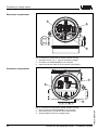
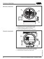
Connecting to voltage supply
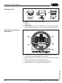
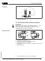
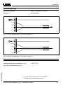
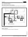
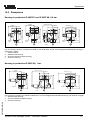
Wiring plan
1
2
1
Fig. 16: Wiring plan, double chamber housing Exd
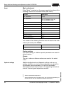
1 Power supply/Signal output
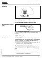
5.6 Wiring plan, version IP 66/IP 68, 1 bar
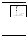
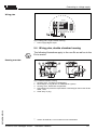
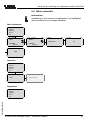
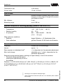
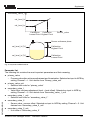
Wire assignment, connection
cable
+
1
2
Fig. 17: Wire assignment, connection cable
1 brown (+) and blue (-) to power supply or to the processing system
2 Screen
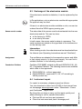
5.7 Switch-on phase
Switch-on phase
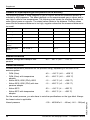
After VEGAPULS 62 is connected to voltage supply or after
voltage recurrence, the instrument carries out a self-check for
approx. 30 seconds. The following steps are carried out:
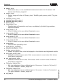
l
l
l
Internal check of the electronics
Indication of the instrument type, the firmware as well as
the sensor TAGs (sensor designation)
Status byte goes briefly to fault value
28740-EN-070130
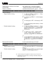
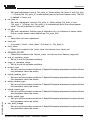
Then the current measured value will be displayed and the
corresponding digital output signal will be outputted to the
cable.3)
3)
3)
The values correspond to the actual measured level as well as to the settings already carried out, e.g. default setting.
VEGAPULS 62 standpipe version - Foundation Fieldbus
25