1
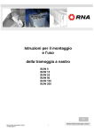
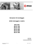
Operating instructions
Linear feeder
GL 1
GL 01
BA
Rhein-Nadel Automation GmbH
Contents
1
Technical data
Page 2
2
Safety instructions
Page 3
3
Construction and function of the linear feeder
Page 4
4
Transport and mounting
Page 4
5
Starting/Adjustment
Page 5
6
Specifications for the design of the track
Page 6
7
Maintenance
Page 7
8
Stockkeeping of spare parts and after-sales service
Page 7
9
What to do, if....?
Instructions for trouble-shooting
Page 7
Notice
All linear feeders listed in the table may only be operated in connection with a RNA control unit at a
mains voltage of 230V/50Hz. Special voltages and frequencies see separate data sheet.
1
Technical data
Linear feeder type
Dimensions L x W x H
Weight
Insulation type
Connecting cable length
Power consumption (1)
Current consumption (1)
Magnet nominal voltage (1)/Frequency
Number of magnets
Magnet type
Magnet colour
Air gap
Vibration frequency
Number of spring assemblies
Standard no. of springs
Number per spring assembly
Spring dimensions
Length (gauge for boreholes) x width
Spring size
Quality of the spring fastening screws
Tightening moment of the spring fastening
screws
Max. weight of the oscillatingunits (linear track)
depending on the mass moment of inertia and
required running speed approx.kg
Max. track length
Maximum useful weight of the linear feeder
GL 01
245 x 58 x 100
3,8
IP 54
1,4
120
0,6
200/50
1
WZAW040X00D05
black
1,0
100/6000
2
2x4
GL 1
400 x 105 x 100
8,7
IP 54
1,4
173
0,865
200/50
1
WZAW060X00D25
black
1,2
100/6000
2
2x5
in mm
45(35)x25(15)
87(67)x20
in mm
in Nm
0,5
8,8
11
1,5
8,8
25
in kg
approx. 1-2,5
approx. 2-4
in mm
in kg
400
3
600
5
in mm
in kg
in m
in VA
in A
in V/Hz
in mm
in Hz/min
(1) At special connecting values (voltage/frequency) see type plate at the magnet
Rhein - Nadel Automation GmbH
GB-C-2
Linear feeder GL 1 / 01
sure that the connected load of the linear feeder,
control unit and power supply is compatible.
Pin assignment
Notice
The linear feeder may only be operated in
perfect condition!
The linear feeder may not be operated in the
explosive or wet area.
The linear feeder may only be operated in the
configuration drive unit, control unit and oscillating
unit, as specified by the manufacturer.
2 Safety instructions
The conception and production of our linear feeders
has been carried out very carefully, in order to
guarantee trouble-free and save operation. You too
can make an important contribution to job safety.
Therefore, please read this
short operating
instruction completely, before starting the machine.
Always observe the safety instructions!
Make sure that all persons working with or at this
machine carefully read and observe the following
safety instructions!
This operating instruction is only valid for the types
indicated on the front page.
Notice
his hand points to information that gives
you useful tips for the
operation of the linear feeder.
No additional loads may act upon the linear feeder,
apart from the material to be transported, for which
the special type is designed.
Attention
It is strictly prohibited to put any safety
devices out of operation!
Demands on the user
• For all activities (operation, maintenance, repair,
etc.) the details of the operating instructions must
be observed.
• The operator has to avoid any working method
which would impair the safety of the linear feeder.
• The operator must take care that only authorized
personnel works at the linear feeder.
• The operator is obliged to inform the operator
immediately about any changed conditions at the
linear feeder that could endanger safety.
Attention
The linear feeder may only be installed,
put into operation and serviced by
expert personnel. The binding regulation
for the qualification of electricians and
personnel
instructed
in
electrical
engineering is valid, as defined in IEC 364
and DIN VDE 0105 part 1.
Attention
This warning triangle marks the safety
instructions. Non-observance of these
warnings can result in serious or fatal
injuries!
Dangers occuring at the machine
• Make sure that the protector ground of the electric
power supply is in perfect condition!
Attention:
Since the electromaget-field may have
an impact on persons arrying
pacemakers it is recommended to
keep a minimum distance of 25 cm.
• Operation of the linear feeder without trim panel is
strictly prohibited!
Proper use
The intended use of the linear feeder is the actuation
of conveying tracks. These are used for linear
transport and feeding of correctly positioned massproduced parts, as well as for the proportioned
feeding of bulk material.
Noise emission
The intended use also includes the observance of
the operating and servicing instructions.
The noise level at the place of operation depends on
the complete equipment and the material to be
sorted. The determination of the noise level
according to the EC-Regulations "Machinery" can
therefore only be carried out at the place of
operation.
Please take the technical data of your linear feeder
from the table "technical data" (see chapter 1). Make
If the noise level at the place of operation exceeds
the limit permitted, noise protection hoods may be
Rhein - Nadel Automation GmbH
GB-C-3
Linear feeder GL 1 / 01
used, which we offer as accessory parts (see
catalogue).
conduction. The vibration frequency therefore is 100
Hz.
Standards and regulations
A linear feeder is a resonant system (spring-masssystem). The result is that the adjustment made at
the plant will rarely meet your requirements. Chapter
5 describes how your linear feeder is adapted to your
requirements.
The device was built according to the following
standards and regulations:
•
•
•
•
•
•
•
•
3
EC- Directive Machinery 98/37/EC
EC- Low voltage directive 73/23/EC
EMC- Directive 89/336/EC
Applied harmonized Standards
EN 60204, T.1
EN 292, T.1 and T.2
Applied national technical standards
VGB 4
VGB 10
Rheinnadel- Conditions for purchasing
VDE- Standards
VDMA- Conditions of delivery
Controlling of the linear feeder takes place by a low
loss electronic control unit type ESG 90. The control
unit of the linear feeder is separately delivered. At its
front panel it is provided with a 7-pole plug-in
connection, by which it is connected to the linear
feeder.
The pin assignment of the socket is shown in the
table "technical data" (chapter 1).
Notice
Detailed information on the complete
range of control units may please
be taken from the operating
instructions for control units
Construction and function of the
linear feeder
All control units have got two main operating
elements:
Linear feeders are used for the actuation of sorting
machines. The actuation takes place by
electromagnets. The following schematic diagram
shows the function of a linear feeder:
• By the main switch the linear feeder is switched
on or off.
• By the turning knob the conveying caacity of the
sorting unit is set.
4
Transport and mounting
Transport
Notice
Take care that the linear feeder cannot
dash against other things during
transport
A
B
C
D
E
F
G
The weight of the linear feeder is taken from the table
„technical data“ (chapter 1.)
Conveying track and oscillating weight
Material to be conveyed
Spring assembly
Drive magnet
Armature
Counter-mass
Vibration buffers
The linear feeder is a device of the familiy of vibratory
bowl feeders. It is, however, equipped with a linear
conveyor. Electromagnetic vibrations are converted
into mechanical vibrations and are used for
conveying material B. When the magnet D, which is
fixedly connected with the counter-mass F, is
supplied with current, it generates a power that,
dependent on the vibration frequency of the mains
supply, attracts and releases armature E. Within a
period of the 50 Hz of the A.C. network the magnet
achieves its maximum power of attraction twice, as
this is independent of the direction of the current
Rhein - Nadel Automation GmbH
Mounting
The linear feeder should be mounted on a stable
substructure (available as accessory part) at the
place where it is used. The substructure must be
dimensioned in a way that no vibrations of the linear
feeder can be carried away.
Linear feeder are fastened to the vibration buffers
from below (part G in the general drawing chap. 3).
The following table give you a summary of the bore
date of the various types:
Linear
feeder type
GL 01
GL 1
Length in
mm
Width in
mm
152
285
40
70
Vibration
buffer
thread
M4
M6
Table bore data
GB-C-4
Linear feeder GL 1 / 01
Make sure that the linear feeder cannot come into
contact with other devices during operation.
Further details on the control unit (bore plan, etc.) are
please taken from the operating instructions of the
control unit separately delivered.
5.
Starting
Preparations
Notice
Ensure that the frame ( stand, base,
frame etc.) is connected with the
ground wire. (PE) If necessary,
predection earthing on spot should be
provided.
Check, whether
• the linear feeder stands in an isolated position
and does not come in contact with a solid body
• the linear track is fixedly screwed down and
adjusted
• the connecting cable of the linear feeder is
plugged in at the control unit.
Attention
The electric connection of the linear
feeder may only be made by trained
personnel
(electricians)!
In
case
modifications are made at the electric
connection, it is absolutely necessary to
observe the operating instructions
"control units".
• The available supply voltage (frequency, voltage,
output) is in accordance with the connection data
of the control unit (see type plate at the control
unit).
Plug in the mains cable of the control unit and switch
on the control unit by the mains switch.
Notice
At linear feeders which are delivered as a
completely adjusted system, the optimal
conveying capacity is already set in the
factory. It is marked on the scale of the
turning knob with a red arrow. In this
case set the turning knob to the marking
The optimal operative range of the linear feeder is at
a controller position of 80% at the control unit. In
case of higher deviations (≥±15%) a new adjustment
must be made.
Adjustment of the running behaviour
Notice
At first a rough adjustment of the
conveying speed (adjustment of the
natural frequency must be made. After
Rhein - Nadel Automation GmbH
that the adjustment of the running
behaviour. Finally you adjust the
conveying speed (natural frequency).
In order to convey the material with its highest
(maximum) conveying speed, it must optimally rest
on (in) the track, which means that the vertical
amplitude should be zero, if possible. At long tracks
the vertical amplitude can be too high, owing to the
deflection of the track. The material to be conveyed
then makes little jumps on the track and cannot be
transported at all or only with low speed.
In exceptional cases it may become necessary to
compensate the fluttering of the track at the ends by
modifying the counter-weight. In case the workpieces
make little jumps at the discharge side or in case the
material to be conveyed runs backward, the counterweight must be increased (stepwise by approx. 50 g).
In case the workpieces make little jumps at the
feeding side (magnet side) or if their is no conveying
movement at the discharge side, the counter-weight
must be decreased.
Adjustment of the natural frequency
In case the linear feeders are delivered without track,
they has been adjusted in the plant to average
weights of the oscillating elements. In order to
guarantee an optimal conveying behaviour, the linear
feeder must be adjusted to the definite operating
conditions.
The adjustment is made by adding or removing leaf
springs and washers.
First check, whether the right control unit (frequency,
voltage, power supply, (see table "technical data" in
chapter 1) has been connected.
Carry out the following steps:
• Screw off the side panels. Tighten all spring
fastening screws and track fastening screws.
Please take the tightening moments of the spring
fastening screws from the table technical data
(chapter 1).
• Check, whether the magnet corresponds to the
specifications in the "technical data" (voltage,
frequency).
• Measure the magnet-air gap. In case it differs
from the specifications in the "technical data",
adjust it correctly.
• Fill the tracks with material to be conveyed and
turn the turning knob of the control unit to 90 % of
the conveying capacity.
• Loosen a fastening screw at one of the spring
assemblies
• (approx. 1/4-1/2 rotation).
While the spring fastening screw is loosened, you
can see a change in the conveying speed.
The following graphic chart shows the resonance
curve of a linear feeder:
GB-C-5
Linear feeder GL 1 / 01
magnetic gap the magnet may not dash
against the armature when switching on
the device.
The aim of the adjustment is:
If the required conveying speed is achieved at a
controller position of 80 %, the conveying speed
must always decrease when the spring fastening
screw is loosened.
A
B
C
D
Notice
Take care that the number of springs per
spring assembly does not differ by more
than 2-3 springs.
Conveying speed
Resonant frequency of the system
Resonance curve (not true to scale)
Spring power
Notice
The resonant frequency of the linear
feeder may not correspond to the mains
frequency
In case the conveying capacity decreases after
loosening the spring fastening screw, proceed as
described under point 5.1.
In case, however, the conveying capacity, increases,
proceed as described under point 5.2.
Notice
The adjustment is, however, more easy
with an electronic frequency converter,
which you can buy from our range of
accessory parts.
The linear feeder should be adjusted that the
required conveying capacity is achieved at a
controller position of approx. 80% at the control unit.
5.1
The conveying speed decreases?
Mount additional springs (with distance plates). Start
with one additional spring (with washer) at one spring
assembly. In case the conveying speed still
decreases, although an additional fastening
screw is loosened, install one additional spring in
each individual spring assembly (one after the other).
5.2
The conveying speed increases?
Remove the springs. First remove one spring (with
washer) from a spring assembly. In case the
conveying speed still increases, although an
additional fastening screw is loosened, remove one
spring from each individual spring assembly (one
after the other).
After removing and mounting of the leaf springs the
linear feeder must be readjusted.
Adjustment of the linear feeder type GL 01:
Tighten the spring fastening screws with the
specified tightening torque (see "technical data"
chapter 1). Control and keep to the mounting
dimension (oscillator height) of 85 mm at all four
edges of the linear feeder. Before starting the side
plates must be mounted.
Adjustment of the linear feeder type GL 1:
For the adjustment of the oscillator in parallel to the
counter-mass four leaf springs are included in the
delivery. These leaf springs must be inserted
between the spring assemblies and the distance
cams (one each above and below). After that the
spring fastening screws must be tightened with the
specified tightening torque (see "technical data"
chapter 1). Before starting the distance springs must
be removed and the side plates must be mounted.
6
Specifications for the design of the
track
The projection of the track in longitudinal direction
towards the oscillator should be at a ratio of 1/3
feeding side to 2/3 discharge side.
The tracks must be of solid construction. upright
beams with a high moment of resistance are to be
preferred (U-beams, rectangular tubes, etc.).
Notice
The side plates must always be mounted
for test runs
Especially tracks for thin material as eg. stamped
metal parts, etc. should be manufactured with the
greatest possible clearance between material to be
conveyed and cover. Here it must, however, be
guaranteed that the material to be conveyed does
not run one piece on top of the other or becomes
wedged together.
Notice
At a turning knob position of 100 % at the
control unit and correctly adjusted
The track should be located in the middle of the
oscillator. By no means it may be installed in a way
that one side projects over the oscillator.
Rhein - Nadel Automation GmbH
GB-C-6
Linear feeder GL 1 / 01
8.
7
Maintenance
The linear feeders are generally maintenance-free.
They should, however, be thoroughly cleaned when
they are considerably dirty or after fluids have been
spilled over them.
• For that first unplug the mains plug.
• Remove the side plates.
• Clean the inside of the linear feeder, especially
the magnetic gap.
• After mounting the side plates and plugging in the
mains plug, the linear feeder is ready for
operation again.
9
Stockkeeping of spare parts and
after-sales service.
The range of the spare parts available may be taken
from the separate spare parts list.
In order to guarantee quick and faultless handling of
the order, please always state the type of equipment
(see type plate), number of pieces needed, spare
part name and spare part number.
You will find a list of our service addresses on the
back page of the cover
What is to do, if...
Instructions for trouble-shooting
Attention
The control unit or the connecting terminal box may only be opened by an electrician. Before opening
the a.m. devices, the mains plug must be unplugged!
Trouble
Linear feeder does not
start when being switchen
on
Possible cause
Mains switch off
Remedy
Switch on the mains switch
Mains plug of the control unit is not plugged in
Plug in the mains plug.
Connecting cable between linear feeder and control
unit is not plugged in
Plug in the 7-pole plug at the control unit
Replace the fuse
Linear feeder vibrates
slightly
Fuse in the control unit defective
Turning knob at the control unit is set to 0%
Wrong vibration frequency
Attention:
in case a linear feeder for 6000 vibrations/minute is
operated with a 7-pole plug without bridge, the
control unit and the magnet is in danger!
After a longer operating
Fastening screws of the linear track have worked
time the linear feeder does loose
no longer come up to the
conveying capacity
Screws at one or two spring assemblies have
required
worked loose
Set the controller to 80%.
Check, whether the code in the plug of the
linear feeder is correct (see type plate and
"technical data" (chap. 1)
Retighten the screws.
Tighten the screws (tightening torques see
"technical data" (chapt. 1)
Replace the broken springs
Magnetic gap misadjusted
Readjust the oscillator
(see chapt. 5)
Springs are broken
Linear feeder produces
loud noise
Oscillator has displaced itself towards the countermass
Fastening screws of the side plates have worked
loose
Foreign bodies in the magnetic gap
Linear feeder cannot be
adjusted to a constant
conveying speed
The spring constant of the oscillating system has
changed. The linear feeder works close to the
resonance point
Rhein - Nadel Automation GmbH
GB-C-7
Retighten the screws
Switch off the linear feeder and remove the
foreign bodies, after that check the magnetic
gap adjustment
Readjust the linear feeder. Springs must be
removed. See chapt. 5, adjustments
Linear feeder GL 1 / 01
Rhein-Nadel Automation GmbH
Reichsweg 19/42 y D - 52068 Aachen
Tel (+49) 0241/5109-159 y Fax +(49) 0241/5109-219
Internet www.rna.de y Email [email protected]
Rhein-Nadel Automation GmbH
Zweigbetrieb Lüdenscheid
Nottebohmstraße 57 y D - 58511 Lüdenscheid
Tel (+49) 02351/41744 y Fax (+49) 02351/45582
Email [email protected]
Rhein-Nadel Automation GmbH
Zweigbetrieb Ergolding
Ahornstraße 122 y D - 84030 Ergolding
Tel (+49) 0871/72812 y Fax (+49) 0871/77131
Email [email protected]
HSH Handling Systems AG
Wangenstr. 96 y CH - 3360 Herzogenbuchsee
Tel +(41) 062/95610-00 y Fax (+41) 062/95610-10
Internet www.rna.de y Email [email protected]
RNA AUTOMATION LTD
Hayward Industrial Park
Tameside Drive, Castle Bromwich
GB - Birmingham, B 35 7 AG
Tel (+44) 0121/749-2566 y Fax (+44) 0121/749-6217
Internet www.rna-uk.com y Email [email protected]
Vibrant S.A.
Pol. Ind. Famades C/Energia Parc 27
E - 08940 Cornella Llobregat (Barcelona)
Tel (+34) 093/377-7300 y Fax (+34) 093/377-6752
Internet www.vibrant-rna.com y Email [email protected]
RNA Automated Systems Inc.
1349 Sandhill Drive Unit 101
Ancaster, Ontario
Canada, L9G 4V5
Tel (+1) 905/3049950 y Fax (+1) 905/3049951
Mobil (+1) 905/9756562
Email [email protected]
www.rna-can.com
VT-BA-GL-GB-00
Stand: 05.06.06
8
Linear feeder GL 1 / 01