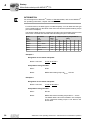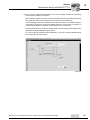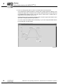
1
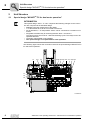
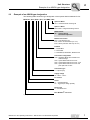
Drive Technology \ Drive Automation \ System Integration \ Services Addendum to the Operating Instructions MOVIFIT® FC Special Design for Dual-Motor Operation Edition 04/2011 17077214 / EN SEW-EURODRIVE—Driving the world Content Content 1 2 General information ............................................................................................ 4 1.1 Structure of the safety notes ....................................................................... 4 1.2 Rights to claim under limited warranty ........................................................ 5 1.3 Exclusion of liability..................................................................................... 5 1.4 Other applicable documentation ................................................................. 5 Unit Structure ...................................................................................................... 6 2.1 3 4 Special design "MOVIFIT® FC for dual-motor operation" ........................... 6 2.2 Example of an ABOX type designation ....................................................... 7 2.3 Accessories................................................................................................. 8 Electrical Installation .......................................................................................... 9 3.1 Terminal assignment................................................................................... 9 3.2 Replacing switching relays........................................................................ 13 Startup................................................................................................................ 14 4.1 Startup procedure for MOVIFIT® FC......................................................... 14 4.2 Preparations.............................................................................................. 15 4.3 Motor/brake startup with MOVIFIT® FC .................................................... 18 4.4 Switchover between drive 1 and drive 2 ................................................... 31 Addendum to the Operating Instructions – MOVIFIT® FC for Dual-Motor Operation 3 General Information Structure of the safety notes 1 1 General Information 1.1 Structure of the safety notes 1.1.1 Meaning of the signal words MOVIFIT¬Æ FC for Dual-Motor Operation The following table shows the grading and meaning of the signal words for safety notes, notes on potential risks of damage to property, and other notes. Signal word 1.1.2 Meaning Consequences if disregarded DANGER Imminent danger Severe or fatal injuries WARNING Possible dangerous situation Severe or fatal injuries CAUTION Possible dangerous situation Minor injuries NOTICE Possible damage to property Damage to the drive system or its environment INFORMATION Useful information or tip: Simplifies the handling of the drive system. Structure of the section-related safety notes Section safety notes do not apply to a specific action, but to several actions pertaining to one subject. The used symbols indicate either a general or a specific hazard. This is the formal structure of a section safety note: SIGNAL WORD Type and source of danger. Possible consequence(s) if disregarded. • 1.1.3 Measure(s) to prevent the danger. Structure of the embedded safety notes Embedded safety notes are directly integrated in the instructions just before the description of the dangerous action. This is the formal structure of an embedded safety note: • SIGNAL WORD Nature and source of hazard. Possible consequence(s) if disregarded. – Measure(s) to prevent the danger. 4 Addendum to the Operating Instructions – MOVIFIT® FC for Dual-Motor Operation General Information Rights to claim under limited warranty 1.2 1 Rights to claim under limited warranty A requirement of fault-free operation and fulfillment of any rights to claim under limited warranty is that you adhere to the information in the operating instructions. Therefore, read the operating instructions before you start working with the unit Make sure that the operating instructions are legible and available to persons responsible for the plant and its operation, as well as to persons who work independently on the unit. 1.3 Exclusion of liability You must comply with the information contained in these operating instructions to ensure safe operation of MOVIFIT®-FC and to achieve the specified product and performance features. SEW-EURODRIVE assumes no liability for injury to persons or damage to equipment or property resulting from non-observance of these operating instructions. In such cases, any liability for defects is excluded. 1.4 Other applicable documentation • This additional information does not replace the detailed operating instructions and manual. • Installation and startup only by trained personnel observing the relevant accident prevention regulations and the following publications: • "MOVIFIT® FC" operating instructions and • "MOVIFIT® – Functional Safety" manual and • "MOVIFIT® Function Level Classic ..." manual or • "MOVIFIT® Function Level Technology ..." manual Addendum to the Operating Instructions – MOVIFIT® FC for Dual-Motor Operation 5 Unit Structure Special design "MOVIFIT® FC for dual-motor operation" 2 2 Unit Structure 2.1 Special design "MOVIFIT® FC for dual-motor operation" INFORMATION This special design ""MTA...-S..-30." comprises the following changes on the connection box compared to the standard design: • • • • • • Modified connection assignment of the ABOX. 1 TH thermostat each can be connected to all motors. As an alternative, 1 TF temperature sensor can be connected to a maximum of 2 motors. Integrated K1/K2/K3 relay for switching between drive 1 and drive 2. The relays have a service life of 1 000 000 switching cycles. The relays have to be replaced after that. The binary output DB00 is not available. This special design is not permitted for hoist operation. The following figure shows the connection board of the special design "MOVIFIT® FC for dual-motor operation": X1 X10 X9 X8 X81 X20 X29 X45 X25 X30 X31 X35 X50 K1 K3 K2 1737858315 6 Addendum to the Operating Instructions – MOVIFIT® FC for Dual-Motor Operation Unit Structure Example of an ABOX type designation 2.2 2 Example of an ABOX type designation The following table shows the type designation of the special ABOX of MOVIFIT® FC: MTA11A - 503 - S533 - D01 - 30 / BW2 / M11 Option 2 ABOX M11 = Stainless steel mounting rail Option 1 ABOX BW1 / BW2 = Integrated braking resistor ABOX variant 30 = Special design Dual-motor operation Maintenance switch D01 = Load disconnector M11 = Motor circuit breaker up to 4 A1) M12 = Motor protection switch up to 9 A1) Fieldbus 1 = PROFIBUS 2 = DeviceNet 3 = EtherNet/IP, PROFINET, Modbus/TCP Connection configuration S02 = Standard ABOX with terminals and cable bushings S42 = Hybrid ABOX with M12 for I/Os S52 = Hybrid ABOX with M12 for I/Os + bus S62 = Hybrid ABOX with M12 for I/Os and push-pull RJ45 for bus Connection type 3 = 3-phase (AC) Supply voltage 50 = 380 V – 500 V A = version Series 11 = Standard (IP65) 12 = Hygienicplus design (IP69K) Device type A = Connection box MT = MOVIFIT® unit series 1) Only available in connection with UL Addendum to the Operating Instructions – MOVIFIT® FC for Dual-Motor Operation 7 Unit Structure Accessories 2 2.3 Accessories The following accessories are required for replacing faulty relays. The relays can also be replaced during maintenance to increase system availability. The accessories are available from SEW-EURODRIVE. Type Figure Content Switching relay including support bracket Part number 3 pc 1 821 747 8 30 pc 1 821 748 6 + 8 Addendum to the Operating Instructions – MOVIFIT® FC for Dual-Motor Operation Electrical Installation Terminal assignment 3 3 Electrical Installation INFORMATION • • • 3.1 The following chapter describes the modified connection assignment of the ABOX. For the terminal assignment of all terminals that are not described here, refer to the "MOVIFIT® FC" operating instructions. Observe the "MOVIFIT® FC" operating instructions, in particular the safety and warning notes. Terminal assignment WARNING Electric shock due to dangerous voltages present in the ABOX. The maintenance switch only disconnects the integrated frequency inverter from the power supply. Voltage is still present on the terminals of the MOVIFIT® unit. Severe or fatal injuries. • 3.1.1 Switch off the power to MOVIFIT® using a suitable external disconnecting device, and wait at least 1 minute before opening the wiring space. X1: Line terminals (power bus) X8 X1 1 2 3 4 11 12 13 14 1 2 X10 1 2 3 1 K1 K3 K2 2 4 X81 X9 1 234 5 5 3 X8 6 X9 6 4 X30 X29 1 2345 678 1 2 3 5 6 11 12 13 15 16 7 1 2 3 4 5 S2 1 23 S1 1 2 3 4 5 6 7 8 1 2 3 X31 S3 11 12 13 14 15 11 12 13 14 15 16 17 18 21 22 23 24 25 21 22 23 24 25 26 27 28 1 2 3 4 5 11 12 13 14 15 31 32 33 34 35 31 32 33 34 35 36 37 38 7 X20 X45 X35 X25 X50 1739094539 Line terminal (power bus) No. X1 Name Function 1 PE Line connection PE (IN) 2 L1 Line connection phase L1 (IN) 3 L2 Line connection phase L2 (IN) 4 L3 Line connection phase L3 (IN) 11 PE Line connection PE (OUT) 12 L1 Line connection phase L1 (OUT) 13 L2 Line connection phase L2 (OUT) 14 L3 Line connection phase L3 (OUT) Addendum to the Operating Instructions – MOVIFIT® FC for Dual-Motor Operation 9 Electrical Installation Terminal assignment 3 3.1.2 X20: 24 V supply terminal (24 V power bus) X8 X1 1 2 3 4 11 12 1 13 1 14 1 2 X10 1 2 3 1 4 2 X9 K1 K3 K2 5 5 1 234 3 X8 6 X9 6 4 X30 X29 X81 1 2345 678 1 2 3 5 6 11 12 13 15 16 1 2 3 4 5 1 2 3 4 5 6 7 8 1 2 3 X31 S3 11 12 13 14 15 11 12 13 14 15 16 17 18 21 22 23 24 25 21 22 23 24 25 26 27 28 7 S2 1 23 S1 1 2 3 4 5 11 12 13 14 15 31 32 33 34 35 31 32 33 34 35 36 37 38 7 X20 X45 X35 X25 X50 1741520651 24 V supply terminal (24 V power bus) No. X20 10 Name Function 1 FE Functional earth (IN) 2 +24V_C +24 V continuous voltage supply (IN) 3 0V24_C 0V24 reference potential - continuous voltage (IN) 5 +24V_S +24 V supply – switched (IN) 6 0V24_S 0V24 reference potential – switched (IN) 11 FE Functional earth (OUT) 12 +24V_C +24 V continuous voltage supply (OUT) 13 0V24_C 0V24 reference potential - continuous voltage (OUT) 15 +24V_S +24 V supply – switched (OUT) 16 0V24_S 0V24 reference potential – switched (OUT) Addendum to the Operating Instructions – MOVIFIT® FC for Dual-Motor Operation Electrical Installation Terminal assignment 3.1.3 3 X8, X81, X9 and X91: Connection terminals for motor and braking resistor X8 X1 1 2 3 4 11 12 1 13 1 14 1 2 X10 1 2 4 X9 1 234 3 1 2 K1 K3 K2 5 5 3 X8 6 X9 6 4 X30 X29 X81 1 2345 678 1 2 3 5 6 11 12 13 15 16 7 1 2 3 4 5 S2 1 23 S1 1 2 3 4 5 6 7 8 1 2 3 X31 S3 11 12 13 14 15 11 12 13 14 15 16 17 18 21 22 23 24 25 21 22 23 24 25 26 27 28 1 2 3 4 5 11 12 13 14 15 31 32 33 34 35 31 32 33 34 35 36 37 38 7 X20 X45 X35 X25 X50 1741527563 Motor connection terminal (connection via hybrid cable) No. X8 X9 X81 X10 Name Function 1 PE Motor 1 PE connection 2 U Output motor 1 phase U 3 V Output motor 1 phase V 4 W Output motor 1 phase W 5 15 Connection for SEW brake motor 1 terminal 15 (blue) 6 14 Connection for SEW brake motor 1 terminal 14 (white) 7 13 Connection for SEW brake motor 1 terminal 13 (red) 1 PE Motor 2 PE connection 2 U Output motor 2 phase U 3 V Output motor 2 phase V 4 W Output motor 2 phase W 5 15 Connection for SEW brake motor 2 terminal 15 (blue) 6 14 Connection for SEW brake motor 2 terminal 14 (white) 7 13 Connection for SEW brake motor 2 terminal 13 (red) 1 TH+ Connection for temperature sensor TH/TF (+) motor 1 2 TH- Connection for temperature sensor TH/TF (-) motor 1 3 TH+ Connection for temperature sensor TH/TF (+) motor 2 4 TH- Connection for temperature sensor TH/TF (-) motor 2 1 -R Braking resistor connection -R 2 +R Braking resistor connection +R Addendum to the Operating Instructions – MOVIFIT® FC for Dual-Motor Operation 11 Electrical Installation Terminal assignment 3 3.1.4 X29: 24V distributor terminal WARNING When you use terminals X29/5 and X29/6 for safe disconnection, you must observe the publication "MOVIFIT® – Functional Safety". Severe or fatal injuries. • Observe the permissible wiring diagrams and safety conditions in the SEW publication "MOVIFIT® – Functional Safety". X8 X1 1 2 3 4 11 12 1 13 1 14 1 2 3 X10 1 2 K1 K3 K2 5 5 4 X81 X9 1 234 X8 6 X9 6 1 2 3 4 5 S2 1 23 S1 1 2345 678 1 2 3 5 6 11 12 13 15 16 7 X30 X29 1 2 3 4 5 6 7 8 1 2 3 X31 S3 11 12 13 14 15 11 12 13 14 15 16 17 18 21 22 23 24 25 21 22 23 24 25 26 27 28 1 2 3 4 5 11 12 13 14 15 31 32 33 34 35 31 32 33 34 35 36 37 38 7 X20 X45 X35 X25 X50 1741533579 24V distributor terminal (for distributing the supply voltage(s) to the integrated inverter and the option card) No. Name Function X29 1 +24V_C +24 V supply for binary inputs – continuous voltage (jumpered with X20/2) 2 0V24_C 0V24 reference potential for binary inputs - continuous voltage (jumpered with X20/3) 3 +24V_S +24 V supply for binary outputs – switched (jumpered with X20/5) 4 0V24_S 0V24 reference potential for binary outputs – switched (jumpered with X20/6) 5 +24V_P +24 V supply for integrated frequency inverter (IN) 6 0V24_P 0V24 reference potential for integrated frequency inverter (IN) 7 +24V_O +24V supply for option card, supply 8 0V24_O 0V24 reference potential for the option card, supply 12 Addendum to the Operating Instructions – MOVIFIT® FC for Dual-Motor Operation Electrical Installation Replacing switching relays 3.2 3 Replacing switching relays WARNING Disconnect the units from power before installing/removing the relay. Dangerous voltages may still be present for up to one minute after disconnection from the power supply. Severe or fatal injuries from electric shock. • • Disconnect the MOVIFIT® from the mains using an appropriate external disconnecting device and secure it against unintentional reconnection to the voltage supply. Then wait at least for 1 minute. You can replace the K1, K2 or K3 switching relays as follows: 1. Remove the support brackets of the relay. 2. Carefully remove the relay in upward direction. Important: Make sure you do not tilt the relay to prevent the socket and its pins from being damaged. 90° 1. 2. 3. 1741934859 3. Replace the faulty relay by the new one and install the parts in reverse order. Make sure you do not damage the new relay when inserting it. INFORMATION SEW-EURODRIVE recommends to replace all 3 relays to increase system availability. Addendum to the Operating Instructions – MOVIFIT® FC for Dual-Motor Operation 13 I 4 Startup Startup procedure for MOVIFIT® FC 0 4 Startup 4.1 Startup procedure for MOVIFIT® FC The following chapter describes how to start up the special design MOVIFIT® FC motor. Observe the additional documents listed in the following table: WARNING If you use applications with safe disconnection, you must additionally observe the SEW publication "MOVIFIT® – Functional Safety". Severe or fatal injuries. • Observe the additional startup notes and safety conditions in the SEW publication "MOVIFIT® – Functional Safety". [1] Motor startup → For information, refer to: • "DR.71-225, 315 AC Motors" operating instructions, or • "DR/DV/DT/DTE/DVE AC Motors, CT/CV Asynchronous Servomotors" operating instructions [2] Starting up MOVIFIT® FC → For information, refer to: • "MOVIFIT® FC" operating instructions [3] Parameter setting1) Programming with MOVITOOLS® MotionStudio → For information, refer to: • "MOVIFIT Function Level Classic..." manual 2) • "MOVIFIT Function Level Technology..." manual. 2) • "MOVI-PLC® Programming in the PLC Editor" manual • "MPLCMotion_MC07 and MPLCMotion_MM Libraries for MOVI-PLC®" manual Fieldbus configuration → For information, refer to: • "MOVIFIT® FC" operating instructions, chapter: "Starting up MOVIFIT® on the fieldbus" • "MOVIFIT Function Level Classic..." manual 2) • "MOVIFIT Function Level Technology..." manual. 2) [4] 1) Parameters can only be set in "Expert mode". 2) The "MOVIFIT® Function Level Classic" and "MOVIFIT® Function Level Technology" manuals are available in several fieldbusspecific variants. 14 Addendum to the Operating Instructions – MOVIFIT® FC for Dual-Motor Operation Startup Preparations I 4 0 4.2 Preparations 4.2.1 MOVITOOLS® MotionStudio The "MOVITOOLS® MotionStudio" software package is the SEW engineering tool you can use to access all SEW drive units. With simple applications, you can use MOVITOOLS® MotionStudio to perform diagnostics for the MOVIFIT® unit series. For more demanding applications, you can use the wizards available in MOVITOOLS® MotionStudio to startup, configure and program MOVIFIT® units. MOVITOOLS® MotionStudio can communicate with the drive units using different communication links and fieldbus systems. The most simple application for connecting a PC/laptop and a MOVIFIT® unit via the diagnostic interface (serial RS485) (point-to-point connection) is described in the following chapter: 4.2.2 Preparations on MOVIFIT® 1. Always follow the safety and warning instructions in the relevant operating instructions when working on MOVIFIT® units. 2. Install the latest software version of MOVITOOLS® MotionStudio (version 5.6.0 or higher) on your PC/laptop. 3. Set DIP switch S10/1 to "ON" (activating "Expert mode") S10 ON 1 2 3 4 5 6 837925643 Addendum to the Operating Instructions – MOVIFIT® FC for Dual-Motor Operation 15 I 4 Startup Preparations 0 4.2.3 Connecting the PC The following figure shows the connection of a a PC/laptop to the diagnostic interface X50 of MOVIFIT®: MOVIFIT ® X50 USB11A RS-232 RS485 RJ10 UWS21B USB RS485 RJ10 812444555 The diagnostic interface can be connected to a PC using one of the following options: 16 • USB11A with USB interface, part number 0 824 831 1 • UWS21B with serial interface RS-232, part number 1 820 456 2 Addendum to the Operating Instructions – MOVIFIT® FC for Dual-Motor Operation Startup Preparations I 4 0 4.2.4 Including MOVIFIT® in MOVITOOLS® MotionStudio Starting the software and creating the project Proceed as follows to start MOVITOOLS® MotionStudio and create a project: 1. Start the MOVITOOLS® MotionStudio from the Windows start menu via: [Start]/[Programs]/[SEW]/[MOVITOOLS-MotionStudio]/[MOVITOOLS-MotionStudio] 2. Create a project with a name and directory. Establishing communication and scanning the network Proceed as follows to establish a communication with MOVITOOLS® MotionStudio and scan your network: 1. Set up a communication channel to communicate with your units. For detailed information on how to configure a communication channel, see the chapter about the relevant communication type. 2. Scan your network (unit scan). Press the [Start network scan] button [1] in the toolbar. [1] 3. Select the unit you want to configure. 4. Right-click to open the context menu. As a result you will see a number of unit-specific tools to execute various functions with the units. These include: – Bus monitor – Startup – Parameterization Addendum to the Operating Instructions – MOVIFIT® FC for Dual-Motor Operation 17 I 4 Startup Motor/brake startup with MOVIFIT® FC 0 4.3 Motor/brake startup with MOVIFIT® FC INFORMATION "Expert mode" (S10/1 = "ON") must be active for the following motor/brake startup procedure. 4.3.1 Starting up drive 1 1. Choose the startup tool in MOVITOOLS® MotionStudio (see chapter "Including MOVIFIT® in MOVITOOLS® MotionStudio"). The window for selecting the parameter set opens. 2. Parameter set 1 must be selected for drive 1. 792943371 18 Addendum to the Operating Instructions – MOVIFIT® FC for Dual-Motor Operation Startup Motor/brake startup with MOVIFIT® FC I 4 0 3. After you have selected the parameter set, an overview displaying the current device information is displayed (display values only): 792945035 4. Select the configuration for the motor output: • Activate the "Switchable" checkbox. 1771084939 Addendum to the Operating Instructions – MOVIFIT® FC for Dual-Motor Operation 19 4 I Startup Motor/brake startup with MOVIFIT® FC 0 5. Select the system configuration: • With "one motor", MOVIFIT® FC controls a single motor. • With "rigid coupling", MOVIFIT® FC controls several motors that are rigidly coupled via the axes. • With "no/loose coupling", MOVIFIT® FC controls several motors that are not or loosely coupled via the axes. With "rigid coupling" or "no/loose coupling", you will have to select the alternative brake control "Via constant voltage" in the "Brake" menu. "Different" is not possible for MOVIFIT® units. 792948363 20 Addendum to the Operating Instructions – MOVIFIT® FC for Dual-Motor Operation Startup Motor/brake startup with MOVIFIT® FC I 4 0 6. Select the control mode: • The vector-controlled operating mode (VFC) is adapted for use with SEW motors. • For non-SEW motors, select the operating mode V/f characteristic curve if the VFC operating mode does not produce a satisfactory result. 792950027 7. Choose one of the following operating modes: • Speed control • DC braking Do not select "Hoist"! 3729375115 INFORMATION The operating mode "DC braking" is used to slow a drive without delivering regenerative energy to a connected SEW three-wire brake coil or a braking resistor. In this mode, the energy released during the braking process is converted to heat losses in the motor. Addendum to the Operating Instructions – MOVIFIT® FC for Dual-Motor Operation 21 4 I Startup Motor/brake startup with MOVIFIT® FC 0 8. Choose the connected motor. 3646073739 Standard motors: When selecting an SEW standard motor, select: • Motor type • Rated motor voltage (corresponding to the respective connection type, "Star" or "Delta") • Rated motor frequency Refer to the nameplate of the motor. 3647665291 22 Addendum to the Operating Instructions – MOVIFIT® FC for Dual-Motor Operation Startup Motor/brake startup with MOVIFIT® FC I 4 0 Non-SEW motors: With non-SEW motors, you have to provide nameplate additional data. Start a calibration process via [Start calibration] to determine additional motor parameters. Before you start make sure that the: • motor is connected, • mains voltage is present • unit is ready for operation. DANGER The connected motor is energized during calibration. Severe or fatal injuries from electric shock. • The terminal box of the drive that has been connected must be closed during the calibration process. 792956683 Addendum to the Operating Instructions – MOVIFIT® FC for Dual-Motor Operation 23 4 I Startup Motor/brake startup with MOVIFIT® FC 0 9. With brakemotors, once motor startup has been concluded, you must now select the brake: 3731645835 Standard SEW brake control: • If the motor is equipped with the brake intended for the MOVIFIT® drive, – activate the "SEW brake" checkbox – and select "manual selection" to select the brake according to the nameplate data. With the SEW standard brake control, the brake is directly supplied from the DC link thus using regenerative energy. The brake temperature is monitored. 24 Addendum to the Operating Instructions – MOVIFIT® FC for Dual-Motor Operation Startup Motor/brake startup with MOVIFIT® FC I 4 0 Alternative brake control INFORMATION When you select an alternative brake control, the drive must already be equipped with an internal or external braking resistor. The braking resistor dissipates the regenerative power during deceleration. The alternative brake control is intended for the case • that the motor is equipped with a brake different from the one intended for the MOVIFIT® drive (see table on next page) • or that several motors/brakes are operated with one MOVIFIT® in parallel. I.e. you have selected "no/loose coupling" in the "System configuration" window (step 4). In this case, the brakes must have the same rated voltage. Only the following control method is available: • Brake control via constant voltage – Activate the "via constant voltage" checkbox – Enter the brake supply voltage either as AC or DC voltage If the motor is not equipped with a brake, activate the "no brake" checkbox. INFORMATION It is not possible to control the brake via the binary output. Addendum to the Operating Instructions – MOVIFIT® FC for Dual-Motor Operation 25 4 I Startup Motor/brake startup with MOVIFIT® FC 0 INFORMATION For the assignment of MOVIFIT® motors to Standard brakes, refer to the "MOVIFIT® FC" operating instructions, chapter "DIP switches 10/5". For DT/DV motors, the brake type is not stated explicitly. You can determine the type of the installed brake on the basis of the motor size and the specified braking torque (see motor nameplate). The following table shows the assignment of brake types and braking torques to the motor sizes. The table also lists the reduced braking torques of the brakes. Brake Type BMG02 BR03 BMG05 BMG1 BMG2 BMG4 For motor size DT56 DR63 DT71 / DT80 DT80 DT90 / DV100 DV100 MB max [Nm] 1.2 3.2 5.0 10 20 40 Reduced braking torques MB red [Nm] 0.8 2.4 4 7.5 16 30 1.6 2.5 6 10 24 0.8 1.6 1.2 6.6 5 Example 1: Designation on the motor nameplate: Brake V 230 VAC 20 Nm for DT90L4 Interpretation using the table: Motor: DT90 Brake: BMG2 with braking torque MB max = 20 Nm Example 2: Designation on the motor nameplate: Brake V 230 VAC 10 Nm for DV100L4 Interpretation using the table: Motor: DV100 Brake: BMG2 with reduced braking torque MB red = 10 Nm The BMG4 brake cannot be installed in this example, as the respective braking torque is not listed in the above table. 26 Addendum to the Operating Instructions – MOVIFIT® FC for Dual-Motor Operation Startup Motor/brake startup with MOVIFIT® FC I 4 0 10.The next step "Application parameters" is used to activate the "Speed monitoring" function and to set the current limit. When speed monitoring is active, a fault is triggered after the specified deceleration time when the output current reaches the set current limit continuously. The percentage current level is based on the rated unit current. The output frequency is reduced to protect the motor from stalling when the current limit is reached. To ensure stall protection, accept the default value for the current limit. Click the black arrow to accept the default values. Click the right mouse button in the input field to display additional input options. You can accept each default value individually, or you can accept all default values by choosing the "Accept" button. 888384651 Addendum to the Operating Instructions – MOVIFIT® FC for Dual-Motor Operation 27 4 I Startup Motor/brake startup with MOVIFIT® FC 0 11.In the next step parameters are set for the speed limits and ramp times. The ramp times are always based on a change in the output speed of 1500 rpm. The ramp times apply when a ramp time has not been specified via the process data and an enable/revoke enable occurs. The stop ramp is active when a "Rapid stop" is requested or when specific errors occur. Click the black arrow to accept the default values. Click the right mouse button in the input field to display additional input options. You can accept each default value individually, or you can accept all default values by choosing the "Accept" button. 903482379 28 Addendum to the Operating Instructions – MOVIFIT® FC for Dual-Motor Operation Startup Motor/brake startup with MOVIFIT® FC I 4 0 12.Click the "Download" or "Finish" button to download the parameters to the unit. Before you download the parameters, you can switch to any of the previous pages. The settings are not lost. 906417803 INFORMATION Startup of a hoist drive is not permitted with this special design. Addendum to the Operating Instructions – MOVIFIT® FC for Dual-Motor Operation 29 I 4 Startup Motor/brake startup with MOVIFIT® FC 0 4.3.2 Starting up drive 2 1. Startup of drive 1 must have been completed successfully by clicking the "Finish" button. 2. Choose the startup tool in MOVITOOLS® MotionStudio (see chapter "Including MOVIFIT® in MOVITOOLS® MotionStudio"). The window for selecting the parameter set opens. 3. Parameter set 2 must be selected for drive 2. 1742371339 4. Do not change the setting "switchable" in the menu "Motor output configuration". 5. All other points are the same as for startup of drive 1, see points 3 to 12. 4.3.3 Do not change parameter P620 WARNING Hazard caused by uncontrolled unit behavior when changing parameter P620. The parameter P620 was set to "Parameter set" during startup. The binary output DB00 is not available. Severe or fatal injuries. • 30 Do not change the setting "Parameter set" of parameter P620. Addendum to the Operating Instructions – MOVIFIT® FC for Dual-Motor Operation Startup Switchover between drive 1 and drive 2 I 4 0 4.4 Switchover between drive 1 and drive 2 4.4.1 Switching via MOVIFIT® FC control word Bit 5 "Parameter set switchover" in the MOVIFIT® FC control word is used for switching between drive 1 and drive 2. INFORMATION A switchover is only possible when the output stage is inhibited (evaluation via status word 1, bit 0, (page 31)). The relays have a service life of 1 000 000 switching cycles. The relays have to be replaced after that. Byte n+1 15 14 13 12 11 10 9 Byte n 8 7 6 5 4 3 2 1 0 0: Controller inhibit/enable 1: Enable/rapid stop 2: Enable/stop 3..4: Reserved = 0 5: Parameter set change 6: Reset 7: Reserved = 0 8: Brake release without drive enable 9 – 15: Reserved = 0 1742961547 The following table shows the functions of the control word for MOVIFIT® FC. Bit Meaning Explanation 0 Controller inhibit/Enable 0: Enable 1: Inhibit controller, activate brake 1 Enable/rapid stop 0: Rapid stop 1: Enable 2 Enable/stop 0: Stop at normal ramp 1: Enable 3 Reserved For reserved bits, the value 0 must be transferred for later use 4 Reserved For reserved bits, the value 0 must be transferred for later use 5 Parameter set switchover = Switchover between drive 1 and drive 2 0: Parameter set 1 = drive 1 1: Parameter set 2 = drive 2 6 Fault reset If there is a fault in the inverter power section, an error reset is requested by changing this bit from 0 to 1. 7 Reserved For reserved bits, the value 0 must be transferred for later use 8 Brake release without drive enable This function is not active in Easy mode. The functionality is activated by setting an additional parameter. 1: Release brake without drive enable 0: Do not release brake 9–15 Reserved For reserved bits, the value 0 must be transferred for later use Addendum to the Operating Instructions – MOVIFIT® FC for Dual-Motor Operation 31 4 I Startup Switchover between drive 1 and drive 2 0 Evaluation via status word 1 for MOVIFIT® FC Bit 4 "Current parameter set" in the MOVIFIT® FC status word 1 is used for determining which drive has been activated via the control word: Byte n Byte n+1 15 14 13 12 11 10 9 8 7 6 5 4 3 2 1 0 0: Output stage enabled 1: Inverter ready for operation 2: PO data enabled 3: Reserved = 0 4: Current parameter set 5: Fault/warning 6: Reserved = 0 7: Reserved = 0 Fault/warning ? NO YES Bit 5=1? Error number 01: ...... 02: ...... Unit status 00:.... 01:.... 1742971915 The following table shows the assignment of status word 1 for MOVIFIT® FC: 32 Bit Meaning Explanation 0 Output stage enabled 1: MOVIFIT® inverter output stage is enabled 0: MOVIFIT® inverter output stage is not enabled 1 Inverter ready 1: Inverter power section is ready for operation 0: Inverter power section is not ready for operation 2 PO data enabled 1: Process data is enabled; Drive can be controlled via fieldbus 0: Process data is inhibited; Drive cannot be controlled via fieldbus 3 Reserved For reserved bits, the value 0 is transferred for later use 4 Current parameter set = activated drive 0: Parameter set 1 = drive 1 1: Parameter set 2 = drive 2 5 Error/warning 1: Error/warning present 0: OK 6 Reserved For reserved bits, the value 0 is transferred for later use 7 Reserved For reserved bits, the value 0 is transferred for later use 8–15 Bit 5 = 0: Unit status 0: 24 V operation 1: Controller inhibit 2: No enable 3: Standstill current 4: Enable 18: Manual mode active Bit 5 = 1: Error number If there is no fault/warning (bit 5 = 0), the operating/ enable status of the inverter power section is displayed in this byte. If there is a fault/warning (bit 5 = 1), the fault number is displayed in this byte. Addendum to the Operating Instructions – MOVIFIT® FC for Dual-Motor Operation Startup Switchover between drive 1 and drive 2 I 4 0 4.4.2 Switchover in manual mode INFORMATION The following function is only available for EBOX types from firmware version 14 and higher. 000 00 022 0 0 1360918503. 0001. 1 01. 0 00 ( 00 ( 0 0 0 P-Motor = 2.2kW -25 . . . +40 °C 3x0 . . UN 5.5A AC 2. . . 120 Hz 14 13 14 11 11 – – – – 10 13 [1] Firmware version of the EBOX [1] Switching between drives 1 and 2 takes place in the manual mode of MOVITOOLS® MotionStudio. 1. Carry out startup for both drives. 2. Click the [Manual mode] button to open the "Manual mode" menu. [1] [2] [3] [4] 3654689291 3. Activate manual mode by clicking the [Activate manual mode] button [1]. The field "Actual values" appears [2]. 4. To switch between the drives, select the other parameter set in the "Parameter set" field [4]. The switch icon [3] changes its position (see illustration above) when you change from one drive to the other. Addendum to the Operating Instructions – MOVIFIT® FC for Dual-Motor Operation 33 SEW-EURODRIVE—Driving the world SEW-EURODRIVE Driving the world SEW-EURODRIVE GmbH & Co KG P.O. Box 3023 D-76642 Bruchsal/Germany Phone +49 7251 75-0 Fax +49 7251 75-1970 [email protected] www.sew-eurodrive.com