1
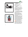
GB
OPERATING INSTRUCTIONS OIL-FREE
COMPRESSORS MARATHON
www.duerr-technik.com
9000-607-28GB/01.09
The information in this document can be
altered without prior announcement. No
part of these pages may be duplicated or
used, for any purpose, without prior written permission of the company, Dürr
Technik; either electronically or mechanically.
© 2007 by Dürr Technik
All rights reserved.
The use of brand name, trade name,
trademark etc. in this manual is covered
by trademark protection legislation and
must not be assumed to be free to use.
These operating instructions correspond
with the technical standard of our products, subject to alteration and errors
accepted.
2
The present operating instructions give
you all the necessary advice for the proper
and safe handling of the product.
Please read and carefully observe the
operating instructions to avoid mistakes
and dangerous situations.
The operating instructions are arranged as follows:
Chapter
Planned purpose
Target group
Chapter 1
Gives you safety advice and important
general information for the product.
Installer, operator, qualified
personnel, user
Chapter 2
Contains detailed instructions and advice for the transport, storage, installation and the initial operation of the product.
Operator, installer and qualified personnel
Chapter 3
Contains instruction and advice for safe
technical handling of the product.
User
Chapter 4-5
Gives detailed instruction for cleaning,
maintenance and servicing the product.
Operator, qualified personnel
Appendix
In the appendix you will find important
technical information.
Qualified personnel
3
PREFACE
These operating instructions are valid for
small oil-free compressors Marathon
hereinafter called product.
The operating manual is only valid so
long as your product complies with the
status described within.
These instructions contain all details
required for the transport, installation,
operation, shut-down and maintenance of
these products.
Therefore please read the operating
instructions carefully prior to the first
operation, thus ensuring the safe and
economic application of the products.
When a fault occurs or maintenance is
required which is not dealt with in the
operating manual, You should contact
our qualified personnel.
All service and maintenance work
must be carried out by qualified personnel.
If service and maintenance work is neglected or carried out improperly, our
warranty will be invalidated.
4
Should you have any problems understanding the operating instructions our
qualified personnel will be pleased to
help you.
Dürr Group
Dürr Technik GmbH + Co. KG
Pleidelsheimer Straße 30
74321 Bietigheim-Bissingen
Telefon 0 71 42 / 90 22 0
Telefax 0 71 42 / 90 22 99
CONTENT
1.
Introduction and general advice ..6
1.1
Symbol explanation and definition..6
1.1.1 Symbol explanation..........................6
1.1.2 Definitions..........................................6
1.2
General safety advice......................6
1.3
Product description ..........................8
1.3.1 Agreed application ...........................8
1.3.2 Function description of the product 8
1.3.3 Supply schedule / Spare parts........8
2. Transport, Storage,
Initial operation..............................9
2.1
Transport and storage .....................9
2.2
Transport and storage
requirements.................................. 10
2.3
Assembly advice and initial
operation ........................................ 10
2.3.1 Environmental conditions ............. 10
2.3.2 Vibration damping ......................... 11
2.3.3 Assembly position ......................... 11
2.3.4 Electrical installation...................... 12
2.3.5 Motor protection............................. 12
2.3.6 Protection type............................... 13
2.3.7 Direction of rotation ....................... 13
3.
Operating: Small oil-free
compressor..................................13
3.1
Compressed air connection......... 13
3.2
Suction filter.................................... 13
3.3
Start against pressure................... 13
3.4
Limiting the operating pressure .. 13
4.
Cleaning .......................................13
5.
Maintenance.................................14
5.1
Filter change .................................. 14
Appendix .............................................15
Appendix 1: Technical data .......................15
Appendix 2: Dimensions............................16
Appendix 3: Manufacturers Certificate .....18
Appendix 4: Trouble shooting ...................19
Appendix 5: Exploded diagram.................21
Appendix 6: Parts list..................................22
Appendix 7: Accessories list......................22
Appendix 8: Addresses..............................24
Appendix 9: Index.......................................25
5
1. INTRODUCTION AND
GENERAL ADVICE
1.1
Symbol explanation and
definition
1.1.1 Symbol explanation
In the manual and on the product hand
symbols and pictograms are used whose
meaning you should memorise. These
symbols help you to understand the
information in this manual quicker and
make you aware of potential danger or
important advice.
Attention! Danger sign. It points out
danger as well as rules and bans to
prevent personal and /or danger to
property.
Advice! Attention is brought to
advise on the handling and economic use of product.
Warning against electric energy!
Your life could be in danger. Make
sure that all electrical work is carried
out by a qualified electrician.
Warning advice. The product can
start without warning!
Warning of hot surfaces! There is
a danger of burns! Observe especially that these surfaces may still be
hot after the product has been
switched off. Work near these surfaces only after they have cooled
off.
1.1.2 Definitions
User, Operator: The responsible Person
who has the authorisation to use the
product. The user must have been given
instructions on the safe handling of the
unit from the appropriate authority.
Operator Authority: Responsible for the
safe installation, regular servicing and
cleaning of the product.
Qualified personnel: Trained by the
operating authority or by authorised Dürr
Technik personnel who are aware of the
dangers of the product and familiar with
the technical aspects of the product.
Qualified personnel are trained to carry
out service and repair on the product.
Product: General term used for oil-free
compressors Marathon.
1.2 General safety advice
During use, care and maintenance of the
product, the following fundamental safety
measures must be observed for the protection of the operator, maintenance and service engineers as well as the product:
During the development and
manufacture of the product,
the recognised regulations of
the technical aspects, as well
as the recognised valid standards and
guidelines were taken into account and
used. In addition the product has been
designed and constructed in such a way
that endangerment through the agreed
use are minimized. Nonetheless we feel
obliged to describe the following safety
measures so the remaining dangers can
also be minimized.
Warning! When electrical equipment is being used, the basic safety
precautions must be followed, to
prevent risk of fire, electric shock
and personal injury.
6
Therefore please read the manual
to hand, prior to starting work. Keep
this manual within reach for the
engineer and the operator. The
information should be passed on to
any successor.
During operation of the products the
relevant laws and regulations for the
place of deployment must be observed!
In the interest of safe operation the
authorised operator and the supervisory
personnel are responsible for keeping
within the regulations.
Check during all work on the product for
possible dangers. All parts must be correctly fitted and all requirements fulfilled
to ensure safe operation. Should the
product be damaged in any way, the
product should no longer be used. The
product should only be repaired by experts. Mark the defect clearly and pull out
the mains plug, so that until the repair is
effected, no accidents or damage can
occur through the defective product.
thoroughly whether lines or cables are
damaged. If there is damage, do not
operate the product.
If there is damage, do not operate
the product. Pull out mains plug!
For all maintenance and repair work the
mains plug must be pulled out of the
socket.
Attention! Work on electrical equipment must only be carried out by a
qualified electrician.
Only original spare parts must be used.
Otherwise there may be injury to the
user.
Warning! The use of other spare
parts and other accessories, as
stated in this manual, can cause
personal injury. Only use spare
parts permitted by the manufacture!
Take account of environmental
influences! Do not operate the
product in a wet or damp environment.
Do not use the power connection line for
purposes it was not meant for. Do not pull
the plug out of the socket by the cable.
Only pull the plug from the socket by
pulling the plug casing. Protect the cable
against heat, oil and sharp edges.
In dangerous situations or during
technical problems, separate the
product at once from the power
supply (pull the plug).
Check regularly the power supply cable
and the casings of electrical components
and if they are damaged, have them
repaired by a qualified electrician.
Check the electrical equipment for external damage before work starts. Check
7
1.3
1.3.1
Product description
Agreed application
The product is intended for the compression of air and non-aggressive gases.
The aspiration of fluids, aggressive or explosive gases is forbidden! It will cause danger to health
and the possible danger of explosion or fire!
The product is designed for use with
equipment or in a unit.
It should only be used if the manufacturer
of the equipment or unit, in which the
product is to be incorporated, has ensured that all requirements for safe operation have been fulfilled.
The product is designed for operation in
dry, ventilated rooms. These products
must not be operated in a damp or wet
environment. In addition, operating near
gases or flammable liquids is forbidden.
1.3.2 Function description of the
product
The product produces oil-free, filtered
compressed air.
Atmospheric air is aspirated via the suction filter. This air is compressed by the
piston in the cylinder. The inlet or else the
outlet valve cuts off in single flow direction, so that the compressed air is forced
into the compressed airline system.
1.3.3 Supply schedule / Spare
parts
Every production model consists of a
basic model. The spare parts list enables
the completion with a vibration damper
set. These additional parts are shown
with the position numbers in the appendices.
8
2. TRANSPORT,
STORAGE, INITIAL
OPERATION
2.1
Transport and storage
The product is sent from the factory in a
specially padded transport carton. With
this equipment is safe against transit
damage. Always use the original packaging of the product if necessary.
Transport the product in an upright position.
Protect the product during transport
and storage against damp and
extreme temperatures. Take special
care that the electrical equipment
does not get damp or wet.
The products must only be transported pressureless. Remove air
from any fitted pressure containers
and hoses.
The products are delivered for immediate
assembly. Products still in the original
packing can be stored in warm, dry and
dust free rooms. If the products should be
stored long term, e.g. as a replacement
product, it must be protected against dust
and damp.
Keep packaging if at all possible.
Environmental rules regarding the disposal of the packaging must be observed
and to assist this please note the labels
on the packaging.
9
2.2 Transport and storage requirements
Temperature: -25 °C to + 55 °C
Relative humidity: 10% to 90%
(without condensation)
2.3 Assembly advice and initial
operation
The product is designed to be inserted
into units. They should only be fitted by a
trained engineer, who is familiar with any
potential hazards. The product must only
be operated when it has been made
certain that all relevant safety requirements have been fulfilled.
1
2.3.1
Environmental conditions
The product must only be installed
and operated in dry, well ventilated
and dust free rooms.
Take care when choosing the site for
installation that the product is easily
accessible for operating, cleaning and
maintenance. Especially the connection
piece and the operational parts must be
easily accessible.
The product should be installed on a level
and sufficiently solid surface. To reduce
vibration the supplied vibration dampers
should be mounted. If the product is built
into a machine or housing, it must be
noted that the identification plate is visible
and readable, without having to dismantle
the product. Also ensure that the connection clamps are easily accessible when
taking off or opening the housing.
Please observe that the suction
side of the air filter is free.
2
10
When fitting into a housing it should be
observed that the min. distance is kept
(see fig. 1 and 2). It must also be noted,
that there is sufficient ventilation. In certain cases an independent ventilation
system may be required. Please note that
the power line connection and the airlines
are not kinked.
The room temperature must not fall below 5 °C, otherwise problem free operation of the controls of the unit cannot be
guaranteed.
The room temperature must not exceed
40 °C. Room temperatures above 40 °C
will require additional ventilation. Most
suitable ambient temperatures are between 10 °C to 15 °C.
Approx. 70% of the product induced
electrical energy is converted into
heat and is given off to the surrounding area.
The motor ventilator normally ensures
effective pressurised cooling of the product. To do this the air must be able to
flow to and for unhindered. Ventilation
openings must be large enough to allow
this to happen. In unsuitable cases, e.g.
when the product is built-in, an independent air cooling system might be
required.
2.3.2
Vibration damping
The product produces vibrations. To
dampen this, suitable vibration dampers
must be used. Vibration absorbers specially made for these products can be
found in the accessory list.
Please do not use rigid connections
between the product and the pipeline
system.
The wrong kind of vibration dampers or use of rigid connection
can damage the product or the
equipment into which the unit has
been installed.
2.3.3
Assembly position
Products should be installed in the horizontal plane (see fig. 1 and 2).
11
2.3.4
Electrical installation
The connection to the mains voltage supply must only be carried out
by a qualified electrician!
3 Three-phase current / star connection
Observe closely the local regulations for
power undertakings.
The connection must only be carried out
on a power supply with correctly installed
protective conductor.
Please make sure that the connection
cable does not run across the product.
The hot surface of the product could
damage the insulation of the cable.
The electrical connection can be seen in
the electrical diagram (fig. 3 to fig. 5)
respectively the identification in the terminal box.
Fuse protection of the power
circuits against overload and
short circuiting: The power supply
must be protected by all polar fuses
corresponding to the short circuit
current of the motor.
2.3.5
4 Three-phase current /
threeangle connection
Motor protection
To protect the machines from high ambient temperature a temperature switch is
build in at type no. A-080 and A-160.
This prevents an overheating oft the
motor winding. The temperature switch
turns off the machine at undue high ambient temperatures.
In the case of a motor blockade,
for example on running against
pressure or a short circuit in the
motor winding there is such a
high current consumption, that
the temperature switch could be
damaged. Such matters can only
be controlled by the installation
of an overload protection.
5 Alternating current
12
The machine starts running again
automatically after cooling down.
No temperature protection is provided by
the manufacturer for type B-080, B-160,
A-234 and B-304.
2.3.6
Protection type
The various basic models have protection
type IP54 (see technical data page 15).
The products must only be built-in or
used individually corresponding to their
protection types.
2.3.7
Direction of rotation
The units are equipped with fans which
are independent of the direction of rotation. By this reason an instruction for the
direction of rotation is not necessary.
3. OPERATING: SMALL
OIL-FREE COMPRESSOR
It is important to note that the
product has hot surfaces. There
is a danger of being burnt if these
surfaces are touched.
The products are designed for a nominal
value of 10 bar.
3.1
Compressed air connection
The compressed air connection is on the
back of the crankcase.
During product operation high surface
temperatures and vibration can occur.
For this reason we recommend a flexible,
armoured pressure hose partially included in the production range (please
see our accessories list).
Rigid connections lead to damage! Please use for connection an
armoured pressure hose.
3.2 Suction filter
To preserve the life-span of the product,
a suitable suction filter (noise damper)
must be fitted. You will find a choice in
the accessories list.
The air filter is plugged into the cylinder
head.
Inclusive with original delivery.
3.3 Start against pressure
The majority of products do not start
against pressure.
In this case the compressed-air
piping must be exhausted before
each start (e.g. via a mechanical
exhaust valve in the pressure switch
or through a solenoid valve).
3.4 Limiting the operating pressure
The pressure is a decisive factor in the
life-span of the product. It is therefore
recommended to work with the minimum
pressure required.
As the end pressure of the product is substantially higher than
the nominal value, the system
should be protected against excessive pressure, e.g. with a
safety valve.
4. CLEANING
For faultless function it is necessary to
keep the product clean.
The product has hot surfaces.
Allow the product to cool down
before commencing any cleaning
procedure.
Clean the surfaces of the product with a
fluff free cloth. Keep especially the ventilation openings of the crankcase chamber and the cylinder head free from dust
and dirt.
13
5.
MAINTENANCE
The product has hot surfaces. Let
the product cool off before starting any maintenance work.
5.1
Filter change
Prior to changing filter switch off
mains and pull out the plug!
The maintenance interval of the suction
filter or the exhaust filter depends mainly
on the dust content of the aspirated material, the inserted filter and the insertion
conditions. The filter must be changed at
least once a year. Depending on ambient
conditions the change may be more
frequent.
6
14
Note
Dirty filters reduce the delivery
output!
APPENDIX
Appendix 1:
Technical data
min
A-080
5150-10050DT
80
60
no
68
73
800
980
4,3
4,4
B-080
5150-10060DT
80
60
yes
68
73
800
600
4,4/3,0
2,5/1,8
A-160
5250-10050DT
160
115
no
71
76
1300
1600
6,3
7,0
B-160
5250-10060DT
160
115
yes
72
75
1400
5,4/4,4
3,1/2,5
A-234
5350-10050DT
230
165
no
78
1900
8,1
B-304
5450-10060DT
290
230
yes
77
79
2200
2950
7,6/8,3
4,4/4,8
1)
*
•
•
-1
Protection type
A
Weight
Motor
P1(W)
Frequenzy
Current consump-tion 1)
dB(A)
Voltage
Motor wattage
l/min
Sound level
Delivery Pe 5 bar*
l/min
Start against
pres-sure
Delivery 0 bar
Type
Art-No.
Nominal data
V
Hz
kg
IP
50
60
24,5
54
24,5
54
26
54
26
54
45,5
54
47
54
1440
1~230
1710
1460 3~230 50/60
1500 3~400 50/60
1300
1~230
1600
50
60
1410 3~230 50/60
1690 3~400 50/60
1350 1~230
50
1440 3~230 50/60
1700 3~400 50/60
current at nominal voltage
Delilvery at 50 Hz according to ISO 1217 referring to the suction condition (at 60 Hz approx. + 18%)
All models are for S1-operation = 100% duty rating.
PS = Safety pressure, max. allowable pressure
Since our products are subject to a process of continuous improvement, the technical specification may have changed. If you propose to base your planning on these
Directions for Use, please contact us beforehand for details of current data and
dimensions.
15
Appendix 2: Dimensions
Type
Art.-No.
5150-100-50DT
5150-100-60DT
5250-100-50DT
5250-100-60DT
5350-100-50DT
5450-100-60DT
l
b
h
423
423
423
423
620
620
193
180
350
350
350
350
330
300
300
300
315
315
h
A-080
B-080
A-160
B-160
A-234
B-304
b
l
h
A-080 / B-080
l
A- 160 / B-160
16
b
h
l
b
h
A-234
l
b
B-304
17
Appendix 3: Manufacturers Certificate
MANUFACTURER’S CERTIFICATE FOR MACHINES
98 / 37 EEC annex II, B
Manufacturer:
Dürr Technik GmbH & Co. KG
Adresse:
Pleidelsheimer Str.30
D-74321 Bietigheim- Bissingen
Reference number:
Marathon
Product name:
Kompressor
Starting with serial number:
V 000001
Herewith we declare that prior to initial operation, it must be determined that the machine in
which this machine is to be installed, conforms to the stipulations of the applicable machine
directive, 98/37/EEC
Directive for low voltage 73/23/EEC
Directive electromagnetic compatibility EMC 89/336/EEC
Following harmonized standards are applied
EN 1012-1:1996-07
EN 1012-2:1996-07
EN 60335-1:2007-02
EN 50106:2001-08
EN 60034-1:2005-04
EN 60034-5:2001-12
EN 55014-1,2:2002-08
Bietigheim- Bissingen, date 24.04.07
ppa. A.Ripsam
Vice President Dürr Technik
18
Signatures registered with original document
Dürr Technik archive
Appendix 4:
Trouble shooting
The following description for fault finding is only meant for authorised
personnel. Repairs must only be carried out by authorised personnel.
Fault
Possible cause
Remedy
•
Mains voltage failure
•
•
•
•
Low voltage
Defective capacitor
•
•
•
Mains voltage compared to rated current
too high
•
•
Mains voltage compared to rated current
constant
•
•
•
•
•
Suction filter blocked
Sluggish mechanically
Pressure in line
Overcurrent switch has
actuated
Lamellar valve (inlet
valve resp. outlet valve)
between cylinder and
cylinder head defective
Leakage in pressure
hose system
•
•
•
•
Compression cover at
the piston used up
•
•
Appliance
does not start
•
Appliance
does not
switch off
•
•
Check mains voltage
Check mains fuse, if necessary
switch on appliance again (if indicating fuse defective, change it).
Check mains voltage
Check capacitor if necessary change
it
under/overvoltage: measure voltage
if necessary call electrician
Appliance mechanically sluggish,
piston get stuck (protective motor
switch): Pull out mains plug, take off
crankcase cover of warmed up appliance and spin ventilator wheel; if
not possible change piston and cylinder or complete appliance
Overcurrent switch set too low: (see
technical data) measure current.
Overcurrent switch defective:
check overcurrent switch,
Insert new filter
Factory repair
Ventilate air intake
Remedy cause
•
Dismount cylinder head and install
new lamellar valve
•
Impinge pipe system with pressure, if
necessary seek leakage with spray
and seal up
Change piston and cylinder or complete appliance
19
Fault
Possible cause
Remedy
Appliance
starts occasionally without consumer
air tapping
•
Leakage
•
•
Lines, hoses or connec- •
tions leaking
Suction filter very dirty •
•
Decrease in
delivery performance
•
•
•
Noise level too
high
20
•
•
•
Cylinder head seal
defective
Lamellar valve
(inlet/outlet valve) defective
Compression cover at
the piston used up
Bearing damaged
Vibrations transmitted
to the housing
Defective anti vibration
damper
•
Seek leakage and seal up
Check lines, hoses and connections (if
possible, seal otherwise replace)
Change suction filter annually, do not
clean, if necessary insert filter with
greater filter surface
Change seal
•
Change lamellar valve and if necessary, valve plate and seals
•
Change piston and cylinder or complete appliance.
Werksreparatur
Fit suitable anti vibration dampers
(see accessory list)
Fit new anti vibration damper
•
•
•
10
12.1
10.1
11.3
11.2
11.1
11
8.2
8.3
13.2
16.1
12 13.1
13
15
14
1
16
8.1
8
9.1
9.2
9.3
9
6
7
6.1
5
4
3
2
2.1
30
8.4
31
20.1
22.1
24
25
Appendix 5: Exploded diagram
21
Appendix 6: Parts list
Pos.
No.
Description
A-080
5150-100-50DT
B-080
5150-100-60DT
A-160
5250-100-50DT
1
Suction filter
1x 9000-416-38
1x 9000-416-38
2x 9000-416-38
spare parts kit sealing set
1x 5150-981-00
1x 5150-981-00
2x 5150-981-00
-
-
-
by request
-
by request
3,5,7
30
20.1
Pressure hose
Capacitor
Appendix 7: Accessories list
Pos.
No.
22
A-080
5150-100-50DT
B-080
5150-100-60DT
A-160
5250-100-50DT
Vibration damper set
5150-982-52
5150-982-52
5150-982-53
Pressure switch
with G1/4“ external thread
9000-301-58
9000-301-58
9000-301-58
overcurrent switch
(only usable with pressure
switch)
by request
by request
by request
Safety valve 10 bar
with G1/4“ external thread
(approved)
9000-326-20/X
9000-326-20/X
9000-326-20/X
Description
B-160
5250-100-60DT
A-234
5350-100-50DT
B-304
5450-100-60DT
2x 9000-416-38
3x 9000-416-38
4x 9000-416-38
2x 5150-981-00
3x 5150-981-00
4x 5150-981-00
-
1x 5351-002-00
1x 5351-002-00
-
by request
-
B-160
5250-100-60DT
A-234
5350-100-50DT
B-304
5450-100-60DT
5150-982-53
0881-991-00
0881-991-00
9000-301-58
9000-301-58
9000-301-58
by request
by request
by request
9000-326-20/X
9000-326-20/X
9000-326-20/X
23
Appendix 8:
Addresses
Technical advice
Dürr Technik GmbH + Co. KG
Pleidelsheimer Straße 30
74321 Bietigheim-Bissingen
Telephone +49 (0) 71 42 / 90 22 - 0
Fax
+49 (0) 71 42 / 90 22 - 99
www.duerr-technik.de
Dürr Technik (UK) Ltd.
Unit 5 Ashmead Business centre
Ashmead Road
Keynsham
Bristol
BS31-1SX
Telephone 0117 9860414
Fax
0117 9860416
[email protected]
Dürr Technik Sverige AB
Box 302
S-571 24 Nässjov
Telephone 0380 - 55 49 80
Fax
0380 - 743 15
Spare parts service
Spare part orders to be sent in accordance
with the existing spare parts list in writing, to
the above address or by telephone to the
following number
Telephone +49 (0) 71 42 / 90 22-31
Fax
+49 (0) 71 42 / 90 22-99
[email protected]
For ordering spare parts the following details
are required:
•
•
•
•
•
24
Model no. and article no.
Order no. as per parts list
How many of each item required
Exact address to dispatch to
Dispatch details
Repairs / return delivery
When returning products, if possible, use the
original packing. Always pack the product in
synthetic packaging material. If possible use
recyclable packing material.
Appendix 9: Index
A
Accessories list 22
Addresses 24
Advice 6
Agreed application 8
Alternating current 12
Appendix 15
Assembly advice 10
Attention 6
C
Cleaning 13
D
definition 6
Dimensions 16
Direction of rotation 13
E
Environmental conditions 10
Exploded diagram 21
M
Maintenance 14
Manufacturers Certificate 18
Motor protection 12
O
Operating 13
Operator 6
P
Parts list 22
Product 6
Product description 8
Protection type 13
Q
Qualified personnel 6
R
Repairs / return delivery 24
G
general advice 6
General safety advice 6
S
Sound level 15
Spare parts service 24
Start against pressure 13
Storage 9
storage requirements 10
Suction filter 13
Symbol explanation 6
I
T
Initial operation 9
Introduction 6
Technical data 15
Three-phase current / star connection 12
Three-phase current /
threeangle connection 12
Transport 9
Trouble shooting 19
F
Filter change 14
Function description 8
L
Limiting the operating pressure 13
U
User 6
V
Vibration damping 11
25
26
27
Dürr Technik GmbH + Co. KG
Postfach 1129 • 74301 Bietigheim-Bissingen
Pleidelsheimer Straße 30 • 74321 Bietigheim-Bissingen
Tel. (+49) 71 42/90 22-0 • Fax (+49) 71 42/90 22-99
Internet: www.duerr-technik.com
E-Mail: [email protected]
DÜRR TECHNIK Sverige AB
Box 302 • S-571 24 Nässjô
Tel.: (+46) 3 80 / 55 49 80 • Fax: (+46) 3 80 / 7 43 15
eMail: [email protected]
DÜRR TECHNIK (UK) Ltd
Ashmead Road, Keynsham • UK-Bristol
Tel.: (+44) 117/9 86 04 14 • Fax:(+44) 117/9 86 04 16
eMail: [email protected]
DÜRR TECHNIK France S.A.R.L.
26, rue Diderot • F-92000 NANTERRE
Tel.: (+33) 1 55/69 11 80 • Fax:(+33) 117/69 11 81
eMail: [email protected]