1
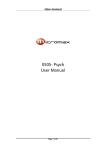
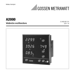
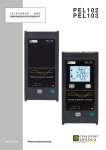
Operating Instructions
Multifunctional Power
Monitor with System Analysis
SINEAX A 230 / A 230s
Camille Bauer LTD
Aargauerstrasse 7
CH-5610 Wohlen/Switzerland
Phone +41 56 618 21 11
Fax +41 56 618 21 21
[email protected]
www.camillebauer.com
A 230 / A230s Be
154 807-10
03.13
The instruments must only be disposed of in the
correct way!
Safety notes
The installation and commissioning should only be carried out by trained
personnel.
Check the following points before commissioning:
– that the maximum values for all the connections are not exceeded, see
the “Technical data” section,
– that the connection wires are not damaged, and that they are not live
during wiring,
– that the power flow direction, and the phase rotation are correct.
The instrument must be taken out of service if safe operation is no longer possible (e.g. visible damage). In this case, all the connections must
be switched off. The instrument must be returned to the factory or to an
authorized service dealer.
It is forbidden to open the housing and to make modifications to the instrument. The instrument is not equipped with an integrated circuit breaker.
During installation check that a labeled switch is installed and that it can
easily be reached by the operators.
Unauthorized repair or alteration of the unit invalidates the warranty.
Contents
Page
Brief description
2
Technical data
2
Commissioning
3
Electrical connections
3
Measured value display
5
Operation
9
Display window
10
Programming
13
Programming charts
20
Dimensional drawing
22
1
Brief description
Uext
Panel mounting instrument A230 with dimensions 144x144x46 mm
resp. A230s with dimensions 96 x 96 x 46 mm. Four-quadrant measurement for power system and consumption analysis in single and
multi-phase AC systems. Three large LED displays with four digits
plus sign. The converter data are included for direct display and
further processing. Configurable display settings for user specific
presentation, integrated energy meters, impulse counters, and limit
value indication. Comprehensive average value and max./min. value
functions. Harmonic analysis and THD measurement. Determination
of the neutral wire current. Asymmetry factor and neutral point voltage shift. Two switched outputs for the control of impulse counters,
or for signalling limit alarms.
Technical data
(for more detailed information please see datasheet, download under
www.camillebauer.com)
20
SO2
U
RL
e.g. energy import
t
21
SO1
RL
U
e.g. limit value output
22
Limit value outputs
The measured values can be freely allocated.
Pulse outputs
Active and reactive energy pulses can be generated for the control
of electronic and electromechanical counters.
Power supply
Measuring inputs
Nominal frequency:
50, 60 Hz
Nominal input voltage:
Phase-phase: 500 V
Phase - N: 290 V
Nominal input current:
5 A or 1 A
DC-, AC power pack 50 to 400 Hz
100 to 230 V AC/DC ±15% or 24 to 60 V AC/DC ±15%
(UL) 85 bis 125 V DC
Power consumption:
3 VA (without extension module)
A marked and easily accessible current limiting
switch has to be arranged in the vicinity of the device
for turning off the power supply. Fusing should be
10 Amps or less and must be rated for the available
voltage and fault current.
Continuous thermal rating of inputs
10 A at 346 V in single-phase AC system
10 A at 600 V in three-phase system
Reference conditions
acc. to IEC 688 resp EN 60 688
Short-time thermal rating of inputs
Sine 50 - 60 Hz, 15 - 30°, application group II
Input variable
Number of
inputs
Duration
of
overloads
577 V LN
10
1s
10 s
100 A
10
1s
100 s
100 A
5
3s
5 min
Interval between
two overloads
Measurement accuracy (related to nominal value)
Current, voltage
Power
Power factor
Energy
Frequency
Environmental conditions
Measuring ranges
U, I, S:
≤ 120% of nominal value
P, Q:
≤ ± 120% of nominal value
F:
45 to 65 Hz
cosϕ:
±1
Operating temperature:
Storage temperature:
Humidity relative:
Altitude:
Indoor use statement
The measurement display is 4 digit (frequency) and right justified.
Energy values are displayed with 8 digits.
Zero value suppression
PF resp cosϕ:
Display ---, if Sx < 0.2% Snenn
Currents:
Display 0, if Ix < 0.1% Inenn
unb. U:
Display 0, if Ø U < 5% Unenn
Protection class:
Measuring category:
Pollution degree:
Measurement voltage:
Test voltage:
Pulse/Limit value outputs
Depending on the function selected, the two digital outputs can
be used either as pulse outputs for actual and reactive energy or
as limit signals.
The outputs are passive, and are galvanically isolated from all the
other circuits by opto-couplers. They are suitable to drive tariff
devices (S0-standard DIN 43 864), or 24 V relais.
2
-10 to +55 °C
-25 to +70 °C
≤ 75%
2000 m max.
Safety
Display
Uext
IL
± 0.2%
± 0.5%
± 0.5%
± 0.5%
± 0.02 Hz (abs.)
≤ 40 V DC (OFF: leakage current ≤ 0.1 mA)
≤ 150 mA (ON: terminal voltage ≤ 1.2 V)
II (voltage inputs with protection
impedances)
III
2
300 V
Between current inputs, power
supply, digital outputs, terminals
of the plugged-in module: 3700 V /
50 Hz / 1 min.
On voltage inputs:
4.25 kV 1.2/50 μs
Module connections:
The pin rail at the back is connected
to the voltage inputs via a protection impedance. Only the permitted
modules can be plugged-in!
Enclosure protection:
IP 20
Commissioning
Symbol
The multifunctional power monitor is made operational by switching
on the power supply. The following appears sequentially on the
display:
Meaning
Device may only be disposed of in a professional
manner!
1. Segment tests: all the segments of the displays and all the LEDs
are lit for 2 s.
2. Version of the software: e.g. A 230
1.04
3. The 3 line voltages at switching on.
Double insulation, device of protection class 2
CE conformity mark. The device fulfills the requirements of the applicable EC directives.
Loss of the power supply
Products with this mark comply with both the
Canadian (CSA) and the American (UL) requirements
All the values configured remain during a loss of the power supply.
On reconnecting the power supply, the last mode selected is displayed.
Caution! General hazard point. Read the operating
instructions.
Note of maintenance
No maintenance is required.
General symbol: Input
Electrical connections
General symbol: Output
Safety Disconnects
General symbol: Power supply
The mains supply power to the instrument must be
installed downstream from a switched current limiting
device.
The circuit protection device should be 20 Amps or
less, and must be rated for the available voltage and
fault current; 5 Amp fuses are preferred.
CAT III
Measurement category CAT III for current and voltage inputs
WARNING
All mains supply power to the instrument must be
installed downstream from a switched current limiting
device.
The circuit protection device should be 20 Amps or
less, and must be rated for the available voltage and
fault current; 5 Amps are preferred.
The national provisions (e.g. in Germany VDE 0100
“Conditions concerning the erection of heavy current
facilities with rated voltages below 1000 V”) have to
be observed in the installation and material selection
of electric lines!
Connecting modes
System/
application
Terminals
2
11
1
2
3
11
1
3
k
When using external PT’s or CT’s refer to the
manufacturer’s information for connections for voltage and current monitoring.
Single phase
AC system
L1
L1
N
N
2
11
u
The electrical connections are identical for the SINEAX A 230 and
A 230s.
1
l
K
L
3
v
k
U
l
V
L1
K
L
N
2
Measuring input, acc. to measuring mode
I1
U1
I2
U2
I3
U3
8
5
3
1
2
L1
L2
L2
5
U2
6
I2
7
I3
UL: 3~300V
5A 50/60Hz CAT III
IEC: 3~500/290V 5A 50/60Hz CAT III
SINEAX A230s Ord: 010/123456/010/001
Man: 10/02
230S-121200
NLBxxxx
SO
1 2
22 21 20
8
U3
9
I3
11
N
Camille Bauer AG
Switzerland
100-230V AC
85-125V DC
50-400Hz 3VA
LOCK
3-wire
3-phase
symmetric
load
I: L1
K
l
L
L3
2
4
I2
3
1
k
L1
L3
3
I1
8
N
No. 1
1 2
I1 U1
5
8
5
3
1
u
v
u
v
U
V
U
V
k
L1
K
l
L
L2
L3
14 15
Connect the voltage according to the following
table for current measurement in L2 or L3:
1 2 +
Pulse /
Limit value output
Jumper
Power supply
Current
transf.
Terminals
2
5
8
L2
1
3
L2
L3
L1
L3
1
3
L3
L1
L2
3
System/
application
System/
application
Terminals
11
2
1
2
3
11
1
3
k
4-wire
3-phase
symmetric
load
I: L1
Terminals
l
L1
L2
L2
L3
L3
L3
N
N
N
2
11
u
1
4-wire
3-phase
asymmetric
load
v
U
l
V
L1
L2
K
8
11
1
3
4
2
5
8
11
1
3
4
6
9
7
L2
L
3
k
5
L1
L1
K
2
L
k
6
l
k
L1
9
7
K
l
L
L2
k
K
l
L
L3
K
L
N
L3
N
2
Connect the voltage according to the following
table for current measurement in L2 or L3:
Current transf.
Terminals
2
11
L1
L2
1
3
L2
N
L3
L3
1
3
L3
N
8
5
1
11
u
u
u
x
x
x
X
X
X
U
U
U
4
3
k
6
9
7
l
k
K
l
L
L2
k
K
l
L
K
L
N
3 single-pole insulated voltage transformers
in high-voltage system
2
1
8
5
4
3
6
9
7
2
1
11
8
k
L1
4
3
6
l
k
L2
L1
L3
L2
9
7
K
l
L
k
K
l
L
L3
K
L
N
2
3-wire
3-phase
asymmetric
load
1
8
5
4
3
k
6
4-wire
3-phase
asymmetric
load,
Open-Y
l
k
L1
9
7
K
l
L
k
L2
K
l
L
L3
K
Low-voltage system
1
L
2
3
4
5
7
6
8
9 11
u u
x x
k
X X
2
8
5
u
u
1
11
4
3
6
9
7
L1
u
x
x
x
X
X
X
U
U
U
L2
L3
L1
k
K
l
L
L2
k
K
K
3-wire
3-phase
asymmetric
load,
Aron
8
5
3
1
2
8
5
3
1
k
L1
L1
L2
L2
L3
L3
2
8
5
3
1
u
v
u
v
U
V
U
V
k
L1
4
9
7
K
l
L
k
l
L1
L2
L2
L3
L3
K
L
9
7
l
K
L
k
l
K
2
9
7
l
L
L
K
L
K
L
2 single-pole insulated voltage transformers
in high-voltage system
L
3 single-pole insulated voltage transformers in
high-voltage system
2
K
l
L
L3
k
l
N
l
k
k
l
UU
8
5
3
1
u
u
u
x
x
x
X
X
X
U
U
U
k
K
L
9
7
l
k
L
K
l
L
Measured value display
7-segment
top
7-segment
centre
k:
Kilo
M: Mega
M+k: Giga
7-segment
bottom
cos-Phi
Maximum
Average value
Sign
Sum or system
value
Minimum
Right LED
group
Left LED
group
Bimetal symbol (I-avg)
Delta voltage
Integration symbol
(interval average value)
P
Display
2 3
Clear
Phase 3
Phase 2
Phase 1
Bottom LED group
Abbreviations and symbols
οΛ
Υ.νΕ
υνβ.Υ
ιν
ΣΨΣτ.
ξ.ξξ ι
ξ.ξξ χ
− ξ.ξξ ι
− ξ.ξξ χ
ινχ
ουτ
ινδ
ΧΑΠ
.Η
.Λ
τηδ.Υ
τηδ.ι
τρνδ
τ−0…τ−4
Η2.Υ…Η15.Υ
Η2.ι…Η15.ι
Overload, out of range indicator
Neutral point voltage shift (U neutral-earth)
Voltage asymmetry factor (unbalance U)
Neutral current
System power
ϕ
Power factor incoming inductive
ϕ
Power factor incoming capacitive
ϕ
Power factor outgoing inductive
ϕ
Power factor outgoing capacitive
Incoming
Inductive
Capacitive
Energy high tariff
Energy low tariff
THD-U
THD-I
Interval power: Trend
Interval power: last to fifth last interval
2nd - 15th harmonic U
2nd - 15th harmonic I
Outgoing
Available measurement data
(at connection mode 4-wire asymmetric load)
(t
LED
group
left
c b)
Phase voltages: U1, U2, U3
Maximum values: U1-max, U2-max, U3-max
Minimum values: U1-min, U2-min, U3-min
Delta voltages: U12, U23, U31
Maximum values: U12-max, U23-max, U31-max
Minimum values: U12-min, U23-min, U31-min
Neutral point voltage shift: UNE and UNE-max
Voltage asymmetry factor (unbalanced U)
Phase currents: I1,I2, I3
Maximum values: I1-max, I2-max, I3-max
Average values: I1avg, I2avg, I3avg
(bimetal-15minutes)
Max. average values: I1avg-max, I2avg-max,
I3avg-max (slave pointer -15 minutes)
Neutral current: IN and IN-max
Active power: P1, P2, P3
a)
Maximum values: P1-max, P2-max, P3-max
a)
Example
7-segm.
display
top
Example
7-segm.
display
centre
Example
7-segm.
display
bottom
230.2
235.1
227.8
400.0
405.2
395.5
Υ.νΕ
υνβ.Υ
11.54
12.65
7.23
231.1
236.4
226.6
402.5
406.4
397.4
2.3
1.4
10.98
11.86
6.86
229.9
231.2
225.7
398.4
403.3
396.8
8.6
6.2
10.23
11.07
6.46
7.98
ιν
2240
2554
LED
group
right
LED
group
bottom
V
L1
L2
L3
V
L1
L2
L3
V
L1
L2
L3
V
Δ
V
Δ
V
V
%
A
L1
L2
L3
A
L1
L2
L3
A
L1 L2 L3
7.48
6.98 A
L1 L2 L3
1.13
2032
2825
2.75 A
1491 W
2482 W
L1
L2
L3
L1
L2
L3
Continuation see next page!
5
Example
7-segm.
display
top
Example
7-segm.
display
centre
Example
7-segm.
display
bottom
ΣΨΣτ.
1078
1704
ΣΨΣτ.
2281
3066
ΣΨΣτ.
0.82χ
5.76
393
561
2.19
2157
2874
6.64
0.97χ
7.86
721
1027
3.29
2089
2682
8.11
0.92χ
a)
0.90χ
ι
0.72χ ϕ
a)
0.90χ
ι
χ ϕ
50.14
4589
1234
4589
1234
9876
1234
76
234
9876
1234
76
234
5.76
230.4
0.90χ
5.76
2240
2032
1491
230.2
231.1
229.9
τηδ.Υ
τηδ.Υ
τηδ.Υ
τηδ.Ι
τηδ.Ι
τηδ.Ι
Π.ινχ
50.03
2356
5678
2356
5678
5432
9876
5432
9876
5432
9876
5432
9876
2.19
10.92
5.76
6.64
1078
393
721
11.54
10.98
10.23
2.5
2.6
2.4
2.4
2.5
2.4
5.23
Π.ινχ
6.02
1.56 kW ∑
Interval active power: last interval (t-0) incoming
to
fifth last interval (t-4) incoming
Π.ινχ
3.91
τ 0 kW ∑
Π.ινχ
5.52
τ 4 kW ∑
Interval active power: Trend-outgoing
Π.ουτ
0.00
τρνδ kW ∑
Interval active power: Maximum-outgoing
Minimum-outgoing
Π.ουτ
0.00
0.00 kW ∑
Π.ουτ
0.00
τ 0 kW ∑
Π.ουτ
0.00
τ 4 kW ∑
Available measurement data
(at connection mode 4-wire asymmetric load)
(t
LED
group
left
c b)
Active power system: P and P-max
a)
Reactive power: Q1, Q2, Q3
b)
Maximum values: Q1-max, Q2-max, Q3-max
b)
Reactive power system: Q and Q-max
b)
Apparent powers: S1, S2, S3
Maximum values: S1-max, S2-max, S3-max
Apparent power system: S and S-max
Power factors: PF1, PF2, PF3
a)
PF-system, PF-min-inductive-incoming,
PF-min-capacitive-incoming
PF-system, PF-min-inductive-outgoing,
PF-min-capacitive-outgoing
Frequency: F-max, F-actual, F-min
Active power incoming EP high tariff
Active power incoming EP low tariff
c)
Active power outgoing EP high tariff
Active power outgoing EP low tariff
c)
Reactive power inductive EQ high tariff
d)
Reactive power inductive EQ low tariff
c) d)
Reactive power capacitive EQ high tariff
d)
Reactive power capacitive EQ low tariff
c) d)
Reactive power incoming EQ high tariff
e)
Reactive power incoming EQ low tariff
c) e)
Reactive power outgoing EQ high tariff
e)
Reactive power outgoing EQ low tariff
c) e)
P-system, Q-system, S-system
Average U1-U2-U3, average I1-I2-I3, P-system
PF-system, P-system, Q-system
P-system, S-system, frequency
P1, Q1, S1
P2, Q2, S2
P3, Q3, S3
U1, I1, P1
U2, I2, P2
U3, I3, P3
THD-U1, THD-U1-max
THD-U2, THD-U2-max
THD-U3, THD-U3-max
THD-I1, THD-I1-max
THD-I2, THD-I2-max
THD-I3, THD-I3-max
Interval active power: Trend-incoming
Interval active power: Maximum-incoming
Minimum-incoming
Interval active power: last interval (t-0) outgoing
to
fifth last interval (t-4) outgoing
Continuation see next page!
6
49.78
ινχ.Η
ινχ.Λ
ουτ.Η
ουτ.Λ
ινδ.Η
ινδ.Λ
ΧΑΠ.Η
ΧΑΠ.Λ
ινχ.Η
ινχ.Λ
ουτ.Η
ουτ.Λ
6.64
5.76
2.19
50.03
2485
2070
2089
2240
2032
1491
8.0
8.3
3.9
10.8
9.5
4.6
τρνδ
LED
group
right
LED
group
bottom
kW
VAr
L1
L2
L3
VAr
L1
L2
L3
VA
L1
L2
L3
VA
L1
L2
L3
L1
L2
L3
kVAr
kVA
ϕ
Hz
kWh ∑
kWh ∑
kWh ∑
kWh ∑
kVarh ∑
kVarh ∑
kVarh ∑
kVarh ∑
kVarh ∑
kVarh ∑
kVarh ∑
kVarh ∑
kW kVAr kVA
VØ AØ kW
ϕ kW kVAr
kW kVA Hz
W VAr VA
L1
W VAr VA
L2
W VAr VA
L3
V
A
W
L1
V
A
W
L2
V
A
W
L3
%
L1
%
L2
%
L3
%
L1
%
L2
%
L3
kW ∑
to
to
Example
7-segm.
display
top
Example
7-segm.
display
centre
Θ.ινδ
0.00
τρνδ kVAr ∑
Θ.ινδ
0.00
0.00 kVAr ∑
Θ.ινδ
0.00
τ 0 kVAr ∑
Θ.ινδ
0.00
τ 4 kVAr ∑
d)
Θ.χαπ
2.17
τρνδ kVAr ∑
Interval react. power: Maximum-cap.,Minimum-cap. d)
Θ.χαπ
2.53
0.78 kVAr ∑
Interval react. power: last interval (t-0) capacitive
d)
to
fifth last interval (t-4) capacitive
Θ.χαπ
1.41
τ 0 kVAr ∑
Θ.χαπ
1.14
τ 4 kVAr ∑
Θ.ινχ
2.17
τρνδ kVAr ∑
Θ.ινχ
2.53
0.78 kVAr ∑
Interval react. power: last interval (t-0) incoming
e)
to
fifth last interval (t-4) incoming
Θ.ινχ
1.41
τ 0 kVAr ∑
Θ.ινχ
1.14
τ 4 kVAr ∑
Interval react. power: Trend-outgoing
e)
Θ.ουτ
0.00
τρνδ kVAr ∑
Interval react. power: Maximum-outgoing
Minimum-outgoing
e)
Θ.ουτ
0.00
0.00 kVAr ∑
Θ.ουτ
0.00
τ 0 kVAr ∑
Θ.ουτ
0.00
τ 4 kVAr ∑
Interval appar. power: Trend
Σ
5.23
τρνδ kVA ∑
Interval appar. power: Maximum, Minimum
Σ
6.02
1.56 kVA ∑
Interval appar. power: last interval (t-0)
to
fifth last interval (t-4)
Σ
3.91
τ 0 kVA ∑
Σ
5.52
τ 4 kVA ∑
Η2.Υ
0.1
1.2 %
L1
Available measurement data
(at connection mode 4-wire asymmetric load)
(t
Interval react. power: Trend-inductive
d)
Interval react. power: Maximum-inductive
Minimum-inductive
d)
LED
group
left
c b)
Interval react. power: last interval (t-0) inductive
d)
to
fifth last interval (t-4) inductive
Interval react. power: Trend-capacitive
Interval react. power: Trend-incoming
e)
Interval react. power: Maximum-incoming
Minimum-incoming
e)
Interval react. power: last interval (t-0) outgoing
e)
to
fifth last interval (t-4) outgoing
2nd harmonic U1:
15th harmonic U1:
2nd harmonic U2:
15th harmonic U2:
2nd harmonic U3:
15th harmonic U3:
2nd harmonic I1:
15th harmonic I1:
2nd harmonic I2:
15th harmonic I2:
2nd harmonic I3:
15th harmonic I3:
a)
incoming: no sign
LED
group
right
LED
group
bottom
to
to
to
to
to
H2-U1,
to
H15-U1,
H2-U1-max
H15-U1-max
Η15.Υ
0.5
1.8 %
L1
H2-U2,
to
H15-U2,
H2-U2-max
Η2.Υ
0.1
0.4 %
L2
H15-U2-max
Η15.Υ
0.7
2.0 %
L2
H2-U3,
to
H15-U3,
H2-U3-max
Η2.Υ
0.2
1.5 %
L2
Η15.Υ
1.5
2.8 %
L2
Η2.Ι
0.4
2.2 %
L1
Η15.Ι
0.9
4.8 %
L1
Η2.Ι
0.3
1.8 %
L2
Η15.Ι
0.8
5.2 %
L2
Η2.Ι
0.5
3.2 %
L2
1.1
5.8 %
L2
to
to
to
H15-U3-max
H2-I1, H2-I1-max
to
H15-I1, H15-I1-max
H2-I2, H2-I2-max
to
H15-I2, H15-I2-max
H2-I3, H2-I3-max
to
H15-I3, H15-I3-max
Outgoing: sign –
b) incoming inductive, outgoing capacitive: no sign
incoming capacitive, outgoing inductive: sign –
c)
Example
7-segm.
display
bottom
Tariff switching via digital input or controlled via the bus only (optional extension module required)
to
to
to
Η15.Ι
d) only active if the Q definition is set to “ind/cap” (display configuration
7 : Q.tot)
e) only active if the Q definition is set to “inc/out” (display configuration
7 : Q.tot)
7
Determination of measured quantities
The calculation of the measurements is made in accordance with DIN 40 110, with the exception of the reactive power. This is calculated by the
SINEAX A 230/A 230s as a signed value. Transducers and displays can possibly display different values for the reactive power in the same power
system. The reason is the different calculation methods.
Trend values display the predicted value for the current interval.
Example: Power factor 4 quadrant display
PF-L1, PF-L2, PF-L3 actual
(Matrix table 4-wire asymmetric load: field a-6)
Actual power factors per phase:
P
Display
Clear
2 3
top:
PF L1 = incoming / capacitive / 0.352
centre:
PF L2 = outgoing / inductive / 0.875
bottom:
PF L3 = cannot be measured
(---: apparent power < 1% of nominal input power
→ PF cannot be measured
PF-system-actual and PF-min-incoming
(Matrix table 4-wire asymmetric load: field b-6)
top:
PF system actual = outgoing / capacitive / 0.153
(---: apparent power < 1% of nominal input power
PF cannot be measured
P
Display
Clear
centre:
PF minimum incoming inductive = no measuring value
bottom: PF minimum incoming capacitive = 0.352
(minimum: lowest value of PF1, PF2 or PF3)
(---: no measured value in the quadrants concerned)
PF-system-actual and PF-min-outgoing
(Matrix table 4-wire asymmetric load: field c-6)
top:
PF system actual = incoming / ––– / 1.000
(---: apparent power < 1% of nominal input power
→ PF cannot be measured
P
Display
8
Clear
centre:
PF minimum outgoing inductive = 0.486
bottom: PF minimum outgoing capacitive = 0.617
(Minimum: lowest value of PF1, PF2 or PF3)
(---: no measured value in the quadrants concerned)
Operation
Display modes
All the display values in accordance with the matrix
tables can be displayed (factory setting).
Only the pre-configured display values are displayed. The factory pre-configured values are shown
in the matrix tables with a gray-background.
Automatically changing display. The display time,
and the values to be displayed are pre-configurable.
The factory pre-configured values are shown in the
matrix tables with a bold outline. The factory setting
for the display time is 4 seconds.
Changing the display mode
By simultaneously pressing the buttons P and
(display) for
a longer time, the display mode changes and then remains in the
last mode displayed when the buttons are released (factory setting:
FULL). If the mode cannot be changed, the mode lock is switched
on.
Locking
Navigation
X axis
(a, b, c, ...)
For each pressing of the P button, the displayed
value changes in accordance with the preconfiguration and matrix table one window towards the right
and loops back to the beginning.
Y axis
(1, 2, 3, ...)
For each pressing of the
or
buttons, the
displayed value changes in accordance with the
preconfiguration and matrix table one window upwards as far as the top window or respectively one
window downwards as far as the bottom window.
Preferred display
You may select a preferred display which is displayed automatically after a certain time without
user interaction. So the normal appearance of the
device is always the same. There are two different
possibilities to define a preferred display.
Preferred display in Loop mode
In Loop mode a display can be set which should be
displayed normally all the time. In addition, any other
value can be selected as for the full mode. After the
reset time period (2 - 32 s), the display automatically
returns to the preferred display.
In the display configuration menu (Menu Disp),
changing the display modes can be blocked with
the mode lock 16 .
Brightness (13 levels)
brighter
Press the key
for a longer time.
darker
Press the key
for a longer time.
Configuration
The Loop mode is blocked with the mode lock 17 .
The reset time is configured with the display interval
configuration 18 . Set the required window to “on” in
the display configuration under No. 20 (Menu Disp).
Set all the other display elements to “off”.
Simultaneous longer pressing of the
and
buttons (clear)
deletes the max. respectively min. values of the measured value
displayed and the associated values. The energy meters are reset
in the same way.
Preferred display in User-Modus
Locking
Only the User mode is active. Out of the displayable
displays a preferred display can be selected, which
is automatically displayed after a predefined time
without user interaction. All other display contents
may be directly displayed using the keys. The delay
until the preferred display is shown is 4 min. for
version 4.00 resp. 10 min. starting from version 4.01
of the basic device.
Deletion of the max./min. values and meters
The reset function for the energy meters can be
locked by setting the jumper at the rear of the instrument to the position LOCK.
Configuration
The User mode is blocked with the mode lock 17 .
Use the keys to show the display which should serve
as the preferred display and set it as the prefereed
at the
display by pressing the keys P and
same time. The same procedure may be used to
switch-off the preferred display. The displays which
should be displayable in the User mode may be set
to “on” in the menu Menu Disp under No. 21 . All
other elements hould be set to “off”.
Duration of the display
It may be difficult to read the measured values when
they change quickly. Therefore the write interval can
be increased in the menu “Display settings”.
9
Display window
= Maximum,
= Minimum
Matrix table 4L, asymmetric load
Q measured values are in italics: depending on the Q definition 7 , either the values for incoming/outgoing or the values for inductive/
capacitive are displayed.
P
a
1 U1
U2
U3
2 I1
I2
I3
3 P1
P2
P3
4 Q1
Q2
Q3
5 S1
S2
S3
6 PF1
PF2
PF3
7 F
F
F
8 ………
EP_inc HT
9 ………
EQ inc/ind HT
10 P
Q
S
11 P1
Q1
S1
12 thd.U1
thd.U1
13 thd.I1
thd.I1
14 P.inc-int-Trend
b
U1
U2
U3
I1
I2
I3
P1
P2
P3
Q1
Q2
Q3
S1
S2
S3
PF
PF
PF
15 P.out-int-Trend
16 Q.inc/ind-intTrend
17 Q.out/cap-intTrend
18 S.int-Trend
c
d
e
U12
U23
U31
I1avg
I2avg
I3avg
U1
U2
U3
I1avg
I2avg
I3avg
f
g
U12
U23
U31
U12
U23
U31
h
UNE
UNE
unb. U
unb. U
IN
IN
P
P
Q
Q
S
S
PF
PF
PF
-inc-ind
-inc-cap
………
EP_inc LT
………
EQ inc/ind LT
UØ
IØ
P
P2
Q2
S2
thd.U2
thd.U2
thd.I2
thd.I2
P.inc-intP.inc-intP.out-intP.out-intQ.inc/ind-intQ.inc/ind-intQ.out/cap-intQ.out/cap-intS.intS.int-
-out-ind
-out-cap
………
EP_out HT
………
EQ out/cap HT
PF
P
Q
P3
Q3
S2
thd.U3
thd.U3
thd.I3
thd.I3
P.inc-int t-0
………
EP_out LT
………
EQ out/cap LT
P
S
F
U1
I1
P1
U2
I2
P2
U3
I3
P3
P.inc-int t-1
P.inc-int t-2
P.inc-int t-3
P.inc-int t-4
P.out-int t-0
P.out-int t-1
P.out-int t-2
P.out-int t-3
P.out-int t-4
Q.inc/ind-int t-0
Q.inc/ind-int t-1
Q.inc/ind-int t-2
Q.inc/ind-int t-3
Q.inc/ind-int t-4
Q.out/cap-int t-0
Q.out/cap-int t-1
Q.out/cap-int t-2
Q.out/cap-int t-3
Q.out/cap-int t-4
S.int t-0
S.int t-1
S.int t-2
S.int t-3
S.int t-4
P
a
19 H2.U1
H2 .U1
20 H2.U2
H2 .U2
21 H2.U3
H2 .U3
22 H2.I1
H2 .I1
23 H2.I2
H2 .I2
24 H2.I3
H2 .I3
10
b
c
d
e
f
g
h
i
j
k
l
m
n
H3.U1
H3 .U1
H3.U2
H3 .U2
H3.U3
H3 .U3
H3.I1
H3 .I1
H3.I2
H3 .I2
H3.I3
H3 .I3
H4.U1
H4 .U1
H4.U2
H4 .U2
H4.U3
H4 .U3
H4.I1
H4 .I1
H4.I2
H4 .I2
H4.I3
H4 .I3
H5.U1
H5 .U1
H5.U2
H5 .U2
H5.U3
H5 .U3
H5.I1
H5 .I1
H5.I2
H5 .I2
H5.I3
H5 .I3
H6.U1
H6 .U1
H6.U2
H6 .U2
H6.U3
H6 .U3
H6.I1
H6 .I1
H6.I2
H6 .I2
H6.I3
H6 .I3
H7.U1
H7 .U1
H7.U2
H7 .U2
H7.U3
H7 .U3
H7.I1
H7 .I1
H7.I2
H7 .I2
H7.I3
H7 .I3
H8.U1
H8 .U1
H8.U2
H8 .U2
H8.U3
H8 .U3
H8.I1
H8 .I1
H8.I2
H8 .I2
H8.I3
H8 .I3
H9.U1
H9 .U1
H9.U2
H9 .U2
H9.U3
H9 .U3
H9.I1
H9 .I1
H9.I2
H9 .I2
H9.I3
H9 .I3
H10.U1
H10 .U1
H10.U2
H10 .U2
H10.U3
H10 .U3
H10.I1
H10 .I1
H10.I2
H10 .I2
H10.I3
H10 .I3
H11.U1
H11 .U1
H11.U2
H11 .U2
H11.U3
H11 .U3
H11.I1
H11 .I1
H11.I2
H11 .I2
H11.I3
H11 .I3
H12.U1
H12 .U1
H12.U2
H12 .U2
H12.U3
H12 .U3
H12.I1
H12 .I1
H12.I2
H12 .I2
H12.I3
H12 .I3
H13.U1
H13 .U1
H13.U2
H13 .U2
H13.U3
H13 .U3
H13.I1
H13 .I1
H13.I2
H13 .I2
H13.I3
H13 .I3
H14.U1
H14 .U1
H14.U2
H14 .U2
H14.U3
H14 .U3
H14.I1
H14 .I1
H14.I2
H14 .I2
H14.I3
H14 .I3
H15.U1
H15 .U1
H15.U2
H15 .U2
H15.U3
H15 .U3
H15.I1
H15 .I1
H15.I2
H15 .I2
H15.I3
H15 .I3
Matrix table 3L, asymmetric load
= Maximum,
= Minimum
Q measured values are in italics: depending on the Q definition 7 , either the values for incoming/outgoing or the values for inductive/
capacitive are displayed.
P
a
b
c
d
1 U12
U23
U31
U12
U23
U31
U12
U23
U31
2 I1
I2
I3
I1
I2
I3
I1avg
I2avg
I3avg
I1avg
I2avg
I3avg
e
f
g
3 P
P
4 Q
Q
5 S
S
6 PF
PF
PF
-inc-ind
-inc-cap
PF
PF
PF
-out-ind
-out-cap
7 F
F
F
8 ………
EP_inc HT
………
EP_inc LT
………
EP_out HT
………
EP_out LT
9 ………
EQ inc/ind HT
………
EQ inc/ind LT
………
EQ out/cap HT
………
EQ out/cap LT
10 P
Q
S
UØ
IØ
P
PF
P
Q
P
S
F
11 thd.U12
thd.U12
thd.U23
thd.U23
thd.U31
thd.U31
12 thd.I1
thd.I1
thd.I2
thd.I2
thd.I3
thd.I3
13 P.inc-int-Trend
P.inc-intP.inc-int-
P.inc-int t-0
P.inc-int t-1
P.inc-int t-2
P.inc-int t-3
P.inc-int t-4
14 P.out-int-Trend
P.out-intP.out-int-
P.out-int t-0
P.out-int t-1
P.out-int t-2
P.out-int t-3
P.out-int t-4
15 Q.inc/ind-intTrend
Q.inc/ind-intQ.inc/ind-int-
Q.inc/ind-int t-0
Q.inc/ind-int t-1
Q.inc/ind-int t-2
Q.inc/ind-int t-3
Q.inc/ind-int t-4
16 Q.out/cap-intTrend
Q.out/cap-intQ.out/cap-int-
Q.out/cap-int t-0
Q.out/cap-int t-1
Q.out/cap-int t-2
Q.out/cap-int t-3
Q.out/cap-int t-4
17 S.int-Trend
S.intS.int-
S.int t-0
S.int t-1
S.int t-2
S.int t-3
S.int t-4
P
a
b
c
d
e
f
g
h
i
j
k
l
m
n
18 H2.U12 H3.U12 H4.U12 H5.U12 H6.U12 H7.U12 H8.U12 H9.U12 H10.U12 H11.U12 H12.U12 H13.U12 H14.U12 H15.U12
H2 .U12 H3 .U12 H4 .U12 H5 .U12 H6 .U12 H7 .U12 H8 .U12 H9 .U12 H10 .U12 H11 .U12 H12 .U12 H13 .U12 H14 .U12 H15 .U12
19 H2.U23 H3.U23 H4.U23 H5.U23 H6.U23 H7.U23 H8.U23 H9.U23 H10.U23 H11.U23 H12.U23 H13.U23 H14.U23 H15.U23
H2 .U23 H3 .U23 H4 .U23 H5 .U23 H6 .U23 H7 .U23 H8 .U23 H9 .U23 H10 .U23 H11 .U23 H12 .U23 H13 .U23 H14 .U23 H15 .U23
20 H2.U31 H3.U31 H4.U31 H5.U31 H6.U31 H7.U31 H8.U31 H9.U31 H10.U31 H11.U31 H12.U31 H13.U31 H14.U31 H15.U31
H2 .U31 H3 .U31 H4 .U31 H5 .U31 H6 .U31 H7 .U31 H8 .U31 H9 .U31 H10 .U31 H11 .U31 H12 .U31 H13 .U31 H14 .U31 H15 .U31
H3.I1
H4.I1
H5.I1
H6.I1
H7.I1
H8.I1
H9.I1
H10.I1
21 H2.I1
H2 .I1 H3 .I1 H4 .I1 H5 .I1 H6 .I1 H7 .I1 H8 .I1 H9 .I1 H10 .I1
H11.I1
H11 .I1
H12.I1
H12 .I1
H13.I1
H13 .I1
H14.I1
H14 .I1
H15.I1
H15 .I1
22 H2.I2
H3.I2
H4.I2
H5.I2
H6.I2
H7.I2
H8.I2
H9.I2
H10.I2
H2 .I2 H3 .I2 H4 .I2 H5 .I2 H6 .I2 H7 .I2 H8 .I2 H9 .I2 H10 .I2
H11.I2
H11 .I2
H12.I2
H12 .I2
H13.I2
H13 .I2
H14.I2
H14 .I2
H15.I2
H15 .I2
23 H2.I3
H3.I3
H4.I3
H5.I3
H6.I3
H7.I3
H8.I3
H9.I3
H10.I3
H2 .I3 H3 .I3 H4 .I3 H5 .I3 H6 .I3 H7 .I3 H8 .I3 H9 .I3 H10 .I3
H11.I3
H11 .I3
H12.I3
H12 .I3
H13.I3
H13 .I3
H14.I3
H14 .I3
H15.I3
H15 .I3
11
Matrix table single phase, 3L and 4L symmetric load
= Maximum,
= Minimum
Q measured values are in italics: depending on the Q definition 7 , either the values for incoming/outgoing or the values for inductive/
capacitive are displayed.
P
a
b
c
d
e
f
g
1 U
U
U
2 I
I
Iavg
Iavg
3 P
P
4 Q
Q
5 S
S
6 PF
PF
PF
-inc-ind
-inc-cap
PF
PF
PF
-out-ind
-out-cap
7 F
F
F
8 ………
EP_inc HT
………
EP_inc LT
………
EP_out HT
………
EP_out LT
9 ………
EQ inc/ind HT
………
EQ inc/ind LT
………
EQ out/cap HT
………
EQ out/cap LT
U
I
P
PF
P
Q
P
S
F
13 P.inc-int-Trend
P.inc-intP.inc-int-
P.inc-int t-0
P.inc-int t-1
P.inc-int t-2
P.inc-int t-3
P.inc-int t-4
14 P.out-int-Trend
P.out-intP.out-int-
P.out-int t-0
P.out-int t-1
P.out-int t-2
P.out-int t-3
P.out-int t-4
15 Q.inc/ind-intTrend
Q.inc/ind-intQ.inc/ind-int-
Q.inc/ind-int t-0
Q.inc/ind-int t-1
Q.inc/ind-int t-2
Q.inc/ind-int t-3
Q.inc/ind-int t-4
16 Q.out/cap-intTrend
Q.out/cap-intQ.out/cap-int-
Q.out/cap-int t-0
Q.out/cap-int t-1
Q.out/cap-int t-2
Q.out/cap-int t-3
Q.out/cap-int t-4
17 S.int-Trend
S.intS.int-
S.int t-0
S.int t-1
S.int t-2
S.int t-3
S.int t-4
10 P
Q
S
11 thd.U
thd.U
12 thd.I
thd.I
P
a
12
b
c
d
e
f
g
h
i
j
k
l
m
n
18 H2.U
H2 .U
H3.U
H3 .U
H4.U
H4 .U
H5.U
H5 .U
H6.U
H6 .U
H7.U
H7 .U
H8.U
H8 .U
H9.U
H9 .U
H10.U
H10 .U
H11.U
H11 .U
H12.U
H12 .U
H13.U
H13 .U
H14.U
H14 .U
H15.U
H15 .U
19 H2.I
H2 .I
H3.I
H3 .I
H4.I
H4 .I
H5.I
H5 .I
H6.I
H6 .I
H7.I
H7 .I
H8.I
H8 .I
H9.I
H9 .I
H10.I
H10 .I
H11.I
H11 .I
H12.I
H12 .I
H13.I
H13 .I
H14.I
H14 .I
H15.I
H15 .I
Programming (Programming diagram on page 18)
Hints
All parameter may be displayed at any time. For modifications the
jumper on the backside of the device must be removed (not on
position LOCK).
(1) Change from the display level to the menu level by pressing the
P button for a longer time.
All settings will remain non-volatile stored even in case of powerfail.
First you have to set the system configuration, the transformer ratios
and the Q definition because further measurand selections, alarm
limit settings etc. will depend on them.
As an alternative to the configuration of the various options with
the display buttons, they can be configured comfortably with the
A200plus software (with the extension module EMMOD 201 and
EMMOD 203). The data can be stored on the PC and used later.
(2) Select the required menu item by pressing the P button for a
shorter time.
to enter the level where the desired parameter is dis(3) Use
played.
(4) Pressing P shortly will force the selectable element to flash.
(5) The flashing content may be modified using the keys
.
LOCK
or
(6) To acknowledge, shortly press the P button.
(7) If the next 7-segment display, the decimal point, or a unit flashes:
continue at (5).
(8) If additional parameters are to be modified at the same menu
item, change to the required parameter with the
or
buttons and continue at (4).
(9) If modifications are to be made in other menu columns, return
to the menu level with the
button, and continue at (2).
(10) Return to the display level by pressing the P button for a longer
time.
The navigation steps for the selection of display elements under
“Menu Disp” differ from the above description between points (4)
and (8) (see configuration diagram Nos. 20 and 22 ).
Locking the configuration
Place the jumper in the LOCK position.
The configuration of all parameters is disabled.
Factory Default
Jumper:
Connecting mode:
Transformer ratio:
Q definition:
Limit value / S01:
Limit value / S02:
Synchronizing
interval:
Display mode:
Brightness:
not in the LOCK position
4-wire asymmetric load
1:1
inductive / capacitive
Off
Off
15 min.
FULL, duration of the display 0.0 s
middle value
Overview of the parameters
The following table gives all the parameters together with their adjustable ranges or the possible selections. The numbers with a black background
( xx ) give a reference to the corresponding positions in the navigation diagram on page 18.
No.
Topmost display
Undermost display Meaning
1
Hints
System configuration
4-line system, unbalanced load,
Open-Y
(4 lines unbalanced, Open-Y)
4-line system, unbalanced load
(4 lines unbalanced)
3-line system, unbalanced load, Aron
(3 lines unbalanced, Aron)
3-line system, unbalanced load
(3 lines unbalanced
4-line system, balanced load
(4 lines balanced)
3-line system, balanced load
(3 lines balanced)
Single-line system
(1 line)
100 V to 999 V
Load type for energy recovery:
Mathematical
Load type for energy recovery:
Electrical
Primary voltage of an external
transformer on the voltage input
(line-to-line voltage)
Secondary voltage of an external
transformer on the voltage input
(line-to-line voltage)
1.00 A to 999 kA
Primary current of an external
transformer on the current input
0.1 A to 9,99 A
Secondary current of an external
transformer on the current input
2
3
100 V to 999 kV
4
5
6
4 quadrant display, ind-cap-ind-cap
4 quadrant display, ind-ind-cap-cap
First you enter any 3-digit number followed by
the appropriate power unit selection in steps of
factor 10.
13
No.
Topmost display
7
8
9
/
Undermost display Meaning
Q definition for meters, pulse outputs
and power average values
Hints
(Q-totalizers)
Q-incoming
Q-outgoing
(incoming)
(outgoing)
Q-inductive
Q-capacitive
(inductive)
(capacitive)
Operating mode of both digital outputs
“out.1” and “out.2”
(Mode)
Output switched-off
Simulation via interface module is still possible
Energy pulse output
The output generates energy pulses depending
on the rate set under 14 . The meter measurands to output may be selected under 13 .
Alarm output
If the alarm limit 10 is exceeded the output will
be active (current flows). If the measurand is
below limit 11 the output will be passive. The
source of the monitored is selected under 9 .
Alarm supervision source
This selection is presented only if operating
mode 8 is set to ALM previously.
Line type
‘1L‘
‘3Lb‘
‘4Lb‘
Q interval
(Reactive power interval)
(cap./outg.
to
Q-defi
nition 7 )
Trend
resp.
P interval
outgoing
(Active power interval)
(Outgoing)
Trend
S interval
(Apparent power
interval)
Trend
Q interval
(Reactive power interval)
Trend
(ind./inc.
to
Q-defi
nition 7 )
resp.
P interval
incoming
(Active power interval)
(Incoming)
Trend
Q interval
(Reactive power interval)
(cap./outg.
to
Q-defi
nition 7 )
resp.
P interval
outgoing
(Active power interval)
(Outgoing)
unbalance U
(Voltage asymmetry
factor)
U neutral-earth (Neutral point voltage
shift)
THD current
THD voltage
Frequency
14
‘3Lu‘
‘3Lu.A‘
‘4Lu‘
‘4Lu.0‘
No.
Topmost display
9
Undermost display Meaning
Alarm supervision source
(continuation)
resp.
I neutral
(Neutral current)
S interval
(Apparent power
interval)
Hints
Line type
‘1L‘
‘3Lb‘
‘4Lb‘
‘3Lu‘
‘3Lu.A‘
‘4Lu‘
‘4Lu.0‘
Q interval
(Reactive power interval)
(ind./inc. to Q-definition 7 )
P interval
incoming
(Active power interval)
(incoming)
Power factor
(cos-phi)
Apparent power
Reactive power
Active power
Voltage
U Line-Neutral (Phase voltage)
U Line-Line
(Line to line voltage)
I Average
(Phase current bimetal)
Phase current
: ‘A.on‘ = OR-operation of line-measurands
‘A.off‘ = AND-operation of line-measurands
10
11
12
13
/
Alarm unit for ON-state
/
Alarm unit for OFF-state
/
Switch-in and Dropout delay of the
alarm
Range: 0.3 … 999.9 s
/
Source of energy meters for pulse
output
(Reactive energy acc. to Q definition 7 )
resp.
Reactive energy capacitive /
outgoing low tariff
(capacitive low tariff)
(outgoing low tariff)
resp.
Reactive energy capacitive /
outgoing high tariff
(capacitive high tariff)
(outgoing high tariff)
resp.
Reactive energy inductive /
incoming low tariff
(inductive low tariff)
(incoming low tariff)
resp.
Reactive energy inductive /
incoming high tariff
(inductive high tariff)
(incoming high tariff)
Active energy outgoing low tariff
(outgoing low tariff)
Active energy outgoing high tariff
(outgoing high tariff)
Active energy incoming low tariff
(incoming low tariff)
Active energy incoming high tariff
(incoming high tariff)
The maximum values of the alarm limits depend
on the possible measuring range (fixed by hardware), converted into possible primary values
given by the selected systemconfiguration and
transformation ratios..
15
No.
14
Topmost display
Undermost display Meaning
Hints
Number of pulses per displayed energy
unit. After entering a number from 1
to 5000 you may be input the scaling:
Basic unit (-), kilog (k), Mega (M) or Giga
(Mk)
(energy rate)
1 to 60 minutes
Time interval in minutes for the calculation of power intervals
0 = Interval controlled via the bus
For external synchronization, the value displayed
is not relevant
0.0 to 7.5
seconds
Duration of the display
To stabilize the display, the duration can
be set to max. 7.5 s; in steps of 0.5 s
The set duration only affects the display.
/
1 to 5000 /
Wh to GWh
15
16
17
Locking the change of the display mode
Only the Loop mode is enabled
Loop: Automatically changing pre-configured
display values
Only the User mode is enabled
User: Pre-configured display values
Only the Full mode is enabled
Full:
Full display values
All display modes are enabled
18
2 – 32 sec.
19
Display time in Loop mode
Configuration of the display values
in Loop mode
Enter 20 : Press de key P shortly
See “matrix table” (page 10 to 12)
20
Navigation X: Press P shortly
Position in the matrix table
Display element on/off
21
Configuration of the display values in
User mode
Navigation Y: Press
or
on/off:
Press
time
and
Exit:
Press P for a longer time
(back to 17 )
shortly
for a longer
Enter 22 : Press P shortly
See “matrix table” (page 10 to 12)
22
Navigation X: Press P shortly
Position in the matrix table
Display element on/off
16
Navigation Y: Press
or
on/off:
Press
time
and
Exit:
Press P for a longer time
(back to 21 )
shortly
for a longer
Examples
Example 1: Programming the system configuration
(3-line, unbalanced load)
1. Press
P
2. Press
P
>2s
3. Press
2. Press
(present setting of primary voltage)
(present setting is displayed)
4. Press
3. Press
(transformer ratio menu)
P
P
(alterable parameter flashes)
5. Press
4. Press
(leftmost digit flashes)
/
to select desired setting
6. Press
/
P
7. Press
8. Press
9. Press
5. Press P (takes over new setting).
Display stops flashing
10. Press
(middle digit flashes)
/
P
until desired number appears
(rightmost digit flashes)
/
P
until desired number appears
until desired number appears
(decimal point flashes)
11. Press
/
until the decimal point is on the
desired position and the kilo/Mega display is correct
6. Press
P
> 2 s to return to display level
12. Press P (takes over new value).
The display stops flashing
13. Press
(present setting of secondary voltage)
Example 2: Programming voltage transformer ratio and
synchronization interval
1. Press
P
>2s
14. Programming procedure same as for primary voltage (1 to 12)
17
15. Press
until the topmost display
18. Press
P
(left digit flashes)
as shown
16.
Press P four times
19. Press
20. Press
17. Press
(present setting of synchronization interval
in minutes)
/
P
21. Press
until desired number appears
(right digit flashes)
/
until desired number appears
22. Press P (takes over new value).
The display stops flashing
23. Press
Declaration of conformity SINEAX A230
EG - KONFORMITÄTSERKLÄRUNG
EC DECLARATION OF CONFORMITY
Dokument-Nr./
Document.No.:
A230_CE-konf.DOC
Hersteller/
Manufacturer:
Camille Bauer AG
Switzerland
Anschrift /
Address:
Aargauerstrasse 7
CH-5610 Wohlen
Produktbezeichnung/
Product name:
M u l t i f u n k t i o n a l e s L e i s t u n g s m e s s g e r ä t m i t N e t z a n a l ys e
Multifunctional Power Monitor with System Analysis
Typ / Type:
SINEAX A 230
Das bezeichnete Produkt stimmt mit den Vorschriften folgender Europäischer Richtlinien
überein, nachgewiesen durch die Einhaltung folgender Normen:
The above mentioned product has been manufactured according to the regulations of the following European directives proven through compliance with the following standards:
Nr. / No.
R i c h t l i n i e / D i r e c t i ve
2004/108/EG
2004/108/EC
Elektromagnetische Verträglichkeit - EMV-Richtlinie
Electromagnetic compatibility - EMC directive
EMV /
EMC
Fachgrundnorm /
Generic Standard
Störaussendung /
Emission
Störfestigkeit /
Immunity
EN 61000-6-4 : 2007
EN 55011 : 2007+A2:2007
EN 61000-6-2 : 2005
IEC
IEC
IEC
IEC
IEC
IEC
IEC
Nr. / No.
R i c h t l i n i e / D i r e c t i ve
2006/95/EG
E l e k t r i s c h e B e t r i e b s m i t t e l z u r V e r we n d u n g i n n e r h a l b b e s t i m m t e r S p a n n u n g s grenzen – Niederspannungsrichtlinie – CE-Kennzeichnung : 95
E l e c t r i c a l e q u i p m e n t f o r u s e wi t h i n c e r t a i n v o l t a g e l i m i t s – L o w V o l t a g e D i r e c tive – Attachment of CE marking : 95
2006/95/EC
M e s s ve r f a h r e n /
Measurement methods
61000-4-2: 1995+A1:1998+A2:2001
61000-4-3: 2006+A1:2007
61000-4-4: 2004
61000-4-5: 2005
61000-4-6: 2008
61000-4-8: 1993+A1:2000
61000-4-11: 2004
EN/Norm/Standard IEC/Norm/Standard
EN 61010-1: 2001
IEC 61010-1: 2001
Ort, Datum /
Place, date:
Wohlen, 17. Februar 2009
Unterschrift / signature:
M. Ulrich
J. Brem
Leiter Technik / Head of engineering
Qualitätsmanager / Quality manager
18
P
> 2 s (return to display level)
Declaration of conformity SINEAX A230s
EG - KONFORMITÄTSERKLÄRUNG
EC DECLARATION OF CONFORMITY
Dokument-Nr./
Document.No.:
A230S_CE-konf.DOC
Hersteller/
Manufacturer:
Camille Bauer AG
Switzerland
Anschrift /
Address:
Aargauerstrasse 7
CH-5610 Wohlen
Produktbezeichnung/
Product name:
M u l t i f u n k t i o n a l e s L e i s t u n g s m e s s g e r ä t m i t N e t z a n a l ys e
Multifunctional Power Monitor with System Analysis
Typ / Type:
SINEAX A 230S
Das bezeichnete Produkt stimmt mit den Vorschriften folgender Europäischer Richtlinien
überein, nachgewiesen durch die Einhaltung folgender Normen:
The above mentioned product has been manufactured according to the regulations of the following European directives proven through compliance with the following standards:
Nr. / No.
R i c h t l i n i e / D i r e c t i ve
2004/108/EG
2004/108/EC
Elektromagnetische Verträglichkeit - EMV-Richtlinie
Electromagnetic compatibility - EMC directive
EMV /
EMC
Fachgrundnorm /
Generic Standard
Störaussendung /
Emission
Störfestigkeit /
Immunity
EN 61000-6-4 : 2007
EN 55011 : 2007+A2:2007
EN 61000-6-2 : 2005
IEC
IEC
IEC
IEC
IEC
IEC
IEC
Nr. / No.
R i c h t l i n i e / D i r e c t i ve
2006/95/EG
E l e k t r i s c h e B e t r i e b s m i t t e l z u r V e r we n d u n g i n n e r h a l b b e s t i m m t e r S p a n n u n g s grenzen – Niederspannungsrichtlinie – CE-Kennzeichnung : 95
E l e c t r i c a l e q u i p m e n t f o r u s e wi t h i n c e r t a i n v o l t a g e l i m i t s – L o w V o l t a g e D i r e c tive – Attachment of CE marking : 95
2006/95/EC
M e s s ve r f a h r e n /
Measurement methods
61000-4-2: 1995+A1:1998+A2:2001
61000-4-3: 2006+A1:2007
61000-4-4: 2004
61000-4-5: 2005
61000-4-6: 2008
61000-4-8: 1993+A1:2000
61000-4-11: 2004
EN/Norm/Standard IEC/Norm/Standard
EN 61010-1: 2001
IEC 61010-1: 2001
Ort, Datum /
Place, date:
Wohlen, 17. Februar 2009
Unterschrift / signature:
M. Ulrich
J. Brem
Leiter Technik / Head of engineering
Qualitätsmanager / Quality manager
19
Measurands display
System configuration
P
> 2s
> 2s
Q definition
Transformer ratios
P
P
Output 1/Output 2
P
1
3
2
P
8
4
9
13
5
10
14
6
11
12
configurable element
20
P
8
7
Back from any
other display
Display
level
Display settings
Power interval
Parameters of the respective
extension modules
P
15
P
P
Menu
level
Parameter
level
16
17
18
P
< 2s
> 2s P
19
20
P
< 2s
> 2s P
21
22
21
Dimensional drawing SINEAX A 230
144
2 – 25.4
Panel cutout
138 +1
min. 6
144
138 +1
min. 6
46
151
5
≤ 65*
* with extension module
All dimensions in mm
Dimensional drawing SINEAX A 230s
96
Panel cutout
2 – 25.4
min. 4
96
92 +0.8
92 +0.8
107
46
5
≤ 65*
* with extension module
All dimensions in mm
22
min. 12