1
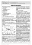
FTRFBu180.117 – Wireless room temperature sensor with clock FTRFBu180.121 – Wireless room temperature sensor with clock and backlight Function Type 010 Operating Instructions Input: R Press direct selection button and enter the ECO temperature (ECO on the display). (17 °C = factory setting) R After you confirm with , enter the time ( on the display). Enter the hour first, and then the minutes. R After you confirm with , enter the date (D on the display). Enter the year and confirm with . Then enter the month and day. R After you confirm with , enter the daily programs. To do so, first select the day of the week. A “1” for Monday will blink on the display. You select a different day of the week using and . R After you confirm the day of the week with , set the switching segments (tappets), beginning at 0:00 (midnight). Each time you press the button, a fifteen-minute tappet for comfort temperature is set. Each time you press the button, the function jumps forward one hour without setting a switching segment. Press and hold or to activate the scroll function. If you make a mistake during input, you can repeat the process and enter the values again by passing the 0:00 mark, without leaving the currently selected day. R After you confirm with , the next day of the week blinks for selection. R After you select the next day using , the copy function is enabled and the program you entered for the previous day is suggested. You can copy this program with or enter a different program. After you confirm with , the next day of the week blinks for selection, and so on. If you select Saturday, the copy function is cancelled and the Saturday program is again suggested for Sunday. For additional setting options, see Item 3, Adjustment Functions. Operating Instructions Overview 1. Notes on Operation 2. Function of Direct Selection Buttons , , , , , 2.1 Program input 2.2 Automatic , comfort and energy-saving ECO operating modes 2.3 On/off function 2.4 Holiday function 2.5 Information function 2.6 Party function 3. Adjustment Functions J.1–J.6 3.1 J.1 Registration function 3.2 J.2 Deregistration function 3.3 J.3 Display during operation – time, temperature, time/temperature alternating 3.4 J.4 Program display using switching segments (“tappet dial”) on/off 3.5 J.5 Child safety function on/off 3.6 J.6 Automatic daylight saving time adjustment on/off 4. Reset Function , 5. Battery Low Indicator 6. Lights and Display Indicators on the Wireless Room Temperature Sensor Followed by Installation Instructions 1. Notes on Operation • The direct selection buttons for on/off, holiday/party settings, operating mode switching and program input make operation simple, even if you have not used the device in a long time. • To provide a quick overview of your settings, the FTRFBu has a special information mode, also accessible via a direct selection button, in which it is not possible to change your settings unintentionally. • With the adjustment knob, which is labelled with the Celsius temperature scale, you can easily set and read the target temperature. • The times for comfort and ECO temperature are set in a familiar way that is based on mechanical time switches using switching segments (“tappets”) and continues the concept of “operating without studying”. • When you enter the values, pressing and holding the and buttons activates a scroll function. Automatic operation Holiday function Energy-saving operation Daily program Date display 2.2Automatic , comfort operating modes You use this function to switch between the three operating modes: automatic , comfort and energy-saving ECO. The operating mode that is currently set is indicated on the display by switching segments (“tappet dial”), which you may be familiar with from mechanical time switches. Visible switching segments (“tappets”) show the times for comfort mode, and missing segments indicate the times for energy-saving mode. Automatic and energy-saving modes are also indicated by the clock program symbol and the abbreviation ECO. Comfort mode is only indicated by the circular tappet dial. In the comfort operating mode , the temperature is constantly regulated to the comfort temperature that you selected with the adjustment knob. In the energysaving operating mode (ECO), the temperature is regulated to the ECO temperature that you entered. The automatic operating mode automatically switches between the comfort and energy-saving operating modes. Day of week Time display display On/off button Programming button Holiday button Info button 2.3 On/off function You use the on/off function to shut down the control completely. When you press the button, the control is switched off. If you press the button again, the device returns to the previous operating mode. To show that the control is switched off, but the batteries in the wireless room temperature sensor are not empty, “OFF” appears on the display when the control is switched off. Caution: When the control is switched off, valve and pump protection are deactivated. If valve and pump protection must remain activated, do not switch off the control. By turning the adjustment knob to the frost star, heating can be operated in frost protection mode (approximately 5 °C), and you can use the child safety function to ensure that the setting is not inadvertently changed. This way, the control is also deactivated in summer. Input buttons Party button Programming symbol Info function Party function Wireless indicator Operating mode button Child safety Time and Battery low function temperature display indicator 2.Function of Direct Selection Buttons , , , , , 2.4 Holiday function The holiday function lets you save energy when you are gone for a longer period of time and it also heats up the room to the target temperature before you return. When you press the button, the date for the following day is displayed. After you set the return date using the buttons , and , the holiday temperature appears (17 °C = factory setting). You can now change this to a setting between 5 °C and 30 °C. After you confirm the holiday temperature with , the holiday function is activated and both the return date and the holiday symbol are displayed. You can stop the holiday function at any time using the direct selection button or it will automatically end at 0:00 (midnight) of the return date that you entered. After the holiday function had ended, the control returns to the previous operating mode and the corresponding display. There are a total of six direct selection buttons which you can use to select (and exit) the desired function. While you are in a function, unneeded buttons are deactivated. To select another function, you first have to exit the currently selected function. 2.1 Program input Program input is used to set the ECO temperature, the time and date, and daily programs. While activated, it works like a compulsory guide. When you confirm a value with the button, the display switches to the next input step. While the function is active, a P appears on the display. Depending on the input step, the function of the value is also displayed using easy-to-understand symbols, and the value to be entered is blinking. When you confirm the Sunday program, the program input function closes automatically, but you can also exit it at any time using the direct selection button. If you do not press any buttons for more than two minutes, the function closes automatically. Inputs that you do not confirm with are not saved. When you finish the program input, the display returns to the previous operation screen. Last update: 05/2008 (ÄA 08/103) AR , and energy-saving ECO 2.5 Information function You can use the information function to display all settings without the possibility of accidentally changing them. While the function is active, an appears on the display. After you press the button, the set ECO temperature appears. With the and buttons, you can check the current values for all settings. It is not possible to change the values, whether intentionally or unintentionally. You 5 214 34 00 3.6 J.6 Automatic daylight saving time adjustment on/off can exit the information function at any time using the direct selection button or it will close automatically two minutes after the last button press. Selecting the information function has no effect on the control. When the information function closes, the display returns to the previous operation screen. The European Union’s standard summer time starts on the last Sunday in March at 2:00 a.m. CET and ends on the last Sunday in October at 3:00 a.m. CEST (Directive 2000/84/EC of the European Parliament and of the Council). On these dates, the wireless room temperature sensor will adjust the time automatically. For time adjustments on other dates or for regions without daylight saving time, the automatic daylight saving time adjustment can be deactivated. On (factory setting) Off 2.6 Party function The party function lets you activate a one-time comfort heating period from the moment of input, independent of the program or operating mode that is currently set. When you press the button, the next possible end time for the comfort heating period (the end of the party) appears. After you set the end time using the , and buttons, the party function is activated. The end time and the party symbol remain displayed until the end of the comfort heating period that you set. You can stop the party function at any time using the direct selection button or it will end automatically when the end time that you entered has been reached. After the party function has ended, the control returns to previous operating mode and the corresponding display. 3. Adjustment Functions J.1–J.6 4. Reset Function , The reset function returns the device to the factory state and resets all entered values for program times, ECO and holiday temperatures and adjustment settings to the factory settings. The time and date and values that were entered in technician mode are not reset. To prevent an accidental reset, this function consists of a combination of two buttons which must be pressed in the following order. Press the button first and then the button and hold it for approximately ten seconds, until the display stops blinking. Apart from the aforementioned exceptions, the factory state has now been restored. , The adjustment functions let you adjust the control to your needs and generally only need to be used once. They make it easier to use the device while in operation, and they have been removed from the normal user interface and are displayed in a special menu. To access adjustment mode, first press the button and then shortly press the button. The first adjustment function, J.1, appears on the display. Select the desired adjustment function using the , and buttons. You also make your settings using the and buttons and confirm them with . You can exit the adjustment function at any time using the button, or it will automatically close two minutes after the last button press. Inputs that are not confirmed with are not saved. Selecting the adjustment function has no effect on the control. After the adjustment function has closed, the control returns to the previous operating mode and the corresponding display. For additional setting options, see Item 12, Adjustment Functions in Technician Mode. 5. Battery Low Indicator If the blinking battery low indicator on the display is not noticed in time, the light on the wireless room temperature sensor begins to flash red for five seconds each minute. The low battery will be indicated by the light for least seven days, during which the control will continue to work. The battery low indicator does not apply to the backlight battery. After you replace the batteries, you do not have to re-register the wireless room temperature sensor. You do have to re-enter the time and date. 6.Lights and Display Indicators on the Wireless Room Temperature Sensor 3.1 J.1 Registration function Light off: The wireless room temperature sensor is functioning properly (provided that the batteries are correctly inserted). The light flashes red: The batteries are empty and must be replaced. While the light flashes, the control is still active and functioning properly. R See Item 5, Battery Low Indicator, and Item 10, Initial Operation During the registration procedure (compare 3.1 and 11), the light also flashes red. Light is continuously red: During the deregistration procedure (compare 3.2), the light is continuously red. Display indicator: Fbr Broken sensor. The device must be inspected at the factory. Display indicator: FSch 3.2 J.2 Deregistration Function Short circuit in sensor. The device must be inspected at the factory. You can use this function to deregister the wireless room temperature sensor Display indicator: This symbol appears only briefly (one second) and indicates a wireless transmis(transmitter) from a wireless heating control (receiver). After you select the button, a blinking L appears. Pressing the button again activates the ten- sion to the wireless temperature control. second deregistration procedure. During these ten seconds, the light on the wire- Display indicator: less room temperature sensor is red. To deregister the wireless room temperature The battery is empty and must be replaced. sensor, you have to press the register button on the wireless temperature control Display indicator: blinking switching segments (“heating tappets”) Blinking switching segments indicate the preferred change-over point from ECO during this time. to comfort operation during automatic mode. If the self-learning function was activated in technician mode, the preferred change-over point is determined by the 3.3 J.3 Display during operation – time, temperature, wireless room temperature sensor itself (compare Item 12.3). time/temperature alternating Display indicator: L A1 = Constant display of time (factory setting) Registration mode (see Item 3.1 and Item 11.) A2 = Constant display of temperature Display indicator: -L A3 = Display alternates between time and temperature (five seconds each) Deregistration mode (see Item 3.2) In addition to the registration procedure used for the initial operation, this registration procedure is needed to register the wireless room temperature sensor (transmitter) with multiple wireless temperature controls (receivers), without having to enter the time again by repeatedly removing the batteries. After you select the button, a blinking L appears. Pressing the button again activates ten-second registration procedure. During these 10 seconds, the light on the wireless room temperature sensor flashes red. After the registration procedure is complete, J.1 is displayed again, and you can register the wireless room temperature sensor with an additional wireless temperature control. To perform the registration procedure, follow Item 11, Registration Function, subitems 1.) and 2.). 3.4 J.4Program display using switching segments (“tappet dial”) on/off On (factory setting) Off 3.5 J.5 Child safety function on/off You can use the child safety function to prevent unintentional or unauthorised adjustments during operation. When the child safety function is active, all buttons and changes using the temperature adjustment knob will be blocked three minutes after the last button was pressed and the key symbol appears on the display. To reactivate the buttons, press and hold the button for approximately ten seconds, until the key symbol disappears. While you are pressing the button, the key symbol blinks. The buttons will again be automatically blocked three minutes after the last button is pressed. If you adjusted the target temperature on the adjustment knob while the buttons were blocked, it will apply only after the operating controls have been reactivated. On Off (factory setting) Installation Instructions After you insert the batteries, the wireless room temperature sensor first performs a self-test for a few seconds, during which all display symbols light When you insert the batteries, up. Following the self-test and subsequent display pay attention to the polarity. of the software version, the wireless room temper+ ++ ature sensor automatically switches to registration mode for two minutes, and L appears on the display. After the registration procedure (see Item 11), “00:00” blinks on the display and you are prompted to enter the time and date. If the registration proce- - dure is not performed, the device waits two minMiddle battery utes before changing to the time input screen. If for backlight the time and date are not entered, the device waits two minutes before activating the automatic operating mode . Caution: If the time and date are not entered, the time starts at 00:00 (midnight) and the comfort heating times do not correspond to the actual time of day. Item 2.1 describes how to set the time and date after automatic mode has been activated. Safety Instructions This device and a corresponding wireless temperature control (receiver) form a control unit. For this reason, the initial installation must be performed by a qualified electrical technician in accordance with applicable safety regulations. Caution: Operating near devices that do not conform to EMC guidelines can adversely affect the function of this device. Setting or changing adjustments in technician mode can affect the control’s performance and should also only be performed by a qualified technician. After installation, the installing company should instruct the user on the functions and operation of the control. The operating instructions should be stored at a location that can be easily accessed by operational and service personnel. Installation Instructions Overview 7. 8. 9. 10. 11. 12. 12.1 12.2 12.3 12.4 13. 14. 15. 16. 17. 18. Notes for the Installer Use Function Initial Operation Registration Function Adjustment Functions J.7–J.10 “Technician Mode” J.7 Unit of temperature °C/°F J.8 Valve and pump protection on/off J.9 Self-learning function on/off J.10 Adjustment (offset) of actual value measurement to room temperature ±5 K (display ±5°) Wireless Connection Function and Assignment Check Accessories Mounting Technical Data Dimensioned Drawings Warranty 11. Registration Function The registration function is used to assign a wireless room temperature sensor (transmitter) to the appropriate wireless temperature control (receiver). Before registration: A wireless room temperature sensor can be registered with a wireless temperature control in the following three scenarios: 1.) A wireless room temperature sensor has not yet been registered with the wireless temperature control. In this case, the light on the wireless temperature control is continuously red. 2.) A wireless room temperature sensor was registered with the wireless temperature control within the past hour. In this case, the light on the wireless temperature control is green, indicating a working wireless connection to this sensor. 3.) A wireless room temperature sensor was registered with the wireless temperature control more than one hour ago. In this case, the light on the wireless temperature control is off, indicating a working wireless connection to this sensor. On wireless temperature controls with output status display, the light can be either off or continuously yellow. Registration procedure: There are two ways to start the registration procedure for the wireless room temperature sensor. Immediately after inserting the batteries during initial operation, or in technician mode, as described in Item 3.1. Registration procedure after inserting the batteries: After the batteries are inserted, the self-test is complete, and the software version is displayed, an L indicating registration mode blinks for two minutes. The wireless temperature control now switches to registration mode. Briefly press the button on the wireless room temperature sensor. The wireless room temperature sensor transmits the registration code for ten seconds, and then switches to the time entry screen. 1.) Switch the wireless temperature sensor to registration mode and briefly press the register button on the wireless room temperature control. R The light on the wireless temperature control flashes red for a maximum of 30 seconds. If no transmitter is registered during this time, the light stops flashing and returns to its initial state. 2.) Briefly press the button on the wireless temperature sensor. R The light on the wireless room temperature sensor flashes red for approximately ten seconds and the light on the wireless temperature control changes from flashing red to continuously green. The wireless connection is established. After being registered correctly, the light on the wireless temperature control is green for approximately one hour – the control is now active. For other indicators on the wireless temperature control, see the “Indicator Lights” Item in the operating instructions. After placing the wireless room temperature sensor in the room you want to regulate, you should again check for the continuous green light on the wireless temperature control to make sure that the wireless connection is working. If the wireless connection has been interrupted, the light will turn red after approximately three minutes. One hour after registration, the green light goes out, indicating normal operation. 7. Notes for the Installer You can find descriptions of the following functions in the operating instructions for the wireless temperature control. R Average-value control (temperature measurement from multiple wireless room temperature sensors) R Master-slave control (automatic operation for multiple rooms via central wireless room temperature sensor with clock) R Loss of connection (interruption of wireless connection) R Failsafe operation when connection is lost (control when wireless connection is interrupted) 8. Use This wireless room temperature sensor (transmitter) with its time-controlled energy-saving function was specially designed for temperature measurement in residential, office and hotel rooms and is operated together with one or more wireless temperature controls (receivers). The complete unit of a wireless room temperature sensor and a wireless temperature control functions as an individualroom temperature control. The wireless room temperature control is mainly used in renovations, for extensions to heating systems in order to avoid extensive work tearing up walls and re-plastering for laying electrical cables, or in modern office complexes, where flexibility in room design is a priority. For uses that were not anticipated by the manufacturer, follow applicable safety regulations. With regard to suitability for unanticipated uses, see Item 18, Warranty. 9. Function The FTRFBu measures the room temperature using an internal sensor and transmits this value and the desired target temperature to the registered wireless temperature control. You can register any number of wireless room temperature sensors (transmitters) with any number of wireless heating controls (receivers). In this way, you can use one sensor to control multiple electric heaters/heating plates or warm-water valves. The transmission range of the wireless room temperature sensor is largely dependent upon the room conditions. Reinforced walls and ceilings and metal casings reduce the effective range. 10. Initial Operation 12.Adjustment Functions J.7–J 10 “Technician Mode” J.6 R then and Depending on the device type or packaging size, the device is delivered either in a closed state or already opened for faster mounting. When delivered, the wireless room temperature sensor is not yet ready for use. To prepare it for use, first insert the batteries and register the wireless room temperature sensor (transmitter) with the wireless temperature control (receiver) (see Item 11, Registration Function). When you insert the batteries, pay attention to the polarity (+/–). To ensure maximum operational duration, only use new batteries of the same, type, size and quality as the original batteries. The FTRFBu180.121 can be operated with a third battery for the backlight. This battery is inserted between the two batteries needed for the temperature control. The battery life expectancy of the two batteries required for the temperature control is thereby independent of the backlight. Caution: The adjustment functions are used to make control settings and may only be performed by a qualified heating/electrical technician. The settings in technician mode must be made intentionally and they cannot be cleared using the reset function. This provides clear proof that the settings were made by a person. Technician mode is activated from normal adjustment mode (Item 3). Here, J.6 must appear on the display. Press the button first and then briefly press the button – the display shows the first adjustment function in technician mode, J.7. After you activate technician mode, you can select all 10 adjustment functions using the and buttons. You can leave technician mode at any time using the button. Otherwise, it will automatically close two minutes after the last button press. Inputs that are not confirmed with are not saved. When you exit technician mode, the display returns to the previous operation screen. 15. Mounting 12.1 J.7 Unit of temperature °C/°F Switching the unit of temperature is indicated directly by °C or °F (factory setting = °C). The FTRFBu is best mounted using double-sided tape or (on wallpapered walls) common screws directly on an inner wall, opposite the heating device at a height of 1.50 m. The mounting surface must be dry, free of dust and grease, flat, and stable. Mounting on tables, shelves and cabinets is not recommended, due to unfavourable air currents and influences from external heating sources (e.g. people, equipment, candles, sunlight, etc). An adhesive strip is included with the product. Accessory part JZ-18 can be used as a wall bracket. To open or close the device, consult the following diagrams. 12.2 J.8 Valve and pump protection on/off The valve and pump protection helps prevent the valve seat and/or pump from failing due to corrosion when they are not used for a long period of time. We recommend activating valve protection for warm-water heaters. The wireless room temperature sensor transmits the signal to the wireless temperature control on Monday from 11:00 to 12:00. During this time, the wireless temperature control activates the valve and pump once for five minutes. Valve and pump protection is only activated if heating has not been used during the past week. Unneeded heating up during the heating season is thereby avoided and the control is not affected. On Off (factory setting) 12.3 J.9 Self-learning function on/off The self-learning function independently reaches the comfort temperature at a set point in time. The preferred change-over point from ECO to comfort temperatures is adjusted automatically and is indicated by blinking switching segments (“heating tappets”). The heating-up time varies according to heating output and outside temperature. On (factory setting) Off 12.4J.10 Adjustment (offset) of actual value measurement to room temperature ±5 K (display ±5°) 16. Technical Data Power supply: Battery life: Battery 2u or 3u AAA. Do not use rechargeable batteries. More than two years. Frequent use of buttons reduces the battery life for the backlight. Caution: Replace the batteries at least once every five years. Temperature sensor: Internal Adjustment range: 5 to 30 °C Resolution: 0.1 K Sensor tolerance: Approximately ±1 K Adjustment scale: Celsius temperature scale Transmitting frequency: 868.3 MHz Permissible ambient temperature: 0 to 50 °C Permissible ambient temperature: –20 to +70 °C Permissible humidity: Max. 95% RH, not condensing Casing: Berlin 3000 Casing material and colour: ABS plastic, pure white (similar to RAL9010) Protection class: III Protection type: IP20 Mounting type: Wall-mounting using screws, adhesive strips or wall bracket You use the offset to adjust the actual value measurement to the room temperature (goal: target value scale/actual value display = room temperature). This adjustment is needed when a constant thermal influence from an external heating/cooling source acts on the wireless room temperature sensor and cannot be avoided. If the wireless room temperature sensor is affected by an external heating source, for example, a cooler room temperature will be set than the one selected with the target value knob. The offset of the actual value measurement can be made in increments of 0.1 K. External heating source example: Situation: When you set the target temperature to 22 °C, the room temperature is 20 °C. To achieve a room temperature of 22 °C, while leaving the target value setting at 22 °C, the difference of 2 K must be subtracted from the actual value measurement using the offset. R Offset value –2.0°. The wireless room temperature sensor adjusts the measured actual value by –2 K, which raises the room temperature to 22 °C. R Target value scale/actual value display = room temperature. External cooling source example: Situation: When you set the target temperature to 22 °C, the room temperature is 24 °C. To achieve a room temperature of 22 °C, while leaving the target value setting at 22 °C, the difference of 2 K must be added to the actual value measurement using the offset. R Offset value +2.0°. The wireless room temperature sensor adjusts the measured actual value by +2 K, which lowers the room temperature to 22 °C R Target value scale/actual value display = room temperature. 17. Dimensioned Drawing 13. W ireless Connection Function and Assignment Check You can use this function to check whether wireless room temperature sensors are correctly assigned to various wireless heating controls. This makes it easy to find mistakes later on. R Activate the registration procedure on the wireless room temperature sensor (transmitter). R During this time, the light on the wireless room temperature sensor flashes red. If the light on the wireless heating control (receiver) starts to flash green, the wireless room temperature sensor is registered with it and the wireless connection is established. 14. Accessories JZ-18 – Adapter plate as a wall bracket (Berlin 3000 Funk) 18. Warranty The technical data cited here was determined in laboratory conditions according to generally applicable test specifications and DIN regulations, in particular. Characteristics can only be assured to this extent. Checking the suitability of the intended use or operation under the terms of use is the responsibility of the buyer and as such is not covered by the warranty. Subject to change. ALRE-IT Regeltechnik GmbH • Richard-Tauber-Damm 10 • 12277 Berlin, Germany Phone: +49(0)30/399 84-0 • Fax: +49(0)30/391 70 05 • [email protected] • www.alre.de