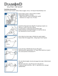
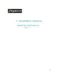
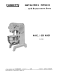
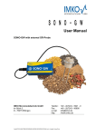
1
Operating Instructions
Change the position of selector switch 2 to
and then, using handles A, remove the
mobile part.
Bring it up against to be butted against the
ERT.
Change the position of selector switch 2
back to
.
Note: moving the circuit-breaker on the ERT
must be done near the ground.
Disconnect the ERT by turning the 2
notching operating mechanism handles
towards the left then pulling them.
Unblock the ERT castors.
Remove the ERT then place the mobile part
on the ground by activating the handle.
Remove the ERT.
Before closing the access door to the mobile
part, pull down the panel.
Close the access door to the mobile part
by turning the handle towards the left, then
pushing it.
07897302EN indice : C0
21
Operating Instructions
insertion
Open the access door to the mobile part by
pulling then turning the handle towards the
right.
Bring the ERT into position. (the pins
entered into the holes intended for this on
the cubicle).
Block the 2 ERT castors.
Lock the latching mechanism by pushing
in, then turning towards the right the
2 ERT notching operating mechanism
handles (check latching mechanism).
Change the position of selector
switch 2 to
.
Push the mobile part into the cubicle until
butted against it then change the position of
selector switch 2 back to
.
Disconnect the ERT by turning then pulling
the 2 notching operating mechanism
handles to the left.
Unblock the 2 ERT castors and remove it.
22
Plug in the LV socket, to do so, push and
keep pressing the red button located under
the lock pressed down.
Push the lock.
Connect the cord and notch it.
07897302EN indice : C0
Operating Instructions
Before closing the access door to the mobile
part, lift the panel, and ensure that it is well
notched at the top.
07897302EN indice : C0
Close the access door to the mobile part by
turning the handle to the left then pushing it.
23
Operating Instructions
Plugging in the mobile part
Starting status
Door closed
Selector switch 4 to
(open earthing switch)
Selector switch H in plug-in or drawout
position to
Operation
Lower the protective flap of push-button 1.
Press push-button 1, and while keeping it
pushed down.
Change the position of selector switch 2
to .
Insert the crank into opening 3.
Plug in the mobile part by turning the crank
(45 turns) clockwise until the position
indicator changes status.
Change the position of selector switch 2
to
.
In the case of a circuit-breaker or a
contactor, the electric operation for charging
the downstream part of installation is now
possible.
The pictogram with a black background
on the front plate is a reminder of the
operations.
24
07897302EN indice : C0
Operating Instructions
Withdrawing the mobile
part
The mobile part in the plugged-in position.
Starting status
Operation
Press push-button 1 (which sends an order
for the mechanical opening of the circuitbreaker).
While keeping it pushed down, change the
position of selector switch 2 to
.
Insert the crank into opening 3.
Withdraw the mobile part by turning the
crank (45 turns) anti-clockwise until the
position indicator changes status.
Change the position of selector switch 2
to
.
The mobile part is withdrawn.
The cubicle is in the disconnected position.
The pictogram with a black background
on the front plate is a reminder of the
operations.
07897302EN indice : C0
25
Operating Instructions
Closing the earthing switch
Starting status
The mobile part is in a disconnected position
or in an extracted position, that is, absent
from the cubicle.
Check that the voltage presence lights
are not lit.
Any potential locks must enable the
operation to be carried out.
Operation
Change the position of selectorswitch 4
to
, by pulling it and turning it
towards the right.
Insert the crank into the pin of operating
axis 5, and turn it clockwise until the position
indicator changes status.
Closing is accompanied by a noise
(sudden closing).
26
07897302EN indice : C0
Operating Instructions
Change the position of selector switch 4
to , by pulling it and turning it towards the
right.
The earthing switch is in the closed position.
The MV cable heads are short-circuited and
earthed.
The pictogram with a yellow background
on the front plate, is a reminder of the
operations.
07897302EN indice : C0
27
Operating Instructions
Opening the earthing
switch
Closed earthing switch
Any potential locks must enable the
operation to be carried out.
Starting status
Operation
Change the position of selector switch 4
to
, by pulling it and turning it
towards the left.
Insert the crank into operating axis 5, and
turn it anti-clockwise until the position
indicator changes status.
The change of status is accompanied by a
sudden closing noise.
Change the position of selector
switch 4 to
by pulling it and turning
it towards the left.
28
07897302EN indice : C0
Operating Instructions
The earthing switch is in the open position.
The pictogram with a yellow background
on the front plate, is a reminder of the
operations.
07897302EN indice : C0
29
Operating Instructions
Plugging in VT fuses
Starting status
Assembled lower panel
Selector switch 6 to
Operation
Change the position of selector switch 6
to
, by pulling it and turning it
towards the right.
Insert the crank into operating axis 7, and
turn it clockwise until it is plugged in.
Plug-in is completed when resistance can be
felt (stop).
Change the position of selector switch 6
to
, by pulling it and turning it towards
the right.
The pictogram with a blue background
on the front plate, is a reminder of the
operations.
30
07897302EN indice : C0
Operating Instructions
Withdrawing VT fuses
Starting status
Assembled lower pane
Selector switch 6 to
Operation
Change the position of selector switch 6
to
, by pulling it and turning it
towards the left.
Insert the crank into operating axis 7, and
turn it anti-clockwise until drawout.
Change the position of selector switch 6
to
, by pulling it and turning it
towards the left (this authorises the removal
of the fuse access panel).
The pictogram on the front panel, is a
reminder of the operations.
07897302EN indice : C0
31
Operating Instructions
Padlocking and preventing
access using padlocks
Number of possible padlocks per
cubicle type
3 padlocks on the plug-in prevention selector
switch.
3 padlocks on the selector switch of plug-in
or drawout VT fuses.
Nota : used padlocks Ø 6 to 8 mm.
1 padlock on the protective flap of the
mechanical opening push-button of the
mobile part.
1 padlock on the operating mechanism of
each of the plug-in contact flaps
3 padlocks on the earthing selector switch in
the opened or closed position.
Preventing the plug-in
of a mobile part
Place 1 to 3 padlocks on the plug-in
prevention selector switch H.
Plug-in prevention in
Preventing the opening of
a compartment flap on the
withdrawable part (option)
Close with padlock
On the operating mechanism of the plug-in
contact flaps, when they are closed.
The flap operating mechanism is located
inside the cubicle, on the right side.
Press on the flap guide, and place the slides
(1 and 2, 1 or 2) then place the padlocks in
the holes.
40 kA/1s internal arc withstand:
to get to the shutters mechanism,
you must remove the metal sheet closing
(2 screws A).
The metal sheet must be installed before
to insert the circuit-breaker.
32
07897302EN indice : C0
Operating Instructions
Preventing the mechanical
opening order of a withdrawable
part in an operational position
Place 1 padlock on the mechanical opening
push-button protective flap 1.
Can also serve as an additional plug-in and
drawout lock out.
Padlocking the earthing switch
Open earthing switch:
place 1 to 3 padlocks on selector switch 4 to
prevent closure.
Closed earthing switch:
place 1 to 3 padlocks on selector switch 4 to
prevent opening.
This also prevents the plug-in of a mobile
part.
plugged-in fuses:place 1 to 3 padlocks on
selector switch 6 to prevent drawout.
This also prevents removalof the front panel.
Withdrawn fuses:place 1 to 3 padlocks on
selector switch 6 to prevent plug-in.
Padlocking the operation of VT
fuses
07897302EN indice : C0
33
Operating Instructions
Locking using locks
(option)
Mobile part in a drawn out position:
1 lock on the cubicle (2 O) or (2 C) or (1
O and 1 C) or (1 O) or (1 C): on earthing
switch.
Disconnector carriage (withdrawable busbar
bridges):
1 lock in the plugged-in position (on the
disconnector).
Number of possible locks
Locking on a cubicle
The wrench is only released when plug-in
prevention is locked.
Locking the plug-in prevention of a mobile
part.
Locking the disconnector
carriage in the plug-in position
The wrench is only released when the
mobile part is in the plug-in and locked
position.
Closed disconnector
Plugged in disconnector carriage
Locking the earthing switchwith
a lock
1 lock in closed position
Locking the earthing switchwith
two locks
34
1 lock in open position
(2 O) or (2 F) or (1 O et 1 F) or (1 O)
or (1 F).
07897302EN indice : C0
Operating Instructions
Locking using an
electromagnet (option)
Locking the earthing switch
The electromagnet automatically locks
the earthing switch in the “open” and
“closed” position.
A push-button located on the low voltage
compartment authorises the operation
of selector switch 4, if switchboard
configuration is certain.
Locking on a cubicle
The electromagnet automatically locks
plug-in padlocking when it is activated.
Electromagnetic locking prevents the plug-in
of a mobile part.
A push-button located on the low voltage
compartment authorises unlocking,
if switchboard configuration is certain.
07897302EN indice : C0
35
Corrective maintenance
Forward
Corrective maintenance operations allow for
defective subassemblies to be replaced.
For any other intervention,call upon the
nearest Schneider group agents.
The operations mentioned in the summary
table here after can be carried out by the
customeror by Schneider Electric After Sales
agents.
After each operation, carry out electric
tests in compliance with the standards
in force.
Careful: during replacement, all the
following accessories must absolutely
be replaced by new equipment.
- Nylstop (self-locking nut)
- Contact washer
- Stop rings
- Mechanical pin.
Summary table
Description
Execution
Comments
Replacement on FU (cubicle AD or CL)
Busbar rating
Earthing switch clamps and capacitive isolators
For any intervention,
Plug-in pins
call the nearest
Upper and lower bushing
Schneider Electric
Increase in the number of cables
agents.
Flaps and flap operating mechanisms
Extraction of a cubicle
VT fuse
Customer/
See the following page
VPIS voltage indicator box
Customer/
See the following page
CT
Customer/
See Kit no. 07897207 instructions
Anti-condensation resistor
Customer/
Consult us
Earthing switch position auxiliary contact block
Customer/
See Kit no. 07897324 instructions
Surge arrester
Customer/
Consult us
Locking using plug-in padlocking lock(s)
Customer/
See Kit no. 07897330 instructions
Plug-in padlocking electromagnetic locking
Customer/
See Kit no. 07897326 instructions
Locking using earthing switch lock(1)
Customer/
See Kit no. 07897328 instructions
Locking using earthing switch locks(2)
Customer/
See Kit no. 07897329 instructions
Earthing switch electromagnetic lockin
Customer/
See Kit no. 07897325 instructions
Locking using lock(s) for prevention of withdrawal
Customer/
Consult us
Zero frequence toroid
Customer/
See Kit no. 07897216 instructions
VT and VT compartment
Customer/
See Kit no. 07897218 instructions
High voltage contacts on VT fuses
Customer/
See Kit no. 07897219 instructions
MV handles
Customer/
See Kit no. 07897220 instructions
Cable connection bar support isolators
Customer/
Consult us
Circuit-breaker carriage position auxiliary contacts
Customer/
See Kit no. 07897222 instructions
Withdrawable VT auxiliary contacts
Customer/
Consult us
Withdrawable VT fuse blowing auxiliary contacts
Customer/
See Kit no. 07897223 instructions
Printed circuit and relay support (STPI)
Replacing the fans on 3600 A / 4000 A cubicles
Cleaning ventilation grids on 3600 A / 4000 A cubicles
Customer/
Customer/
Customer/
Consult us
See page 41
See page 17
36
07897302EN indice : C0
Corrective maintenance
Replacement of VT
compartment fuses
Starting position
Withdrawn fuses and disconnected VT low
voltage connector (see chapter “Operating
instructions”).
Remove the protective panel (see chapter
“Instructions for access to the inside of a
cubicle”).
Removing
1:
2:
3:
4:
raise vane A
disconnect the small vertical rod B
pivot the striker pads C into a horizontal position
carefully remove the pin from the striker pads D.
D
07897302EN indice : C0
37
Corrective maintenance
5: push wrench E and turn towards the left and let go. The fuse is unlocked.
6: Remove the wrench and the fuse.
Placing
Place the spring on the wrench and check
that it is butted against the bottom of the
wrench and positioned between the two clips
indicated by the arrows.
Place the fuses, with the strikers on the
outside.
Fit the wrenches on the fuses (spring
towards the bottom).
1: push wrench E
2: turn it towards the right and let go.
The fuse is locked, check the wrench latching mechanism.
38
07897302EN indice : C0
Corrective maintenance
3: carefully insert the pin on the striker pads D.
4: raise vane A to place the striker pads C in a vertical position.
5: connect the small vertical rod B to ensure free operation of the small rod.
Operation
07897302EN indice : C0
D
Connect the VT low voltage connector (see
chapter “Operating instructions”).
Place protective panel (see chapter
“Instructions for access to the inside of a
cubicle”).
39
Corrective maintenance
Replacing of a voltage
indicator box
Removing
This operation can be carried out while
the equipment is energised.
Placing
Remove the 2 fastening screws (A) from the
voltage indicator box.
Remove the voltage indicator box (B) and
disconnect the connector.
Check on the characteristics label (B)
that the new box corresponds to the rated
voltage of your network.
Place the new voltage indicator box in the
reverse order of removal.
- 1.7 kV to 3 kV
- 3 kV to 7.2 kV
- 10 kV to 24 kV.
40
Tightening torque: 0.1 mdaN.
07897302EN indice : C0
Corrective maintenance
Replacing the fans on
3600 A / 4000 A cubicles
With or without capacitor
Removing withpower off.
1: disassemble the 10 screws (A) take off
the cover.
3: disassemble the 8 screws (C) securing
the fan to the cover of compartment (A).
2: disconnect the wires (D) mark the wires
when disassembling.
Replacing the capacitor
With power off.
Remove the roof plate on each cubicle
(6 screws).
07897302EN indice : C0
To acc the capacitor.
41
Corrective maintenance
Mark the wiring and disconnect (A).
Putting back the new
capacitor
Disassemble the nut and washer (B).
Fit the fan and the capacitor (if necessary) in the opposite order to disassembly.
Check on the characteristics label that
the new fan and capacitor match the
rated voltage indicated.
- 5 1237 333FA 220 Vac
- 5 1237 333FB 110 Vac
- 5 1237 333FC 48 VD.
42
07897302EN indice : C0
07897302EN indice : C0
43
44
07897302EN indice : C0