1
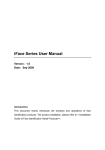
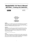
T-7 FINGERPRINT TERMINAL
HARDWARE USER'S MANUAL
Rev 1.1
1
Table of Contents
1. INTRODUCTION
1.1 SUPPLIED PART LIST
1.2 ABOUT PEGASUS T-7
1.3 HARDWARE SPECIFICATION
2. PRODUCT OVERVIEW
2.1 COMMUNICATION
2.2 POWER MANAGEMENT
2.3 KEYPAD FUNCTIONS
2.4 USER MANAGEMENT
2.5 USER ENROLLMENT
2.6 HARDWARE DESCRIPTION
3. BASIC SETTINGS
3.1 SYSTEM SETTINGS
3.1.1 TOTAL NUMBER OF ADMINISTRATORS
3.1.2 MACHINE NUMBER
3.1.3 BAUD RATE
3.1.4 LANGUAGE
3.1.5 AUTO POWER OFF
3.1.6 VOICE INDICATION
3.1.7 RESTORE FACTORY DEFAULT
3.2 EVENT SETTINGS
3.2.1 ADMINISTRATIVE EVENT FULL WARNING
3.2.2 ATTENDANCE EVENT FULL WARNING
3.2.3 VAID ATTENDANCE TIME INTERVAL
3.3 MENU HIERARCHY
3.3.1 FIRST LEVEL MENU ITEMS
3.3.2 SECOND LEVEL MENU ITEMS
3.3.3 “SETTING” CONFIGURES THE MAJOR FUNCTION OF T-7
3.4 MACHINE OPERATION FOR ADMINISTRATOR
3.4.1 TO SHOW THE FIRST LEVEL MENU
3.4.2 MACHINE MANAGERMENT
3.4.3 PASSWORD REGISTRATION
3.4.4 ID CARD REGISTRATION
(OPTIONAL FUNCTION FOR SPECIAL MODEL)
3.4.5 DELETE USER
2
3.5 ATTENDANCE LOG AND SYSTEM LOG MANAGEMENT
3.5.1 QUERY ATTENDANCE LOG
3.5.2 QUERY THE SYSTEM LOG
3.5.3 DELETE ALL RECORD
3.5.4 SETTINGS
3.5.5 MACHINE ID
3.5.6 MANAGERS
3.5.7 LANGUAGE
3.5.8 VOICE INDICATION
3.5.9 LCD CONTRAST
3.5.10 AUTO POWER OFF
3.5.11 RELAY OUTPUT SIGNAL (NOT FOR X628U)
3.5.12 RESTORE FACTORY SETTING
3.5.13 LOG MANAGEMENT
3.5.14 SYSTEM LOG WARNING
3.5.15 ATTENDANCE LOG WARNING
3.5.16 REVERIFY
3.5.17 LOG QUERY
3.5.18 ENROLL INFO
4. QUICK SETUP GUIDE
4.1 HARDWARE
4.1.1 POWER ON/OFF T-7
4.1.2 COMPUTER CONNECTION
A. THROUGH RS232
B. THROUGH RS485
C. THROUGH TCP/IP
4.2 SOFTWARE
4.2.1 PACKING LIST
4.2.2 FINGERPRINT REGISTRATION
4.2.3 SOFTWARE INSTALLATION
3
CHAPTER ONE
INTRODUCTION
4
1.1 SUPPLIED PART LIST
1.
2.
3.
4.
T-7 Fingerprint Terminal
9V/1A Power Supply
RS232 Cable (1m)
Pegasus 5.0Attendance Management CD
1pcs
1pcs
1pcs
1pcs
1.2 ABOUT PEGASUS T-7
The Pegasus T-7 is a flexible and reliable design to meet the market requirement for a
robust and secure biometric Time & Attendance solution at a reasonable cost. T-7 allows
you to register up to 2,000 fingerprints and store up to 50,000 transactions.
1.3 HARDWARE SPECIFICATION
Fingerprint Template Capacity
2,000
Transaction Capacity
50,000
Verification Mode
1:1 or 1:N
Communication
RS232/RS485(up to 32 channels)
TCP/IP
Keyboard and Display
128x64 LCD with blue back light and 16key keypad
Power Supply
9 VDC, standby current: 2.5A, operating
current: 400mA
Identification speed
< =2 seconds
FRR (False Rejection Ratio)
< =0.01%
FAR (False Acceptance Ratio)
< =0.0001%
Operating Environment
Temperature: 0°C – 45°C
Humidity: 20% – 80%
Language Support
English
Dimension
189(L)*137(W)*50(H)mm
5
CHAPTER TWO
PRODUCT OVERVIEW
6
2.1 COMMUNICATION
Pegasus T-7 Provides RS232, RS485 and TCP/IP communication interfaces and depicted
below:
RS232
RS485
TCP/IP
2.2 POWER MANAGEMENT
When T-7 is in power down mode, the device is brought into operational mode once Power
Key is pressed and ready for clocking.
When the device is in operational mode, the device is brought into power down mode once
Power Key is pressed and held for 4 seconds.
If the automatic power down has been set, the device will be brought into power down
mode according to defined time schedule.
2.3 KEYPAD FUNCTIONS
ESC
MENU
OK
?
?
0...9
?
1
4
7
2
5
8
3
6
9
?
0
OK
ESC
MENU
?
?
Move one level up from the menu hierarchy
Get into the system setting menu
Confirm the current setting
Move the cursor up
Move the cursor down
Numeric keys
Power ON/OFF switch
7
2.4 USER MANAGEMENT
Two User roles are defined in T-7, namely manager or normal user.
− Normal users can clock on the device but can NOT access the settings.
− Managers can clock on the device as well as do system management:
1. Register/delete normal users' fingerprints and passwor ds.
2. Browser attendance records as well as other system information.
3. Set up system configurations
2.5 USER ENROLLMENT
Enrollment is the process of creating an ID, assigning a password (optional) and scanning a
user’s fingers to create the fingerpr int templates. All these associated information are stored
in the device.
During user verification, the stored fingerprint templates are compared to the current
scanned fingerprint to confirm the user’s identity.
Enrollment takes approximately 2 seconds for each user. Up to 3 fingers can be enrolled for
the same ID number. Ideally, at least one finger on each hand should be enrolled in case of
injures.
8
2.6 Hardware Description
LCD Display
Show the Current Date & Time
Attendance Information
LED Indicator
Indicate the Power Status
And Operation Status
ESC Key
Cannel or return to upper
menu the menu up
Menu Key
Show the operation menu
up
Number Key
Input Number and
choose items in menu
Fingerprint Scanner
The Fingerprint scanning
area
Power Key
Power On or Power
Off the machine
? ? Key
Scrolling the menu
OK Key
Confirm the operation
9
CHAPTER THREE
BASIC SETTINGS
10
3.1 SYSTEM SETTINGS
3.1.1
Total Number of Administrators
Setting
Description
1 -10
set total number of administrators in T-7
Factory Default
5
3.1.2 Machine Number
Setting
Description
1 -255
set an unique address ID to T-7 to network with multiple
machines
Factory Default
1
3.1.3
Baud Rate
Setting
Description
9600
set the communication speed to 9,600 bps (Bit Per
Second)
19200
set the communication speed to 19,200 bps
38400
set the communication speed to 38,400 bps
Factory Default
38400
* S peed setting should be the same with PC, otherwise communication shall fail.
3.1.4
Language
Setting
Description
English
set all display information in English
Traditional
Chinese
Set all display information in Traditional Chinese
Factory Default
English
3.1.5
Auto Power Off
Setting
Description
NO
auto power off function is disabled
1 - 255
Auto power off when there are no activities on the
device. The unit is in minute.
Factory Default
NO
11
3.1.6 Voice Indication
Setting
Description
YES
Activate the voice indication
NO
Inactivate the voice indication
Factory Default
YES
3.1.7 Restore Factory Default
If OK key is pressed, all the current setting will lose and restore to the factory default
settings.
12
3.2 EVENT SETTINGS
3.2.1
Admin istrative Event Full Warning
The machine will give a “FULL” warning signal when the administrative event buffer is
below the set threshold.
Setting
Description
NO
There's no warning if there's no administrative event
buffer left, and no further administrative events will be
logged.
1 - 255
Factory Default
100
3.2.2 Attendance Event Full Warning
The machine will give a “FULL” warning signal when the attendance event buffer is
below the set threshold.
Setting
Description
NO
There's no warning if there's no attendance event buffer
left, and no further attendance events will be logged.
1 - 1500
Factory Default
3.2.3
1000
Valid Attendance Time Interval
If this time interval is set, only ONE attendance event will be logged if there are multiple
attendance events within this time interval for the same user.
Setting
Description
NO
All attendance events will be counted as valid one.
1 - 255
Factory Default
NO
13
3.3
MENU HIERARCHY
There are three kinds of menus:
1. Operation Menu
2. Setting Menu
3. Status Menu
3.3.1 First Level Menu Items
The first level menu items show up when MENU key is pressed if
there’s no available administrators, affirmation will be done otherwise.
MENU
1. Enroll
2. Delete
3. Download
4. Time Set
5. Settings
6. Info View
14
3.3.2 Second Level Menu Items
User Registration Management
The Item “Enroll” includes 4 Sub Items which are “User Enroll”, “Manager Enroll”,
“Sec Level Set” and “ USB Upload”
The Sub Items will show up after user select “Enroll” ,which under the first level
menu, and Press “OK”.
Enroll
1. User Enroll
2. Manager Enroll
3. Sec Level Set
4. USB Upload
Select the level of user registration (User Enroll / Manager Enroll) and Press “OK”.
The Third Level Menu Items show up as the figure below. “New Enroll” is for new
user registration. “Backup Enroll” is for enrolling *“Backup Record” of registered
user.
User Enroll / Manager Enroll
1. New Enroll
2. Backup Enroll
(*p.s.: “Backup Record” means the 2nd or 3rd Finger Print template, Password and ID card”.
15
The registration method shows up after “New Enroll” or “Backup Enroll” is selected.
New Enroll / Backup Enroll
1. Finger
2. Password
3. Card
“Sec Level Set”
There are 2 options under “Sec Level Set” which are “1:1 Verify” and “1:N Identify”.
“1:1 Verify” - Compare the user ’s fingerprint and the fingerprint template stored in
card. (Optional Setting depends on the model)
“1:N Identify” – Compare the user ’s fingerprint with the fingerprint template of all
registered user stored in machine.
Sec Level Set
1. 1:1 Verify
2. 1:N Identify
”USB Upload”
The Backup of Menu Setting can be uploaded from USB storage device to the FringerPrint
Machine. (Optional Setting depends on the model)
16
Delete User
The “Delete Menu” shows up after select “Delete ” under the First Level Menu and pressed
“OK”. Enter the UserID by number or direction key. Press “OK” to confirm the deletion.
Delete
ID
ESC
00001
ENTER
Data Download
The Sub Items show up after select “Download” user First Level Menu.
Download
1. USB Download
2. RS232 Set
3. RS485 Use
4. Etnernet Set
USB Download
There are two options under the “USB Download”, which are “GLog” and “Enroll
Data”.(Optional Function depends on the model)
“Glog”
Attendance Record Download
“Enroll Data”
Fingerprint Template Download
17
Time Setting
The Time Setting Menu shows up after select “Time Set” under the First Level Menu and
pressed “OK”.
Date & Time
2007-03-14
14:22:25
WED
Move the cursor location by direction key. Enter the correct value by number key.
(The weekday value is generated by machine automatically).
18
3.3.3 “Setting” configure s the major function of T-7.
There are two items under “Setting”, which are “Terminal” and “Log”.
Settings
1. Terminal
2. Log
“Terminal” configures the settings of machine operation.
“Log” configures the settin gs of data logging
The sub items are shown below.
Terminal Set
1. Machine ID
2. Managers
3. Language
4. Voice Out
5. LCD Con
6. Auto Off
7. Lock Ctrl
8. Restore Def
19
Log Set
1. SLog Wrn
2. GLog Wrn
3. Reverify
Machine ID: The Unique ID of the machine on the same communication channel.
Managers:
The maximum number of machine administrator.
Language:
The language of operation menu. T-7 supports 2 language s which are Traditional
Chinese and English.
Voice Out:
Enable or disable the function of voice indication.
LCD Con:
The contrast of between the display and back-light.
Auto Off:
The machine will shut down after a certain idle time. (The function is disable on the
default setting) .
Lock Ctrl:
The duration of Open door signal.
Restore Def:
Restore all settings which under “Settings” to factory default setting.
Slog Wrn:
To set the limit of residue system log memory. If the number of residue system log
memory reach the limit. Warning occurred. (All administrators’ operation is record as system log.)
Glog Wrn:
To set the limit of residue attendance record memory. If the number of residue
attendance record memory reach the limit. Warning occurred.
Reverify:
The duration of 2 successful attendances which from the same fingerprint. All
duplicate attendance record does n’t be recorded.
Detail Information
“Info View” shows the registration code, records, manufacturer and firmware version.
The sub items are shown below.
20
Info View
1. Enroll Info
2. Log Info
3. Sys Info
Enroll Info: To show the information about user registration such as the number of registered
user, number of registered administrator, number of fingerprint template, number of registered
password and number of registered ID Card.
Log Info
To show or operate the machine record such as number of attendance record,
number of system log, attendance record of user, system log of administrator, and delete all record.
Sys Info:
To show hardware information which includes Manufacturer, Machine Name,
Release Date,. Serial Number, Engine Version and Soft Version.
21
3.4 Machine Operation for administrator
3.4.1 To show the First Level Menu
Without registered
Administrator
Press Finger...
16:21:34
MENU
1 .Enroll
2 .Delete
3 .Downlo ad
FingerPrint
Verificatio n
Press "Menu"
2 007 -03 -18 SUN
With registered
Adminis trator
MENU
1 .Enro ll
2 .Delete
3 .Download
Manager Co nfirm
Menu Lo gin ...
Enter Administrato r ID
i.e. "4"
EnterPass word
and Press "OK"
1 :1 FP Verify
Press "OK"
ID
ESC
0 000 4
ENTER-Pwd
PWD Verify
ID
00 004
PWD
ESC
ENTER-Verify
If the “manager confirm” is requested on the operation and the user didn’t enroll any administrator,
please shut down the machine and contact with retailer.
If confirmation is fail, “Illegal” is shown and request the reconfirmation.
FP Identify
Take Off ...
Illegal!
FP Identify
Again Press ...
22
3.4.2 Machine Management
New User Registration / New Administrator Registration
Step 1 Enter the First Level Menu (Refer to Page.)
Step 2 Press “1” to choose “Enroll”
MENU
1.Enroll
2.Delete
3.Download
Step 3 Press “1” to choose “User Enroll” for normal user registration
Or
Press”2” to choose “Manager Enroll” for administrator registration
Level Selection
1.User Enroll
2.Manager Enroll
3.Sec Level Set
Step 4 Press “1” to choose “New Enroll”
Enroll Method
1.New Enroll
2.Backup Enroll
Step 5 Press “1” to choose “Finger” for Fingerprint Enrolling.
Enroll Object
1.Finger
2.Password
3.Card
Step 6 Enter the User ID (i.e) 00001 and Press “OK”.
New FP
ID
ESC
00001
ENTER
Step 7.Show you finger on the window
Press Finger!
First
23
Step 8.Show you finger on the window again
Press Finger!
Second
Step 9.Show you finger on the window again
Press Finger!
Third
Successful Registration
Step 10 Press ”ESC’ to quit the registration process.
New FP
ESC
More New?
ENTER
Enrolled User Registration (Backup Enroll)
T-7 allow administrator enroll 2 more fingerprint temple, password and Card for the same
user as Backup.
3.4.3 Password Registration
Step 1 Enter the Menu “Enroll Object”
Step 2 Press”2” to choose “Password”
Enroll Object
1.Finger
2.Password
3.Card
Step 3 Enter the User ID (i.e) 00001 and Press “OK”.
New PWD
ID
ESC
00001
ENTER
24
Step 4 Enter the Password (4 digits) and Press “Enter”
New PWD
ID
00001
PWD In
ESC
ENTER
Step 5 Re-enter the password to confirm.
PWD Confirm
PWD ReInput!
PWD I n
Successful Registration
Step 6 Press ”ESC” to quit the registration process.
New PWD
ESC
More New?
ENTER
25
3.4.4 ID Card Registration (Optional function for special model)
Step 1 Enter the Menu “Enroll Object”
Step 2 Press “3” to choose Card
Enroll Object
1.Finger
2.Password
3.Card
Step 3 Enter the User ID (i.e) 00001 and Press “OK”.
New CARD
ID
ESC
00001
ENTER
Step 4 Please show Card on the detecting area.
Card In
ESC
ENTER
Step 5 Card ID is shown on the screen and Press “OK” to confirm.
Card In
50741209
ESC
ENTER
Successful Card Registration
Step 6 Press ”ESC” to quit the registration process.
New CARD
More New?
ESC
ENTER
26
3.4.5 Delete User
Step 1 Enter the First Level Menu (Refer to Page.)
Step 2 Press “2” to choose “Delete ”
MENU
1.Enroll
2.Delete
3.Download
Step 3 Enter the User ID and Press “OK”
Delete
ID
ESC
00001
ENTER
Step 4 Press “OK” to confirm
Delete
00001-0
Sure Delete?
ESC
ENTER
ID
Successful Deletion
If any backup record belong the deleted User ID, the alert of deletion of backup record will show on
the screen.
Delete
00001-1
Sure Delete?
ESC
ENTER
ID
The type of record is indicated by the last digit.
“0” means 1st Fingerprint template.
“1” means 2nd Fingerprint template
“2” means 3rd Fingerprint template
“P ” means Password
“C” means Card
27
3.5 Attendance Log and System Log Management
3.5.1 Query Attendance Log
Step 1 Enter the First Level Menu (Refer to Page.)
Step 2 Press”6” to choose “Info View ”
MENU
4.Time Set
5.Settings
6.Info View
Step 3 Press “2” to choose “Log View ”
Info View
1.Enroll Info
2.Log Info
3.Sys Info
Step 4 Press”3” to choose “GLog View”
Log View
1.GLog
0
2.SLog
0
3.GLog View
Step 5 Press “OK” to query all attendance log. (In order by time)
Or
Enter the User ID to query a certain user ‘s record. Press”OK”
Glog View
ID
ESC
00000
ENTER
Step 6 Press “? ”or “? ”to view the previous or next record.
Glog View
C-00 022
N-000 01
07 /0 3/10 1 3:23 V_F
ESC
C
00001
ENTER
?
total amount of attendance record
(C-00022 means there are 22 records)
N
?
the sequence of attendance record
(N-00001 means it is the first record)
V_F
?
by fingerprint
V_P
?
by password
00001
?
User ID of the current record
07/03/10 13:23 ?
attendance time
28
3.5.2 Query the System Log
Step 1 Enter the Menu “Log View”
Step 2 Press”4” to choose “SLog View”
Log View
2.SLog
3.GLog View
4.SLog View
0
Step 3 Press “OK” to query all system log. (In order by time)
Or
Enter the User ID to query a certain user’s system log. Press”OK”
Slog View
ID
ESC
00000
ENTER
Step 4 Press “? ”or “? ”to view the previous or next record.
C-00 022
N-000 01
Slog View
07 /0 3/10 1 3:23 E _U
00004
ESC
E_U
E_M
E_DF
E_DP
D_L
S_T
S_S
00001
ENTER
?
?
?
?
?
?
?
Normal user registration
Administrator registration
Delete Fingerprint template
Delete Password
Delete all record
Time Setting
System Setting
29
3.5.3 Delete all Record
Step 1 Enter the Menu “Log View”
Step 2 Press “5” to choose “Delete All Log”
Log View
3.GLog View
4.SLog View
5.Delete All Log
Step 3 Press”OK” to confirm the deletion
AllLog Delete
ESC
AllLog Delete?
ENTER
Successful Deletion
3.5.4 Settings
Follow the steps below to access Terminal Setting Menu.
Step 1 Enter First Level Menu
Step 2 Press”6” to choose “Setting”
MENU
4.Time Set
5.Settings
6.Info View
Step 3 Press”1” to choose Terminal
Settings
1.Terminal
2.Log
3.5.5 Machine ID
The machine ID of each machine on the same channel should be unique . (No matter Using RS485
or TCP/IP protocol).
Step 1 Press “1” to choose Machine ID
Terminal Set
1.Machine ID
1
2.Managers
5
3.Language
ENG
Step 2 Enter the NEW ID with range between 1-255 (i.e “2”) and press “OK” to confirm.
30
Terminal Set
1.Machine ID
2
2.Managers
5
3.Language
ENG
3.5.6 Managers
Step 1 Press “2” to choose “Managers”
Terminal Set
1.Machine ID
1
2.Managers
5
3.Language
ENG
Step 2 Enter the maximum no. of machine administrator (i.e. 6) and press “OK” to confirm.
Terminal Set
1.Machine ID
1
2.Managers
6
3.Language
ENG
3.5.7 Language
Step 1 Press”3” to choose “Language”
Terminal Set
1.Machine ID
1
2.Managers
5
3.Language
ENG
Step 2 Press “? ”or “? ”to choose Language and press “OK” to confirm.
Terminal Set
1.Machine ID
1
2.Managers
6
3.Language TCHN
3.5.8 Voice Indication
Step 1 Press”4” to choose “Voice Out”
Terminal Set
4. Voice Out
Yes
5. LCD Con
47
6. Auto Off
No
Step 2 Press “? ”or “? ”to enable or disable the function
Yes
– Enable
No
– Disable
Press “OK” to confirm.
31
Terminal Set
4. Voice Out
No
5. LCD Con
47
6. Auto Off
No
3.5.9 LCD Contrast
Step 1 Press”5” to choose “LCD Con”
Terminal Set
4. Voice Out
Yes
5. LCD Con
47
6. Auto Off
No
Step 2 Enter the contrast value and press “OK” to confirm
(“0” – Blank Display, “63” – Black Display)
3.5.10 Auto Power Off
Step 1 Press”6” to choose “Auto Off”
Terminal Set
4. Voice Out
Yes
5. LCD Con
47
6. Auto Off
No
Step 2 Press “? ”or “? ”to disable the function or set the delay time (1 – 255mins)
3.5.11 Relay Output Signal (Not for X628U)
Step 1 Press “7” to choose “Lock Ctrl”
Terminal Set
6.Auto Off
No
7.Lock Ctrl
5s
8.Restore Def
Step 2 Press “? ”or “? ”to disable the function or set the delay time (1 –16s)
3.5.12 Restore Factory Setting
Step 1 Press “8” to choose “Restore Def” and confirm the restoring.
Terminal Set
6.Auto Off
No
7.Lock Ctrl
5s
8.Restore Def
All setting under terminal settings will be recovered to default factory setting.
(Except System Log and Attendance Log)
32
3.5.13 Log Management
Follow the steps below to access Log Setting Menu.
Step 1 Enter First Level Menu
Step 2 Press”5” to choose “Setting”
MENU
4.Time Set
5.Settings
6.Info View
Step 3 Press”2” to choose “Log”
Settings
1.Terminal
2.Log
3.5.14 System Log Warning
Step 1 Press”1” to choose “SLog Wrn”
Log Set
1.SLog Wrn
100
2.GLog Wrn
1000
3.Reverify
No
Step 2 Enter the number of residue system log memory (1 – 255) before the warning occur.
And press “OK” to confirm.
(i.e. “100” means the warning will occur if the residue system log memory reach 100.)
3.5.15 Attendance Log Warning
Step 1 Press”2” to choose “GLog Wrn”
Log Set
1.SLog Wrn
100
2.GLog Wrn
1000
3.Reverify
No
Step 2 Enter the number of residue attendance record (1 - 1500)before the warning occur.
And press “OK” to confirm.
(i.e. “1000” means the warning will occur if the residue attendance log memory reach 1000)
3.5.16 Reverify
Step 1 Press”3” to choose “Reverify”
Log Set
1.SLog Wrn
100
2.GLog Wrn
1000
3.Reverify
No
Step 2 Press “? ”or “? ”to disable the function or set the duration between 2 successful
attendance (1 –255mins)
33
3.5.17 Log Query
Follow the steps below to access Information V iew Menu.
Step 1 Enter First Level Menu
Step 2 Press”6” to choose “Info View ”
MENU
4.Time Set
5.Settings
6.Info View
3.5.18 Enroll Info
It shows all amount of Enrolled record storage such as the number of enrolled user, the number of
enrolled administrator , enrolled fingerprint template, enrolled password and enrolled card.
Step 1 Press”1” to choose “Enroll Info”
Info View
1.Enroll Info
2.Log Info
3.Sys Info
Step 2 Press “? ”or “? ”to view the information
34
CHAPTER FOUR
QUICK SETUP GUIDE
35
4.1 Hardware
? 4.1.1 Power on/off T-7
1.
2.
3.
Connect the bundled Power Adaptor to a 220V/110V socket.
Connect the T-7, and then press Power Button to power on T-7.
Hold the Power Button for 2 seconds to power off T-7.
? 4.1.2 Computer Connection
There are there ways to establish the connection between T-7 and Computer.
A. Through RS232
1. Press “MENU” to enter menu. Press 3>>2>> 1
Download
1? USB Download
2? RS232 Set
3? RS485 Use
On
2.
Set the baud rate to 38400 by pressing ? or ? and then press “OK” to save.
RS232 Set
Baudrate Set
38400
ESC
Enter- Save
3.
4.
5.
6.
7.
Power off T-7.
Connect RS232 cable to the 9-pin port or connect the bundled RJ45-RS232 cable to the
RJ45 port on T-7.
Connect the ot her end of RS232/ RJ45-RS232 cable to computer COM-PORT.
Power on T-7.
B. Through RS485
1. Press “MENU” to enter menu. Press 3>>3
2. Set “RS485 Use” to “On”pressing ? or ? and then press “OK” to save. (Note: T-7 can
either enable RS485 connection or TCP/IP connection at the same time)
Download
1? USB Download
2? RS232 Set
3? RS485 Use
On
3.
4.
5.
6.
7.
Power off T-7.
Connect RS485 cable to the RJ45 port on T-7. (Note: please refer to 5. RJ45 Port Pin
Assignment for details of the required RS485 cable)
Connect the other end of RS485 cable to a RS232/RS485 Converter
Connect the other end of RS232/RS485 to computer COM-PORT.
Power on T-7.
36
C. T hrough TCP/IP
1. Press “MENU” to enter menu. Press 3>>4>>1 to enter IP setup page.
IP Address
192. 168. 001. 224
ESC
ENTER-Save
2.
Configure the IP according to your network settings. The default IP of T-7 is
192.168.1.224. Please make sure that the IP of T-7 is within the same network with your
computer. Thus, if IP of your computer is 192.168.001.xxx, then IP of T-7 must be
192.168.001.xxx also.
3. Power off T-7.
4. Connect computer directly with Ethernet 10/100Base -T Crossover Cable , or connect to
network Hub/Switchwith Ethernet 10/100Base -T Straight Thru Cable .
5. Power on T-7.
6. Pin Assignment refer to below diagram
RJ45 Port Pin Assignment
Pin
Function
1
TCP ---TX+
2
TCP---TX3
TCP---RX+ / RS485A
4
RS485B
5
GND
6
TCP—RX
7
RS232---R
8
RS232---T
Top
View
Front
View
37
4.2 Software
4.2.1 Packing List
Finger Print Machine
9V/1A Power Adapter
RJ45-RS232 Connection Cable
Software CD-Rom
x1
x1
x1
x1
4.2.2 Fingerprint Registration
1.
2.
3.
4.
5.
Connect the Power Adapter to T-7 and power socket, power on T-7.
Press “MENU”, and followed by 1>>1>>1>>1 to enter staff finger print registration page.
Input the user ID and then place the finger on scanner for three times.
Press “MENU”, and followed by 1>>2>>1>>1 to enter manager finger print registration
page.
Once there is a user registered as Manager, the menu function will be locked. Thus no one
can access to menu without manager authentication.
4.2.3 Software Installation
1.
2.
3.
Put the Software CD-Rom into CD/DVD Drive of Computer.
Browse the root directory of the CD-ROM, and then double click on the Setup File in Pegasus 5.0 Folder.
The installation Wizard will guide you through out the whole installation process.
4.
Please Read the Software manual for instructions on how to use the software .
The End
Thank You for Purchasing T-7
38