1
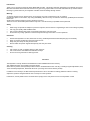
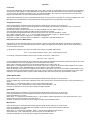
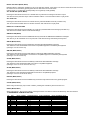
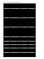
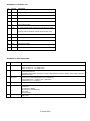
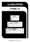
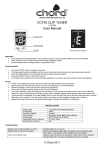
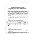
MU-series MIDI/USB Keyboard Controllers MU25 MU49 MU61 25-note MIDI/USB Controller Keyboard 49-note MIDI/USB Controller Keyboard 61-note MIDI/USB Controller Keyboard (169.011) (169.012) (169.013) User Manual Features 25/49/61 keys with touch velocity sensitivity (5 x velocity curves and selectable keyboard split) Assignable control pedal (switch or continuous) inputs (1 for MU25, 2 for MU49 & MU61) Assignable slider control Pitch Bend Wheel and Modulation Wheel (assignable) 4 x assignable rotary controls (2 banks) and 2 data entry buttons MIDI and USB output (powered by 9Vdc or USB) Compatible with Win XP/Vista and Mac OSX, plug-and-play, hot swappable Compatible with major audio and sequencer software www.chordmusic.co.uk Introduction: Thank you for choosing a Chord MU series MIDI/USB controller. This product has been designed to give ultimate control over MIDI sound modules and soundcards and form a key part of any project studio or live multi-instrument set-up. Please read the following to get the best from your keyboard controller and avoid damage through misuse. Warning: To prevent the risk of fire or electric shock, do not expose any of the components to rain or moisture. If liquids are spilled on the surface, stop using immediately, allow unit to dry out and have checked by qualified personnel before further use. Avoid impact, extreme pressure or heavy vibration to the unit. There are no user serviceable parts inside the keyboard – refer all servicing to qualified service personnel. Safety When using an optional DC adapter to power the keyboard, ensure that it is a regulated type with correct voltage & polarity Use only good quality USB and MIDI leads Only connect standard foot switch or expression pedal to the rear jack inputs. Do not allow any foreign particles to enter the keyboard through connectors or control apertures Placement Position the keyboard on a solid, flat surface or strong, stable keyboard stand with adequate grip to hold steady Keep out of direct sunlight and away from heat sources. Keep away from damp or dusty environments. Ensure cables and power supplies are kept tidy and away from harm Cleaning Use a clean dry cloth (or slightly damp) to clean surfaces. Use a soft brush to clear debris from between the keys Do not use strong solvents for cleaning the unit. Functions The keyboard is velocity sensitive with additional functions labelled above each note key. This additional function is accessed by the EDIT button. When EDIT is pressed, the keyboard provides functions as labelled above each note key, including Program Adjustment, Dual, Touch Sensitivity Adjustment, Numerical values etc. (the range of functions varies by model) In addition to the note keys, the MU-series keyboards have a set of controllers for setting parameter values or offering expression (creative changes/variances of the sound) for on-the-fly effects Furthermore, control pedals can be connected to the input(s) on the rear panel for even more expression control Top Panel 1. MODULATION Wheel - Expression wheel, assignable to one of 148 MIDI control parameters. Initial setting is MIDI control number 1: Modulation. 2. PITCH BEND Wheel – Spring loaded expression wheel, assignable to one of 148 MIDI control parameters. Initial setting is MIDI control number 146: Pitch Bend 3. DATA +/- Buttons – Increment/decrement data entry buttons, assignable to one of 160 MIDI control parameters. Initial setting is MIDI control number 154: Octave Shift 4. OCTAVE/TRANSPOSE Indicator - When either of these indicators is on, it indicates that there is an upper/lower octave shift. When the indicator flashes slowly, it indicates that there is an upper/lower transpose shift. When the indicator flashes quickly, it indicates that there is a simultaneous upper/lower octave and transpose adjustment. When the indicator is off, there is no octave or transpose shift. 5. EDIT Button – Switches edit function of note keys on/off 6. EDIT Indicator – Indicates that the EDIT function is active (keys will operate as labelled above each note) 7. SLIDER – Fader style controller, assignable to one of 148 MIDI control parameters. Initial setting is MIDI control number 147: Master Volume 8. 3-digit LED Display – Shows program/parameter values for MIDI and EDIT functions 9. SWITCH Button – Toggles the rotary dials between 2 groups of control settings: R1-R4 / R5-R8 10. Dial Function Group LEDs – Indicate which group of parameters is active for rotary dials. 11. R1- R8 Dials – 4 data entry dials, individually assignable to one of 160 MIDI control parameters, divided across 2 groups. Initial channel of R1-R4 is 0. Initial controller numbers are 152, 153, 156, 157, which control Program, Channel, Tempo and Keyboard Velocity Curve respectively. The initial channels of R5-R8 are 0-3. Initial controller number is 7, which controls the volume of channels 0-3 respectively. The parameter group of R1-R4 and R5-R8 is switched by the SWITCH button. 12. Constant Controller Parameter chart – A table showing standard MIDI parameter values Rear Panel 1. 2. 3. 4. 5. 6. MIDI OUT – 5-pin DIN MIDI output to control external sound module or keyboard PEDAL A – Pedal A input 6.3mm jack for switching or continuous type pedal control, assignable to one of 152 controllers. Initial setting is Soft Pedal. PEDAL B – Pedal B input 6.3mm jack for switching or continuous type pedal control, assignable to one of 152 controllers. Initial setting is Sustain Pedal. USB – USB type B connector for connecting to PC or Mac computer DC9V – Input jack for optional 9Vdc power adapter (300mA, polarity positive-to-centre) OFF/ON – Power switch Operation Connection The MU-series keyboards can be used directly with a PC or Mac computer to provide MIDI control in a software sound module or multi-track recording package. For this application, the USB socket on the rear panel should be connected to a spare USB port on the computer (a USB lead is supplied for this) – this will transfer MIDI to the computer and provide power to the MU-series keyboard. The MIDI OUT can also control external devices in this setup. The MU-series keyboards can also control MIDI devices when not connected via a computer, by connecting the MIDI OUT to the MIDI input of the controlled device and powering the MU-series keyboard via an optional 9Vdc power adapter. Assignable Controllers Press the EDIT button and the EDIT LED will be light to indicate that the note keys are in EDIT mode. Press the ASSIGN key to enter controller assign mode, the LED display will show CHO, prompting the user to “choose” the controller that needs to be assigned. Operate the required controller to select it (e.g. to assign SLIDER, move the Slider to select it) The LED display will show the MIDI controller number of the selected controller Input the desired assignable parameter value with number keys (0-9), and press ENTER to confirm (e.g. if Slider is selected, input “1”, ”4”, ”7” and the Slider will be set to MIDI control 147 - Master Volume). Assignable controller reference: Appendix 1- Assignable controller List Assignable controller parameters reference: Appendix 2 - Assignable Controller Parameter List. Pedal Resistance Curve (MU49, MU61) The response curve of the pedal interface can be tailored to match control pedals with different specifications and electrical resistance values. This can be adjusted by trial and error, testing the response of the pedal for various values. Alternatively, it can be calculated as follows… To calculate the resistance curve value for Pedal A (PA CURVE) or Pedal B (PB CURVE) Curve = (128 x Pedal resistance value) / (10K + Pedal resistance value). For example, if the pedal resistance value is 10K, the value of PA Curve or PB Curve is… 128 x10K / (10K + 10K) = 64. For the pedal’s electrical resistance value, please refer to the technical specifications provided by pedal manufacturer. The initial value of resistance curve is 64, adaptable to most control pedals in the market. When using a switching type pedal, the recommended resistance curve value is also 64. When DATA +/- is assigned as PA CURVE or PB CURVE, the DATA +/- buttons can be used to adjust resistance curve values. Press both DATA + and - simultaneously to set the resistance curve value to initial 64. When the dials (R1-R4 or R5-R8) are assigned as PA CURVE or PB CURVE, they can be used to adjust pedal resistance value. Press EDIT button to enter keyboard multi-function mode, press PA CURVE or PB CURVE multi-functional keys to enter pedal resistance curve adjustment mode, input the pedal resistance value with numeric pad, then press ENTER to confirm. TEMPO (MU49, MU61) Press the EDIT button and the EDIT LED will be light to indicate that the note keys are in EDIT mode. Press the TEMPO key to enter tempo adjustment mode, then input the tempo value with number keys. Press the ENTER key to confirm. When DATA +/- is assigned as TEMPO, it can be used to adjust MIDI tempo. Press both DATA + and - simultaneously to set the tempo to the initial value = 100 Likewise, the dials (R1-R4 or R5-R8) can be assigned to adjust TEMPO PROGRAM Press the EDIT button and the EDIT LED will be light to indicate that the note keys are in EDIT mode. Press the PROGRAM key to enter program select mode, then enter the number with the number keys. Press the ENTER key to confirm. When DATA +/- is assigned as PROGRAM, DATA +/- can be used to adjust the program (or voice). Press both DATA + and simultaneously to set the program to the initial value = 0 Likewise, the dials (R1-R4 or R5-R8) can be assigned to adjust the PROGRAM number MIDI Channel Press the EDIT button and the EDIT LED will be light to indicate that the note keys are in EDIT mode. Press the CHANNEL key to enter MIDI channel select mode, then set the channel with the number keys. Press the ENTER key to confirm. When DATA +/- is assigned as CHANNEL, DATA +/- can be used to adjust the MIDI channel Press both DATA + and - simultaneously to set the program to the initial value = 0 Likewise, the dials (R1-R4 or R5-R8) can be assigned to set the MIDI channel TRANSPOSE (MIDI control number 155) When DATA +/- is assigned as TRANSPOSE, DATA +/- can be used to shift the pitch +/- 12 semitones Press both DATA + and - simultaneously to set the program to the initial value = 0 Likewise, the dials (R1-R4 or R5-R8) can be assigned to set the TRANSPOSE OCTAVE (MIDI control number 154) When DATA +/- is assigned as OCTAVE, DATA +/- can be used to shift the pitch +/- 3 octaves Press both DATA + and - simultaneously to set the program to the initial value = 0 Likewise, the dials (R1-R4 or R5-R8) can be assigned to set the OCTAVE DUAL Press the EDIT button and the EDIT LED will be light to indicate that the note keys are in EDIT mode. Press the DUAL key to enter dual layer mode, the layered program can be set as per PROGRAM above DUAL function overrides the SPLIT function (details below) Pressing EDIT and the DUAL key cancels this function SPLIT (MU49, MU61) Press the EDIT button and the EDIT LED will be light to indicate that the note keys are in EDIT mode. Press the SPLIT key to enter split keyboard mode, SPLIT function cannot be used at the same time as DUAL function Pressing EDIT and the SPLIT key cancels this function SPLIT POINT Press the EDIT button followed by the SPLIT POINT key to select the keyboard split point. The LED display will show CHO, prompting the user to “choose” the controller that needs to be assigned. Press the key at the desired split point and the 2 keyboard zones will be set. MTC Pressing the EDIT button followed by the MTC key sets MIDI Time Code (F8) to be transmitted from the keyboard to the device it is controlling or to the computer it is attached to. Pressing EDIT and MTC again switches this function off again. Active Sensing (MU49, MU61) Pressing the EDIT button followed by the ACT key sets Active Sensing (FE) to be transmitted from the keyboard to the device it is controlling or to the computer it is attached to. Pressing EDIT and ACT again switches this function off again. LOCK (MU49, MU61) Press the EDIT button followed by the LOCK key to lock out the keyboard’s controllers. In this mode, the keyboard is active but all other controllers are deactivated. Pressing EDIT and LOCK again cancels this function. MUTE Press the EDIT button followed by the LOCK key to stop the MIDI output signal from the keyboard. Pressing EDIT and MUTE again cancels this function. SNAP SHOT Press the EDIT button followed by the SNAPSHOT key to send a controller snapshot. This transmits all current controller values (PITCH/MOD/SLIDER/ROTARIES) over MIDI simultaneously. UPLOAD/DOWNLOAD The user settings stored in the MU-series keyboard can be stored to and re-called from a computer connected to it via USB. These settings are transmitted as a SYSEX (SYStem EXclusive) file, which can be recorded into a software MIDI sequencer. Different software packages may vary in the way these are stored and handled. Please refer to the help files in the particular software package for information on how to store SYSEX information from an external MIDI device. Set the MIDI software package to receive or record SYSEX data Press EDIT then UPLOAD The LED display will show “SEu” to indicate uploading and then “don” to indicate complete To receive stored SYSEX data from the computer, prepare the software to play back the SYSEX file. Press EDIT then DOWNLOAD and play the file back from the MIDI software package. The LED display will show “SEd” to indicate downloading and then “don” to indicate complete PEDAL POLARITY (MU49, MU61) Different switch or expression pedals may vary in the switching polarity. If the switch is on when it should be off and vice versa, the switch can be reversed by pressing EDIT and PA POLARITY or PA POLARITY Use the DATA +/- to select the required polarity for PA (pedal A) or PB (pedal B) ALL SOUND OFF (MU49, MU61) Pressing the EDIT button then the ALL SOUND OFF key transmits a message to kill sound output. The All Sound Off (controller 120) is useful if software crashes or a sound module “sticks” in play mode ALL NOTE OFF Pressing the EDIT button then the ALL NOTE OFF key transmits all MIDI notes off (controller 123) This can be useful if a MIDI device or software “freezes” with notes stuck in a play state. RESET ALL CONTROLLERS Pressing the EDIT button then the RESET ALL CTRL key transmits MIDI reset message (controller 121) This returns all controller values to their default settings GM/GS/XG ON (MU25) Pressing the EDIT button then the GM/GS/XG ON key transmits the GM/GS/XG initialisation messages This sets any or all 3 standards on for any GM, GS or XG devices being controlled by the keyboard GM ON (MU49, MU61) Pressing the EDIT button then the GM ON key transmits the GM initialisation message This switches on the General MIDI sound-set for compatible equipment controlled by the keyboard (message = F0 7E 7F 09 01 F7) GM2 ON (MU49, MU61) Pressing the EDIT button then the GM2 ON key transmits the GM2 initialisation message This switches on the General MIDI 2 sound-set for compatible equipment controlled by the keyboard (message = F0 7E 7F 09 03 F7) GS ON (MU49, MU61) Pressing the EDIT button then the GS ON key transmits the GS initialisation message This switches on the General Standard sound-set for compatible equipment (message = F0 41 10 42 12 40 00 7F 00 41 F7) XG ON (MU49, MU61) Pressing the EDIT button then the XG ON key transmits the XG initialisation message This switches on the eXtended General MIDI sound-set for compatible equipment (message = F0 43 10 4C 00 00 7E 00 F7) PRESET (MU49, MU61) Pressing the EDIT button then the PRESET key returns the keyboard back to factory preset program CLEAN (MU49, MU61) When using number keys (0-9) to enter numbers, pressing the CLEAN key sets the number to 0 RESET (MU49, MU61) When using DATA+/- keys to enter values, pressing the DATA+ and DATA- buttons simultaneously sets the number to 1: ASSIGNABLE CONTROLLER LIST NO. 1 2 3 4 5 6 7 8 9 10 11 12 13 14 ITEM Data +/Slider Wheel P Wheel M Pedal A Pedal B R1 R2 R3 R4 R5 R6 R7 R8 INITIAL CHANNEL 0 0 0 0 0 0 0 0 0 0 0 1 2 3 PARAMTER RANGE 0 - 159 0 - 147 0 - 147 0 - 147 0 - 151 0 - 151 0 - 159 0 - 159 0 - 159 0 - 159 0 - 159 0 - 159 0 - 159 0 - 159 INITIAL PARAMETER 154 147 146 1 64 67 152 153 156 157 7 7 7 7 INITIAL PARAMETER VALUE 0 0 64 0 0 0 0 0 100 0 100 100 100 100 APPENDIX 2: ASSIGNABLE CONTROLLER PARAMETER LIST CONTROLLER NO. 0 1 2 3 4 5 6 7 8 9 10 11 12 13 14 - 31 32 33 34 35 36 37 38 39 40 41 42 43 44 - 63 64 65 66 67 68 69 70 71 72 73 74 75 76 77 78 79 80 - 83 84 85 - 90 91 92 93 94 95 96 97 98 99 100 101 102 - 119 120 121 122 123 124 125 126 127 128 129 130 131 132 133 134 135 CONTROLLER NO. 136 137 138 139 140 141 142 143 144 145 146 147 148 149 150 151 152 153 154 155 156 157 158 159 DEFINITION Bank Select MSB Modulation MSB Breath MSB Controller Foot Controller MSB Portamento time MSB Data Entry MSB Channel Volume MSB Balance MSB Controller Panpot MSB Expression MSB Effect Control 1 MSB Effect Control 2 MSB Controller Bank Select LSB Modulation LSB Breath LSB Controller Foot Controller LSB Portamento time LSB Data Entry LSB Channel Volume LSB Balance LSB Controller Panpot LSB Expression LSB Controller Sustain Portamento Sostenuto Soft Pedal Legato FootSwitch Hold 2 Sound Controller Resonance Release Time Attack Time Cutoff Decay Time Vibrato Depth Vibrato Depth Vibrato Depth Sound Controller Controller Portamento Control Controller Reverb Effects Chorus Effects Effects RPN Increment RPN Decrement NRPN LSB NRPN MSB RPN LSB RPN MSB Controller All Sound Off Reset All Controllers Local Control All Notes Off OMNI Off OMNI On Mono Poly Pitch Bend Sensitivity(RPN) Channel Fine Tuning(RPN) Channel Coarse Tuning(RPN) Modulation Depth range(RPN) Vibrato Rate(NRPN) Vibrato Depth(NRPN) Vibrato Delay(NRPN) Filter Cutoff Frequency(NRPN) DEFINITION Filter Resonance(NRPN) EQ Low Gain(NRPN) EQ High Gain(NRPN) EQ Low Frequency(NRPN) EQ High Frequency(NRPN) EG Attack Time(NRPN) EG Decay Time(NRPN) EG Release Time(NRPN) Polyphonic key pressure After touch Pitch Bend Master Volume Start(MTC) Continue(MTC) Stop(MTC) Reset(MTC) Program Global Channel Octave Transpose Tempo Keyboard Curve Pedal A Curve Pedal B Curve INITIAL VALUE 0 0 127 0 127 0 2 100 64 0 64 127 0 0 0 0 0 127 0 127 0 0 127 64 0 64 127 0 0 0 0 0 0 0 64 64 64 64 64 0 64 64 64 64 0 0 0 40 0 0 0 0 0 0 0 0 0 0 0 0 0 0 0 0 0 0 0 2 64 64 64 64 64 64 64 INITIAL VALUE 64 64 64 64 64 64 64 64 100 100 64 100 0 0 0 0 100 0 64 64 VALUE RANGE 0 - 127 0 - 127 0 - 127 0 - 127 0 - 127 0 - 127 0 - 127 0 - 127 0 - 127 0 - 127 0 - 127 0 - 127 0 - 127 0 - 127 0 - 127 0 - 127 0 - 127 0 - 127 0 - 127 0 - 127 0 - 127 0 - 127 0 - 127 0 - 127 0 - 127 0 - 127 0 - 127 0 - 127 0 - 127 0 - 127 0 - 127 0 - 127 0 - 127 0 - 127 0 - 127 0 - 127 0 - 127 0 - 127 0 - 127 0 - 127 0 - 127 0 - 127 0 - 127 0 - 127 0 - 127 0 - 127 0 - 127 0 - 127 0 - 127 0 - 127 0 - 127 0 - 127 0 - 127 0 - 127 0 - 127 0 - 127 0 - 127 0 - 127 0 - 127 0 - 127 0 - 127 0 - 127 0 - 127 0 - 127 0 - 127 0 - 127 0 - 127 0 - 127 0 - 127 0 - 127 0 - 127 0 - 127 0 - 127 0 - 127 0 - 127 VALUE RANGE 0 - 127 0 - 127 0 - 127 0 - 127 0 - 127 0 - 127 0 - 127 0 - 127 0 - 127 0 - 127 0 - 127 0 - 127 0 - 127 0 - 15 -3-3 - 12 to 12 20 - 250 0-4 1 - 127 1 - 127 APPENDIX 3: LED Status List NO. STATUS DEFINITION 1 xxx 3 Digit Display 2 xx Upper Transpose Value 3 - xx Lower Transpose Value 4 x Upper Octave Value 5 -x Lower Octave Value 6 CHO (1) Under Assign Mode: indicate the controller to be assign. (2) Under Split Point Mode: indicate keyboard Split point. 7 ON/OFF Selected function On/Off, or pedal polarity positive/negative. 8 don Selected function done. 9 Err Operation error. 10 SEu Parameters upload. 11 SEd Parameters download. APPENDIX 4: SPECIFICATIONS NO. ITEM SPECIFICATIONS 1 Keyboard 2 Function 3 Panel &Indicator 4 Display MU25: 25 Keys, C2 - C4, Initial Touch. MU49: 49 Keys, C1 - C5, Initial Touch. MU61: 61 Keys, C1 - C6, Initial Touch. MIDI Data: Program Select, Bank Select, Sequencer Control, MTC, Controller Change, GM, GS, XG System Reset and etc. Controllable Parameters: Transpose, Octave, MIDI Transmit Channel, Velocity Curve Adjust, Keyboard Split Point and etc. 4xAssignable Dials. 1xDial Group Function Shift Button (incl. 2 Indicators.) 2xAssignable Data +/ - Buttons (incl. 2 Indicators.) 1xEdit Button (incl. 1 Indicator.) 8 Segments, 3 Digits LED. 5 Input & Output 6 Power Supply 1xMIDI Out. 1xUSB Port. 1xPedal Input. (MU25) 2xPedal Inputs. (MU49/MU61) 1xDC Input. 1xPower Switch. 9V DC. USB Power. © Chord 2011