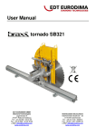
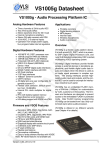
1
User Manual
Preset Counter
Signo 721.2/.3/.4
Sach-Nr. 2 721 205; 10/2009
Deutsch Originalsprache
Part.-No. 2 721 205; 10/2009
Original language German / English translated from German
Deutsch
Vorwahlzähler
English
Benutzerhandbuch
Table of Contents
General Information
1.1
1.2
1.3
1.4
1.5
1.6
88
Information about the Operating Instructions
Explanation of symbols
Limitation of Liability
Copyright protection
Guarantee conditions
Customer Service
2 Safety
2.1
2.2
2.3
2.4
2.5
2.6
3
88
90
91
92
92
92
93
Intended Use (Proper Use)
Assembly, connecting, programming
Responsibilities of the machine/plant manufacturer and operator
Staff-related requirements
Special hazards
Safety devices
Setup and Operation
93
94
97
98
99
101
102
3.1 Dimension Sheet / Counter Installation
3.2 Connecting the Counter
3.3 Display
103
104
108
85
English
1
Table of Contents
3.4 Keyboard functions
3.5 Overview of Operating Elements
4
110
112
Programming presets, correction values, prescaler and signal times
4.1 Overview of programming the presets, correction values and prescaler
4.2 Programming presets, correction values and prescaler
4.3 Programming the signal times
5
Description of the Pulse Counter
5.1
5.2
5.3
5.4
6
113
113
114
116
118
Description of the Pulse Counter
Signal diagrams – counter input signals
Signal diagrams – counter output signals
Programming the counter function codes
118
123
126
128
Replacing the 0721.1 with 0721.2, .3, .4
136
6.1 Replacing the 0721.1 with 0721.2, .3, .4
6.2 Changes on wiring at the plug-type connectors
6.3 Changes on the switch- and potentiometer settings
86
136
138
150
7
Technical Data
152
8
Transport, Packaging, Storage
159
9
Maintenance and cleaning
159
10Malfunctions
160
11
163
Spare Parts
12 Dismantling and Disposal
163
13 Ordering Information
164
14Accessories
166
87
English
Table of Contents
1 General Information
1
General Information
1.1 Information about the Operating Instructions
These operating instructions provide important information about the handling of the counter. To ensure safe
operation it is vital that the safety information and instructions are strictly observed.
The counter has been designed for industrial use and for installation in machinery or industrial plants.
The manufacturer of the machine/plant in which the counter is used has to ensure that the function of the counter is properly described in the Operating Instructions of the machine or plant, and that the description is in accordance with manufacturer’s programming functions.
The manufacturer’s safety rules shall be applicable.
In addition, the regulations concerning the prevention of accidents and general safety information shall be adhered to.
Before starting any work on the machine/plant, the operating instructions and in particular, the Safety chapter
and the respective safety information must be fully read and considered.
These operating instructions are an integral part of the product and must be maintained in the direct vicinity of
the machine/plant and in a place that is readily accessible for the operating staff.
88
1 General Information
These operating instructions contain important information concerning the installation, connection and programming of the counter.
-
-
-
-
Programming of the function codes
Programming of the signal times
Programming of the presettings
Programming of the prescaleer
Before starting to run the machine/plant is in operation, all functions that are not allowed to be changed by the operator
have to be blocked.
The executed programming functions have to be documented.
The counter 0721.2xx / 0721.3xx und 0721.4xx are designed to replace the counter 0721.1xx. See chapter 6.
89
English
Description of the programming sequence:
1 General Information
1.2 Explanation of symbols
Warnings
The warnings in these operating instructions are designated by symbols. Signal words at the beginning of the
warnings indicate the severity of a safety hazard.
These notes have to be observed by all means, and all actions have to be taken with utmost care so as to prevent
any accidents or damage or personal injury.
Danger!
This warning indicates a direct safety hazard, which may lead to serious injuries or
even death if preventative action is not taken.
Warning!
This warning indicates a possible safety hazard, which may lead to serious injuries
or even death if preventative action is not taken.
Caution!
This warning indicates a possible safety hazard, which may lead to minor damage
or injuries if preventative action is not taken.
90
1 General Information
Tips and recommendations.
This symbol is used to point out to useful tips and recommendations and information ensuring efficient and trouble-free operation.
1.3 Limitation of Liability
The information and notes contained in these operating instructions were gathered in accordance with the applicable standards and regulations, the state-of-the-art, as well our long-standing experience and know-how.
The manufacturer shall not assume any liability for damage caused by:
-
-
-
-
-
Non-adherence to the operating instructions
Improper use
Employment of unskilled or untrained personnel
Makeshift changes or manipulation
Opening of the multifunction counter
91
English
Note!
This symbol indicates a potentially hazardous situation, which may lead to damage
to property or to the environment if preventative action is not taken.
1 General Information
1.4 Copyright protection
The operating instructions must be treated confidentially and used exclusively by the personnel responsible for
the setup, maintenance, repair and operation of the machine/plant. Disclosure of these operating instructions to
any third parties shall not be permissible without the prior written consent of the manufacturer.
The data and information stated here, including text, drawings, images and other
illustrations, are protected by copyrights and subject to industrial property rights.
Any misuse of such information shall be subject to prosecution.
1.5 Guarantee conditions
Our guarantee conditions are available for download from our homepage at www.hengstler.com – DOWNLOAD –
General Terms & Delivery Terms.
1.6 Customer Service
Our customer service is available to provide technical information and assistance for our customers. Detailed information on your responsible contact partner is given on our homepage (www.hengstler.com) under Contact and
Directions.
92
2 Safety
2Safety
This section provides an overview of all the important safety-relevant aspects to ensure best possible protection
of the operating personnel as well as safe and trouble-free operation. Non-adherence to the instructions given in
this manual may result in considerable safety hazards.
The counter is exclusively designed and constructed for the intended use and purposes described here.
The counter serves together with a corresponding encoder for the counting of piece numbers, lengths, flow
rates, as well as for the controlling and monitoring of machinery and equipment by sending control signals.
Warning!
Safety hazards due to improper use / misuse!
Using the counter for any purposes other than the ones described within the scope
of intended use may cause hazardous situations.
Claims for damages resulting from any kind of misuse shall be expressly excluded.
93
English
2.1 Intended Use (Proper Use)
2 Safety
2.2 Assembly, connection, programming
These counters are built and tested in accordance with IEC/EN 61010-1, Protection Class II. They have left the
factory in a condition that is in compliance with all safety-relevant requirements.
In order to maintain this condition and ensure operational safety, the User is requested to observe the safety notes and warnings given in these operating instructions.
Danger!
Risk of safety hazards due to incorrect/faulty assembly and connection.
• The max. operating voltages must not be exceeded!
• 12 – 30VDC and 24VAC multifunction counters have to be operated at safety extra-low voltages (SELV) in or
der to prevent hazardous shock currents
• An external fuse has to be provided to protect the multifunction counter (see Chapter 7, Technical Data).
• Installation and assembly shall be carried out by skilled and trained electricians only.
• Do not connect the counter without making sure that it no longer carries any live voltages. Always separate it from the mains supply before connecting.
• Make sure that live terminals are properly protected against inadvertent contact.
94
2 Safety
• To ensure proper protection of terminals against hand contact, make sure that the live conductors are
properly connected to the terminals.
• Do not establish any connections with non-allocated (“NC”) terminals.
• Counters may only be operated in a properly installed condition.
• The installation and wiring environment has considerable impact on the electromagnetic compatibility of the counter. Therefore, electromagnetic compatibility of the entire plant has to be ensured during the installation.
• The fabricator of these complete units or systems takes responsibility for conforming to theCE Directive.
• In areas presenting the risk of ESD (electrostatic discharge), make sure to use ESD-protected plugs and
switches during the installation.
•
If the functions “prescaler input”, “preset input”, “correction value” and “key reset” are not allowed to be used by the machine/plant operator, access to these functions must be blocked for machine operators. Depending on the machine/plant design or concept, non-permissible input may impair the operational safety and
function of the machine or plant.
• In oily environments a delamination of the front sheet is possible. Therewith the tightness of the counter may be affected. We suggest to use a protection cover as a countermeasure (see chapter 7, 9 and 14).
95
English
• If safe operation seems to be impaired, make the counter inoperable and secure it against inadvertent
operation.
2 Safety
• It has to be ensured, that during transient processes (approx. 2 s till the display test disappears) and power down processes no counting pulses or control signals are applied to ensure, that misinterpretations of the
logic do not happen.
After an unplanned power drop adequate actions may be necessary. (E.g. Going back to the reference point)
If the supply voltage drops below 9 V when switching off the device or due a power breakdown, all outputs are switched off immediately
Gefahr:
Der Hersteller der Steuerung / Anlage hat sicherzustellen, dass sich hieraus keine
Risiken ergeben.
• The machine/plant manufacturer shall be responsible for the preparation of operating instructions / plant
description including the following:
o
o
o
Description of functions according to the programming of the counter;
Description of the settings to be adjusted by the machine/plant operator;
Information concerning the occupational safety requirements and possible hazards arising from the operation of the machine/plant.
96
2 Safety
2.3 Responsibilities of the machine/plant manufacturer and operator
Counters are designed for installation in machines/plants. Therefore, the manufacturer and operator of the
machine/plant are subject to the legal obligations concerning occupational safety and health.
• The machine/plant manufacturer shall be obligated to ensure that all the requirements mentioned in Section 2.2 be fulfilled during the assembly, connection and programming.
•
The operator shall obtain all the required information about the applicable occupational safety rules. In
addition, the operator shall be obligated to prepare a risk assessment of possible hazards that may arise due to the special working conditions at the place of installation of the machine/plant. This risk assessment shall be documented in the form of operating instructions for the machine/plant.
• Throughout the entire operating time of the machine/plant the operator shall be obligated to check if the operating instructions prepared are in accordance with the latest status of requirements and, if required, make the appropriate adjustments.
• The operator shall ensure that all staff members who are involved in the machine/plant operation have read and fully understood these instructions. Moreover, the operator shall be obligated to train the operating per
sonnel at regular intervals and inform them about any potential hazards.
97
English
Besides the safety notes given in these operating instructions, the relevant rules and regulations concerning
safety and the prevention of accidents, and the applicable environmental requirements have to be met. In
particular:
2 Safety
• The operator shall ensure that the operation and cleaning of the machine/plant is exclusively carried out by skilled and trained personnel.
• The operator shall ensure that all maintenance and repair work shall only be carried out by skilled and trained personnel.
2.4 Staff-related requirements
Warning:
Danger of personal injuries if handled by insufficiently qualified staff!
Improper handling may cause severe personal injuries and damage to property.
• Actions requiring special skills have to be carried out only by the personnel designated in the appropriate
sections of these instructions.
• Keep unqualified personnel away from hazard areas.
98
2 Safety
The following staff qualification requirements have been defined for the various scopes of
activities:
•
Skilled personnel
Due to their educational and professional skills, know-how and experience, as well as due to their knowledge of the relevant regulations, these persons are capable of executing their assigned tasks and recognize poten-
tial hazards independently.
•
Skilled and trained electricians
Due to their educational and professional skills, know-how and experience, and due to their knowledge of the relevant regulations in the field of electrical engineering, these persons are capable of executing electrical work and recognizing potential hazards independently.
2.5 Special hazards
This section indicates certain residual risks, which may arise as a result of the risk assessment.
The safety information and warnings given here and in the following chapters of these instructions have to be
observed in order to reduce any health hazards and avoid hazardous situations.
99
English
• Instructed personnel
These persons have been instructed by the operator with regard to the tasks assigned and the potential
hazards caused by improper handling.
2 Safety
Danger!
Lethal hazard of shock current and electric shock!
Any contact with hazardous live components presents a direct lethal hazard. Damages of the insulation or individual components present a potential lethal hazard.
• In the event of any damage to the insulation, immediately disconnect the voltage supply and initiate the appropriate repair work.
• Any work on the electrical plant has to be carried out by skilled and trained electricians only.
• Before commencing your work on the electrical system, disconnect it from the mains supply and check that it no longer carries any live voltages.
• Prior to conducting any maintenance, cleaning or repair work, disconnect the mains supply and secure it against inadvertent switching on.
• Do not short-circuit or make fuses inoperable.
100
2 Safety
2.6 Safety devices
The counter itself does not include any installed safety devices.
These safety devices have to be attached externally.
Protect the electrical supply of the counter by means of external fuses (see Chapter 7, Technical Data).
101
English
Warning!
Lethal hazard by non-functional safety devices!
Safety devices are provided to ensure a maximum of operational safety.
3 Setup and Operation
3
Setup and Operation
1Display
2 Operating keys
3 Flat gasket
4Bracket
5Enclosure
6 Plug for DC or sensor supply;
Electronic inputs and outputs
7 Connection terminal
AC supply and relay contacts
8 Circuit diagram
102
3 Setup and Operation
English
3.1 Dimension Sheet / Installation of Multifunction Counter
bracket
103
3 Setup and Operation
3.2 Connecting the Counter
2 721 209
2 721 212
VDC 2 relays / 2 transistors
VAC Transformer 2 relays / 2 transistors
104
English
3 Setup and Operation
VDC 1 relay / 1 transistor
VAC Transformer 1 relay / 1 transistor
105
3 Setup and Operation
VAC switching power supply 2 relays / 2 transistors
106
VAC switching power supply 1 relay / 1 transistor
3 Setup and Operation
Caution!
It is not allowed to contact the encoder to a direct current line voltage without
protective circuit for EMC. For cable lenths > 30 m a protective circuit is always
necessary!
When programming the input level to TTL an additional protective circuit is
necessary.
We recommend the installation in a metallic environment.
107
English
The plug has to be disconnected from the counter before the cables are fastened
by means of screws or screw-type terminals.
3 Setup and Operation
3.3Display
After switching on, all segments and characters are illuminated for approx. 2 seconds; then the display changes
over to the Display or Programming Mode.
The display is available in three different versions:
Reflective: black digits on a bright reflecting background
Positively transflective: black digits on an illuminated background*
Negatively transmissive: red illuminated digits on a black background*
* Currently not available
108
English
3 Setup and Operation
109
3 Setup and Operation
3.4 Keyboard functions
Signo 721 is equipped with four keys:
Enter - Button
SHIFT - Button
UP - Button
These keys are assigned different context-dependent functions.
If pressed together with POWER ON (keep keys pressed and switch on the device):
+
Programming function codes
+
Programming mono-time
110
Reset - Button
3 Setup and Operation
+
For setting the presets, prescaler and correction values. Which each
pressing of the ENTER-Button, you will get to the next value.
When using the SHIFT-Button while setting the values, the next
digit to the left is selected.
When using the UP-Button while programming, the value is raised
by one.
When pressing the UP-Button and the RESET-Button at once, the
value is reset.
In the setting menu, the current value is set to 0 and the prescaler
to 1,0000.
When in the programming mode for function codes, by pressing
these two buttons you can switch between text and numerical
display.
111
English
During Operation:
3 Setup and Operation
3.5 Overview of Operating Elements
Display Mode
E
= Programming
Mode
12345
E + shift at power on
E + up at power on
Programming Mode
preset value
correction value
Prescaler
Reset
up + R
0
= Function Parameter
= Signal times
Function parameters:
Signal times
for
Preset 1
Preset 2
Operat. Mode
Count frequency
Decimal piont
Reset Behavior
Set/Reset-Mode
Keylock
Output signals
npn/pnp selection
Applic. Input/Output
+ many other function parameters
112
E
4 Programming the presets, correction values and prescaler
4.1 Overview of programming the presets, correction values and prescaler
Counter with 2 presets
Prescaler
Prescaler
Correction value
Correction value
Preset
Preset 2
English
Counter with preset
Preset 1
Entering value
Entering value
The first programmable value is always
the preset
The first programmable value is always
the preset 1
113
4 Programming the presets, correction values and prescaler
4.2 Programming presets, correction value and prescaler
By pressing the E-button you get to the setting of presets, correction value and prescaler. With every pressing of
the E-button you will get to the next settable value. If passed through all values, the next pressing of the E-button saves all values and the counter returns to the display mode.
In the programming mode the selected digit can be changed by using the SHIFT-button. Each time pressing the
shift button the digit one to the left is selected. With the UP-button the value of the selected digit is raised by
one.
Presets and correction values can be positive or negative. The prescaler value can only be positive.
If the fifth digit is changed from 9 to 0 the leading sign is changed.
If presets, correction values or prescaler are locked with F31-F36, these will not be shown.
When setting the correction value, first the counting value is on the display. This value can be changed and will
be saved when returning to the display mode.
When leaving the programming mode, presets and correction value will be checked if the set values are able to
reach. This is necessary as with a prescaler > 1 not all values can be reached.
Presets and correction values will be rounded to the next available value.
If in the programming mode no button is used for 16 seconds, the counter returns to the display mode.
The values which have been saved by then will be kept.
114
4 Programming the presets, correction values and prescaler
Switching to the programming mode, switching to the
next value
Selecting the digit: (blinking)
Raise value by one
After run through all values: Save and back to display mode
Preset 1
+
Preset and correction values
reset to 0
Prescaler set to 1,0000
Preset 2
Preset
(at a preset)
Correction value
Prescaler
115
English
Pressing the UP- and the R-button at the same time the preset and correction value will be set to 0, the prescaler
to 1,0000.
4 Programming the presets, correction values and prescaler
4.3 Setting the signal times
If with the function codes F7 and/or F8 an output signal is set to monostabil, the following programming sets the
signal time. You get to the programming mode by pressing the buttons E + UP while switching on the counter.
In the programming mode, the digit that you want to change is selected by the SHIFT-button. This digit is
blinking. With each pressing of the SHIFT-button, the selected digit is going one position to the left. With the
UP-button the value of the selected digit is raised by one.
The maximum settable time is 599,99 s.
By pressing the E-button the counter switches to the setting of the next signal time. Pressing the E-button again
saves the set values and returns to the display mode. For counters with one relay, only one signal time is possible
to set.
Pressing UP- and R-button at the same time, the value is set to zero.
116
4 Programming the presets, correction values and prescaler
+
Selecting digit:
(blinking)
Raise value by one
Changing to the next signal time or save, return to
display mode
Signal time when preset 1
+
Reset to 0
Signal time 1
Signal time 2
117
English
Pressed at the same
Time +
Power on
5 Describtion of the counter
5.1 Describtion of the counter
Factory Setting
(Defaults):
Counter mode:
Prescaler:
Sets all the function codes to the factory settings,
i.e. all codes designated with *.
The following counter modes can be selected:
Unidirectional counting, adding or subtracting;
Unidirectional counting with directional input;
Differential counting, summation (totalizing) or
phase discriminator (quad) with single, double or quadruple evaluation.
The “Prescaler” is a multiplier. Each input pulse is multiplied by the adjusted factor. The display
shows integers only.
After a reset the counter is completely reset to 0; this also includes the non-visible value of < 1.
At a prescaler of >1 not all the values are selectable. If invalid Preset values are selected, the
counter will round them up to the next possible value.
Example: PSC cannot select (reach) Preset value 7. In this case, the counter automatically
changes the Preset value to 10).
If the Prescaler is changed, this may also affect the Preset values, which may have to be changed accordingly.
Adjusting range 0,0001 to 9,9999
The Prescaler is used, for example, to convert counter pulses into meaningful units, to adapt
the units of measurements (e.g. cm-pulses to inch-pulses), or to compensate for worn measuring wheels.
118
5 Describtion of the counter
Display 2nd row:
In display mode, the second display line is not used. In the programming mode the function
codes, presets, correction values, prescaler or signal times, which are programmed in the
first display line, are shown in the 2nd display line.
Counter and control
inputs:
The counter is fitted with 3 counter and control inputs and, in addition, with an application
input (see below). These inputs are assigned various counter or control functions by means
of function code settings.
Input logic:
The input logic can be programmed to NPN or PNP, each at the
8V-level or TTL level; see Technical Data for the switching threshold.
Reset/Set:
Manual setting via keys (lockable)
Electronic setting via control input (and/or application input)
Automatic programming after reaching the main Preset
Depending on the function code the counter is:
1.) Reset: reset to 0
P 2 is the main Preset (preselect) value
During unidirectional counting the counter will add up
119
English
Formula: PSC = Desired (nominal) display / number of pulses
Example: Flowmeter 173 pulses per100 liters; display in liters
PSC = 100 / 173 = 0,5780
Example: 1 pulse per cm; display in inch
PSC = 1 / 2,54 = 0,3937
5 Describtion of the counter
or
2.) Set: reset to P 2
Signal 2 at 0
During unidirectional counting the counter will subtract
Static/dynamic Reset:
Static Reset:
Reset over the entire pulse width of the reset pulse
Dynamic Reset:
Reset via the active edge; thereafter, counter operation is
possible independently of the pulse width of the reset pulse.
Decimal point:
The decimal point is only an optical reading aid on the display and does not change the
value. For example, for a value of 1 pulse per cm, the setting 0,00 makes it easier to read the
value in m and cm.
Input damping
(Attenuation)
The inputs A and B are damped to 60 kHz.
Following maximum input frequencies are not to be exceeded:
Phasediscriminator single evaluation: A and B each 30 kHz (TTL 20 kHz)
Phasediscriminator double evaluation: A and B each 30 kHz (TTL 20 kHz)
Phasediscriminator quadruple evaluation: A and B each 15 kHz (TTL 20 kHz)
Unidirectional counting and directional input: Input A 60 kHz (TTL 20 kHz)
Differential counting, summation (totalizing): Input A + B 60 kHz in total (TTL 20 kHz)
If mechanical contacts are triggered (i.e. relays, switches, Reed contacts, etc.), the input
frequency has to be damped (attenuated) to 30 Hz, so as to filter out bounce pulses.
If damping to 30 Hz is selected, all inputs can be used with 30 Hz.
120
5 Describtion of the counter
To reach these values the amplitude thresholds are to be hold.
(See technical data - chapter 7)
The counter operates in the coincidence mode, i.e. output signals are activated after
reaching the appropriate Preset value for the programmed period of time.
P 1 and P 2 are available as relay changeover contacts and electronic output signals (PNP).
If a signal is active, this will be shown on the LCD display.
Signal times:
1.) bistable: Cleared by electronic or manual reset.
P 1= bistable – additionally cleared by signal 2
Attention: Signal 2 must not be bistable for automatic reset.
2.) monostabil: Signal times can be programmed between 0,01s und 599,99s
(see chapter 4.3)
Correction value
By selecting the menu item „Correction“ the current counter value can be corrected or
changed to every possible value.
Application Input/
Output:
6 different functions can be assigned to the application input/output. Note that only one of
these functions can be selected.
Outputs: Prescaler-output, directional output
Input: Reset, Gate, Keylock, Hold
121
English
Signals:
5 Describtion of the counter
Prescaler output:
The prescaler output is an application output.
With each increase of the counter reading the number of output pulses corresponds to the
respective number of increments.
The pulse length of the prescaler output corresponds to a frequency of1,5 kHz.
When using the prescaler output the max. count frequency is:
F max = 1500 / PSC.
So it is possible that the maximum input frequency can not be reached.
Application Keylock:
All keyboard functions can be locked (latched) individually
(Reset, Preset 1, Preset 2, Prescaler, correction value)
Lock mode: complete keylock or
Keylock depending on keylock-input (application input)
Our Tip:
After setting up the system, lock all the keyboard functions that are not allowed
to be changed by the user.
122
5 Describtion of the counter
5.2 Signal Diagrams Input signals (PNP-Logic)
Input A
Counter Input
Input B
Gate
Input C
Reset
Counter reading
1
2
3
3
4
5
0
1
2
3
2
3
4
0
1
Directional input (F1= C d r)
Input A
Counter Input
Input B
Directional input
Input C
Reset
Counter reading
1
Differential input (F1= A S r)
123
English
Unidirectional counting (F1 = C G r)
Counter reading
1
2
Summation (totalizer) input (F1= A A r)
3
2
3
4
0
1
4
3
5
2
6
1
7
2
0
0
1
1
5 Describtion of the counter
Input A
Differential
input (F1= A S r)
Adding
B
Input A
Adding
Input B
Input C
Subtracting
Reset
Input C
Reset
Counter reading
Counter reading
1
1
2
2
Summation
Phase discri(totalizer)
minator (Finput
1= Q(F1=
UAd rA) A r)
Change of rotating direction
Input
A A
Channel
Adding
Input
B B
Channel
Adding
Input C
Reset (dynamic)
Counter reading single 1
2
4
5
6
7
0
1
3
4
5
4
-1
Evaluat. (F2=0)
2
3
4
5
6
7
8
9
8
7
0
-1
-2
Counter reading double 1
Evaluat. (F2=1)
124
Counter
17ha16
P
hase direading
scriminator (F1=1 Q2
UAd3 r) 4 5 6 7 8 9 10 11 12 13 14 15 16 17 C
nge15of14
rot13
atin0g di-1
rec-2
tion-3 -4
quadruple
Reset
Counter reading
1
2
4
5
Phase discriminator (F1= QUAd r)
56Describtion
of the
7
0
1 counter
Change of rotating direction
Channel A
English
Channel B
Input C
Reset (dynamic)
Counter reading single 1
2
3
4
5
4
0
-1
Evaluat. (F2=0)
2
3
4
5
6
7
8
9
8
7
0
-1
-2
Counter reading double 1
Evaluat. (F2=1)
Counter reading
1 2 3 4 5 6 7 8 9 10 11 12 13 14 15 16 17 17 16 15 14 13 0 -1 -2 -3 -4
quadruple
Evaluat. (F2=2)
125
5 Describtion of the counter
5.3 Signal Diagrams - Output signals
Output signals monostable
Coincidence signals P 1 (F7), P 2 (F8) monostable
Counter reading
Preset 0
Preset 1
Preset 2
Reset
Signal time
P 1 (Relay)
Signaltime
P 2 (Relay)
Signal time
P 1 electronic
Signaltime
P 2 electronic
Output signals bistable
Coincidence signal time P 1 (F7), P 2 (F8) bistable
Counter reading
Preset 0
Preset 1
126
Preset 2
Reset
Signal time
P 1 electronic
5SignalDescribtion of the counter
time
P 2 electronic
Output signals bistable
Coincidence signal time P 1 (F7), P 2 (F8) bistable
P 1 (Relay)
Preset 0
Preset 1
Reset
bistable
bistable
P 2 (Relay)
P 1 electronic
Preset 2
English
Counter reading
bistable
bistable
P 2 electronic
127
5 Describtion of the counter
5.4 Programming the Counter Function Codes
Programming Mode:
Change Function
Setting:
Change
to next function:
Return to
Display Mode and save the
set function values:
+
Keep pressed and simultaneously turn Voltage On
Alternative display of the
function codes
press
+
press
press
The function codes are displayed as text in row 1.
By pressing both keys simultaneously you can change to
the numerical display (F 0 to F 35). After pressing these
keys once again the number of the selectable options will
be displayed in addition. This setting will be stored.
128
5 Describtion of the counter
F0
F1
Display
Row 1
Display
Row 2
Function
No.
Factory
Setting
(Defaults)
0*
No Function
1
All Function Codes are set to
the values marked with *
Zählbetriebsart
Input A
Input B
Input C
0*
Count. Inpt.
Gate
Reset
1
Count. Inpt.
Direction.
Input
Reset
2
Count. Inpt.
Hold
Reset
3
Count. Inpt.
Direction.
Gate
4
Adding
Input
Reset
5
Adding
Subtracting
Gate
129
English
Functionscode
5 Describtion of the counter
F2
Edge
Evaluation
/ Quadrat.
evaluation
F3
PNP/NPNLogic
6
Adding
Adding
Reset
7
Channel A
Channel B
Reset
8
Channel A
Channel B
Gate
0*
Single evaluation
1
Double evaluation
2
Quadruple evaluation
0
NPN 8 V-Level
1*
PNP 8 V-Level
2
NPN TTL-Level
130
F4
F5
F6
Inputdamping
(Attenuation)
3
PNP TTL-Level
0
30 Hz damping (e.g. for mechanical contacts)
1*
F max. (see chapter 4 and 7)
Set / Reset
0*
- Mode
Dynam/
static Reset
Reset to 0
1
Automatic reset to 0 after reaching Preset 2
2
Set to Preset 2
3
Automatic reset to Preset 2 after reaching 0
0*
Static reset (reset as long as the signal is applied)
1
Dynamic Reset (ready to count after reset (even
if reset signal is applied for a longer time)
131
English
5 Describtion of the counter
5 Describtion of the counter
F7
F8
F9
Signal
time P 1
Signalzeit
VW 2
Decimal
point
0
Disabled / No output signal
1
Bistable, reset with Preset 2 or Reset
2
Monostable setting (0-599,99 s)
0
Disabled / No output signal
1
Bistable; Reset
Cannot be used in conjunction with automatic
Reset
2
Monostable
setting (0-599,99 s)
0*
No decimal point
1
1 decimal place
2
2 decimal places
132
F20
F30
Applica.
Input/
Output
Lock Reset
key
3
3 decimal places
4
4 decimal places
0
Prescaler output
1
Directional output
2
Reset input
3
Gate input
4*
Keylock input
5
Hold input (display lock)
0*
Enable keyboard reset
133
English
5 Describtion of the counter
5 Describtion of the counter
F32
F33
F34
F35
Lock Preset 1
Lock Preset 2
Lock
Prescaler
Lock
correction
value
setting
1
Keyboard reset locked
0*
P 1 Setting enabled
1
P 1 Setting locked
0*
P 2 Setting enabled
1
P 2 Setting locked
0*
PSC setting enabled
1
PSC Setting locked
0*
Correction value setting enabled
1
Correction value setting locked
134
5 Describtion of the counter
Lock
Mode
0*
Completely locked
1
Lock depends on
Keylock Input
English
F36
135
6 Replacing the 0721.1 with 0721.2, .3 or .4
6.1 Replacing the 0721.1 with 0721.2, .3 or .4
The counter 0721.2, .3 and .4 replaces the old counter 0712.1. They only differ as to their displays.
The counter is designed with completely new hardware. Therefore the wiring of the plug type connectors
changed as well. For more information on these changes please see chapter 6.2
For the power supply has to be considered:
The connections for the DC supply are still 1 and 2. But they have been changed among each other.
New is, that now 10 = +UB and 2= 0V
The AC- power supply is connected to 9 and 10.
Danger!
Under no circumstances, the connector with the old wiring is allowed to be
plugged to the new counter. A wrong connection may lead to dangerous situations,
extensive material damage and the destroying of the counter.
136
6 Replacing the 0721.1 with 0721.2, .3 or .4
The switch-settings are replaced by the function codes, which have to be programmed correspondingly
(see chapter 5.3 and chapter 6.3)
The potentiometer settings are replaced by setting the function codes F7 and F8 to bistabil and monostabil (see chapter 5.3) and if needed, the programming of the signal times (see chapter 4.3).
The handling of the counter by the operator of the machine doesn’t change.
137
English
There are different ways for connecting the control inputs. For an optimum selection all needed
control-functions have to be considered. There are now new combinations available which were not
possible before. There are also combinations which are not possible, e.g. the prescaler output together
with the keylock input. If the buttons have to be locked this has to be done via the software. The
keylock-input is only needed if the keylock has to be controlled from the outside.
6 Replacing the 0721.1 with 0721.2, .3 or .4
6.2 Changes on wiring at the plug-type connectors
6.2.1.Version: 1 Preset with relay-output
old
new
alternative displays
0 721 101
0 721 201
07213xx reflective
0 721 102
0 721 202
07214xx backlighted
0 721 109
0 721 202
0 721 121
0 721 201
0 721 122
Power supply
DC or AC
0 721 202
Plug-type
connector
Function
Plug-type
connector
1
Power supply
DC-suppl. 0 V
2
AC-suppl. ~
9
Power supply
DC-suppl. + Ub
1
AC-suppl ~
10
2
138
Function code setting
6 Replacing the 0721.1 with 0721.2, .3 or .4
Sensor supply
Control inputs
not used
4
not used
5
not used
6
Normally closed
12
7
Center contact
11
8
Normally open
13
9
0 V sensor supply
2
10
24 VDC sensor supply
1
11
Count-input
3
F1 = 0, 1, 2, 3, 4, 5, 6
12
Reset
5
F1 = 0, 1, 2, 4, 6,
Reset at application input
6
F20=2
4
F1 = 0
5
F1 = 3, 5
6
F20 = 3
4
F1 = 2
13
English
Relay
3
Application input
as Gate
As Hold
139
6 Replacing the 0721.1 with 0721.2, .3 or .4
14
6
F20 = 5
as directional input (Up/Down)
4
F1 = 1, 3
Keylock
6
F20 = 4
select in F30 - F35
F36 = 2
PSC-output.
15
Prescaler-output
16
not used
140
6
F20 = 0
6 Replacing the 0721.1 with 0721.2, .3 or .4
old
new
alternative displays
0 721 103
0 721 201
07213xx reflectiv
0 721 104
Power supply DC or AC
0 721 202
07214xx backlighted
Plug-type
connector
Function
Plug-type
connector
Function code setting
1
Power supply
DC-suppl. 0 V
2
AC-suppl. ~
9
Power supply
DC-Vers. + Ub
1
AC-suppl. ~
10
2
0V
3
not used
4
not used
5
0V
2
141
English
6.2.2.Version: 1 Preset with transistor-output
6 Replacing the 0721.1 with 0721.2, .3 or .4
Transistor output
Sensor supply
Control inputs
6
not used
7
Out Transistor
8
8
0V
2
9
0 V sensor supply
2
10
24 VDC sensor supply
1
11
count input
3
F1 = 0, 1, 2, 3, 4, 5, 6
12
Reset
5
F1 = 0, 1, 2, 4, 6,
Reset at application input
6
F20=2
4
F1 = 0
5
F1 = 3, 5
6
F20 = 3
4
F1 = 2
6
F20 = 5
4
F1 = 1, 3
13
Application input
as Gate
As Hold
as directional input (Up/Down)
142
6 Replacing the 0721.1 with 0721.2, .3 or .4
14
Keylock
6
F20 = 4
select in F30 - F35
F36 = 2
15
Prescaler-output
16
not used
6
F20 = 0
English
PSC-output
143
6 Replacing the 0721.1 with 0721.2, .3 or .4
6.2.3. Version: 2 Presets with relay-output
old
new
alternative displays
0 721 105
0 721 205
07213xx reflective
0 721 106
0 721 206
07214xx backlighted
0 721 110
0 721 210
0 721 125
0 721 205
0 721 126
Power supply
DC or AC
0 721 206
Plug-type
connector
Function
Plug-type
connector
1
Power supply
DC-suppl. 0 V
2
AC-suppl. ~
9
Power supply
DC-suppl. + Ub
1
AC-suppl. ~
10
2
3
not used
144
Function code setting
Relay 1
Relay 2
Sensor supply
Control inputs
4
Center - contact
14
5
Normally open
16
6
not used
7
Center contact
11
8
Normally open
13
9
0 V sensor supply
2
10
24 VDC sensor supply
1
11
Count input
3
F1 = 0, 1, 2, 3, 4, 5, 6
12
Reset
5
F1 = 0, 1, 2, 4, 6,
Reset at application input
6
F20=2
4
F1 = 0
5
F1 = 3, 5
6
F20 = 3
4
F1 = 2
6
F20 = 5
13
Application input
as Gate
As Hold
145
English
6 Replacing the 0721.1 with 0721.2, .3 or .4
6 Replacing the 0721.1 with 0721.2, .3 or .4
14
as directional input (Up/Down)
4
F1 = 1, 3
Keylock
6
F20 = 4
select inF30 - F35
F36 = 2
PSC-output
15
Prescaler-output
16
not used
146
6
F20 = 0
6 Replacing the 0721.1 with 0721.2, .3 or .4
old
new
alternative displays
0 721 107
0 721 205
07213xx reflectiv
0 721 108
Power supply
DC or AC
0 721 206
07214xx backlighted
Plug-type
connector
Function
Plug-type
connector
Function code setting
1
Power supply
DC-suppl. 0 V
2
AC-suppl ~
9
Power supply
DC-suppl. + Ub
1
AC-supply ~
10
2
Transistor output 1
3
not used
4
Out 1 Transistor
7
5
0V
2
147
English
6.2.4.Version: 2 Presets with transistor-output
6 Replacing the 0721.1 with 0721.2, .3 or .4
Transistor output2
Sensor supply
Control inputs
6
not used
7
Out 2 Transistor
8
8
0V
2
9
0 V Sensorsupply
2
10
24 VDC Sensorsupply
1
11
count input
3
F1 = 0, 1, 2, 3, 4, 5, 6
12
Reset
5
F1 = 0, 1, 2, 4, 6,
Reset at application input
6
F20=2
4
F1 = 0
5
F1 = 3, 5
6
F20 = 3
4
F1 = 2
6
F20 = 5
4
F1 = 1, 3
13
Application input
as Gate
As Hold
as directional input (Up/Down)
148
6 Replacing the 0721.1 with 0721.2, .3 or .4
14
Keylock
6
F20 = 4
select in F30 - F35
F36 = 2
15
Prescaler-output
16
not used
6
F20 = 0
English
PSC-out.
149
6 Replacing the 0721.1 with 0721.2, .3 or .4
6.3 Changes on switch- and potentiometersettings
Switches
Function 0721.1xx
Functions codes
Comment
see chapter 5.3
1
Input npn - pnp
F3
2
Gate at application input
F1 = 0, 3, 5,
oder
F20 = 3
Gate is available at Input B,C or application input.
Function codes F1 or F20 have to be programmed correspondingly.
3
Hold at the application
input
F1 = 2 oder
F20 = 5
Hold is available at Input B or application input. Function codes F1 or F20 have to be programmed correspondingly.
4
Damping 5 kHz / 30 Hz
F4
new 60 kHz / 30 Hz (see techn. data chapter 7)
5
Lock keyboard reset
Auswahl mit
F30-F35
6
Keyboard lock Key 1
F36 = Sperrmodus
With the function codes F30-F35 reset, presets, prescaler and correction values can be locked seperately. With
F36 it is programmed wether the locking is total or
corresponding to the aplication input.
7
Keyboard lock Key 2
150
6 Replacing the 0721.1 with 0721.2, .3 or .4
8
Automatic reset
9
Reset / Set
F5
The setting of both switches are replaced by the settingof F5
Signal time out 2 setting to F7 and F8
Signal times
0,05 - 1s or bistable
see chapter 4.3
151
With F7 and F8 a monostabil or bistabile output signal
can be selected.If a monostabil signal is selected (see
chapter 2.3) the signal times have to be set between
0,01 to 599,99.
English
Potentiometer
7 Technical Data
7 Technical Data
General
Display
LCD reflective;
positively transflective; black digits; background illumination*
negatively transmissive; red digits; illumination*
2 rows, counter reading/presettings 5-digits
decimal point (up to 4 decimals)
View angle
12 o‘clock
Height of digits
1st row 12,0 mm; 2nd row 6,0 mm
Supply voltage
SELV: 12-30 VDC; protected against polarity reversal
SELV: 24 VAC, 50/60 Hz, ±10%
115/230 VAC, 50/60 Hz, ±10%
100-240 VAC; 50/60 Hz, ±10%
Current consumption
12 ... 30 VDC: < 200 mA,
24 VAC < 250 mA; including sensor supply
115/230 VAC, 50/60 Hz < 50 mA incl. sensor supply
100-240 VAC < 80 mA; incl. sensor supply at 90 VAC
Power consumption
<5W
< 8 W (switch-mode power supply)
152
Duty cycle
100%
Overload protection
external fuse
DC: 0,16 AT (IEC 127);
DC: 0,2 AT (UL 198)
24 VAC: 315 mAT
230 VAC: 32 mAT; 115 VAC: 63 mA T
100-240 VAC (switch-mode power supply), 630mAT/250V G-fuse plug
Overload protection
Relay output
external fuse 230 V, 2,5 mA T
Sensor supply
24/115/230 VAC
AC-operation: 12-24 VDC (load dependent), max. 50 mA
100-240 VAC (switching power supply)
AC-operation: 24VDC/-5%, max. 115 mA
max. capacitive load = 470 µF
Storage of values
NV-memory > 10 years
Electrical connections
Plug-in screw-type connections / Terminals
Cable cross-section
1...1.5 mm² with wire-end sleeves
Amplitude threshold
< 2 V and > 8 V or < 1 V and > 4 V at TTL-level
amplitude max. 40 VDC
Active edge
programmable, positive for PNP-input,
negativ for NPN-input
153
English
7 Technical Data
7 Technical Data
Pulse form
any desired form (at max. frequency square 1:1)
Input resistance
approx 10 kOhm
Clock frequency
max. 60 kHz (TTL 20 kHz): single-channel counting
max. 60 kHz (TTL 20 kHz): Differential counting and totalizing
channel (A+B together)
max. 30 kHz (TTL 20 kHz): phase discriminator
single or double evaluation
max. 15 kHz (TTL 15 kHz): phase discriminator, quadruple
evaluation
damped (attenuated) 30 Hz
-> Please pay attention to graphics on page 158
Pulse duration min.
17 ms ( 30 Hz); 8 µs (60 kHz)
Prescaler
0,0001 - 9,9999
Reset
manual reset via keyboard,
external reset via static or dynamic programming; pulse length min. 5 ms,
automatic reset after reaching Preselect 2,
(No pulse losses at max. counter frequency due to automatic reset function).
via application input (programmable)
Display and Preset Range
- 99 999 up to + 99 999
Signal times
0,01 s to 599,99 s or bistable programming;
tolerance + 10 ms
154
Relay Output
Preset 1 und 2
Change-over contact max.: 250 VAC / 30 VDC / 5 A
Change-over contact min.: 5 VAC / 5 VDC / 10 mA
delay < 10 ms
Transistor Output
Preset 1 und 2
PNP-output 12 - 30 VDC max. 50 mA for DC supply
12 - 24 VDC max. 30 mA for AC supply
24 VDC max. 50 mA for AC with switching
power supply
Application Output
PNP output 12 - 30 VDC max. 20 mA at DC supply
12 - 24 VDC max. 20 mA at AC supply
24 VDC max. 20 mA at AC with switching powersupply
Counter
Counter mode of operation Input A,B
Unidirectional; adding or subtracting; directional input;
Differential operation, add / sub; Summation (Totalizing) add / add;
Phase discriminator single, double or quadruple evaluation
Control Input
Reset; Gate, Hold
Application Input/Output
Output Prescaler-out, Direction-out
Input: Reset, Gate, Keylock, Hold
155
English
7 Technical Data
7 Technical Data
Environment. cond. Safety Rules
General design
IEC/EN 61 010-1
Protection Class
II; IEC/EN 61010-1
Pollution degree
2, EN 50178
EMC - Interference
immunity
EN 61326-1 industrial environment
EMC - Emission
EN 61326-1 Class B
Ambient temperature
0°... 50°C EN 60 068-2-1/2
0°... 45°C with block assembly
0°... 50°C in single row assembly
Storage temperature
- 20°... + 65°C EN 60 068-2-1/2
Climate
"40°C / 93% rel hum. class 4K4H, EN 60 068-2-78
25 - 50°C / 93% rel hum., cyclic, EN 60 068-2-38"
Degree of protection
"IP 65 front side; EN 60529
IP 20 terminals"
Vibration resistance
10 m/s² (10 ... 150 Hz); EN 60 068-2-6
Shock resistance
100 m/s² (18 ms); IEC 60 068-2-27
Resistence to chemicals
Frontfoil nach DIN 42 115-2
156
7 Technical Data
Approvals
UL, CSA File E 338 588
RoHS
compliant
Reach
compliant
Dimensions
48 mm x 48 mm x 118 mm, installation depth 110 mm
DIN 43700
Installation
"Front-panel installation with tenter (frame)
Front panel thickness max. 11 mm"
Front-panel cutout
45 mm x 45 mm +0,3 mm
Weight
approx. 200 g
* not yet available
** For cable length > 30 m, for connection to a DC-supply- network and input level TTL and additional
protection circuit is neccessary.
157
English
Mechanical Data
7 Technical Data
Counting frequency according to signal voltage - Tico 77x
80
Counting Frequency [kHz]
70
60
50
40
PNP-H
30
NPN-H
20
10
0
8
9 10 11 12 13 14 15 16 17 18 19 20 21 22 23 24 25 26 27 28 29 30 31 32 33 34 35 36 37 38 39 40
Signal Voltage [V]
The counting frequencies were determined by using a signal generator with an output resistance of 50 Ω.
158
8 Transport, Packaging, Storage / 9 Maintenance and cleaning
8
Transport, Packaging, Storage
The packaging offers ideal protection against mechanical damage and loss of single parts, such as the plugs or
operating instructions. Therefore, do not take the counter out of its packaging until you actually have to start
your assembly and installation work.
Inspect the shipment for completeness and possible signs of transport damage immediately after receipt.
9
Maintenance and cleaning
The counter does not require any maintenance.
The front side may be cleaned with commercially available household detergents.
159
English
Note!
Damage may be caused by improper transport!
Improper transport may cause considerable damage.
Do not remove the packaging before assembly and installation.
10 Malfunctions
10Malfunctions
Warning!
Danger of injuries due to improper fault correction!
Improper fault correction may cause serious damage or personal injury.
The machine/plant manufacturer is responsible for the preparation of operating instructions or a description stating the potential errors and the appropriate corrective action, as well as potential hazards and the behavior in
the event of malfunctions. This is dependent on the design concept and construction of the machine or plant.
The first step is to determine if the cause of an error or malfunction implies a possible fault of the counter.
160
10 Malfunctions
Error
Possible cause
To be corrected by:
Display remains dark
Machine/plant not powered on
Operator
Defective voltage supply
Qualified electrician
Defective signal generator;
Counter does not receive any counting signals
Skilled personnel
Adjusted to incorrect mode of operation (F1)
Single-channel, directional input, differential counting,
phase discriminator
Skilled personnel
Incorrect adjustment of PNP/NPN logic and input level
(F3)
Skilled personnel
High-level does not exceed the upper amplitude
threshold; low-level does not fall below the lower amplitude threshold
Qualified electrician
Continuous reset signal is applied
Qualified electrician
Continuous gate signal is applied
Qualified
electrician
Counter does not count
Incorrect counting
161
English
Overview of Errors
10 Malfunctions
Incorrect counting
Prescaler value is not correct
Skilled personnel
Phase discriminator edge evaluation not correctly adjusted (F2)
Skilled personnel
Input frequency too high (F4)
Skilled personnel
Keyboard Reset not possible
Keys are locked (F30 + F35)
Skilled personnel
Presetting not possible
Keys are locked (F31, F32, F33 + F35)
Skilled personnell
Prescaler adjustment not possible
Keys are locked (F34+ F35)
Skilled personnell
Signal 1 or 2 not received
Signal deactivated (F7, F8)
Skilled personnell
Signal time adjusted to 0,000
Skilled personnell
162
11 Spare Parts / 12 Dismantling and Disposal
11 Spare Parts
Warning!
Danger due to faulty spare parts!
The counter may only be opened by the manufacturer.
Exclusively outer components are available as spare parts
The order numbers are given in Chapter 13.
12 Dismantling and Disposal
After reaching the end of its useful life the counter has to be disposed of or recycled according to the applicable
environmental protection rules.
163
English
The use of incorrect or faulty spare parts may cause damage, malfunction or even total breakdown and safety
hazards. Therefore, please make sure only to use the original spare parts provided by the manufacturer.
13 Ordering Information
13 Ordering Information
Display
presets
12 - 30 VDC
24 VAC
100 - 240 VAC
LCD transmissive red neg.
1
0 721 201
0 721 209
0 721 202
LCD transmissive red neg.
2
0 721 205
0 721 210
0 721 206
LCD reflective
1
0 721 301
0 721 309
LCD reflective
2
0 721 305
0 721 310
LCD transflective neg. white
1
0 721 401
0 721 409
0 721 402
LCD transflective neg. white
2
0 721 405
0 721 410
0 721 406
Reflective:
black digits on a bright reflecting background
Positively transflective: black digits on an illuminated background
Negatively transmissive: red illuminated digits on a black background
164
115 AC
230 AC
0 721 302
0 721 332
0 721 336
0 721 306
0 721 342
0 721 346
14 Accessories
14 Accessories
Bracket
1 721 004
48 x 48 mm
165
English
Adapter front panel
Order no.
Dimensions
Front panel cutout
1 405 675
60 x 75 mm
55 x 55 mm
1 405 676
72 x 72 mm
68 x 68 mm
1 405 679
125 x 60 mm
106 x 55 mm for installation
of 2 counters 48 x 48
Protection cover 2 772 052
Version: 1 200712 MG1
Hengstler GmbH | Uhlandstr. 49 | 78554 Aldingen
Telefon +49 (0) 7424-890 | [email protected]
www.hengstler.com