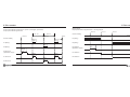
1
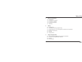
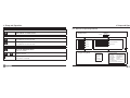
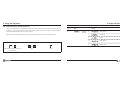
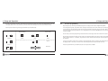
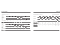
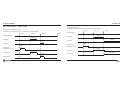
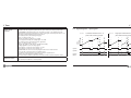
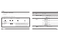
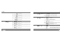
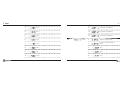
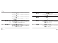
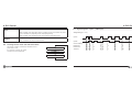
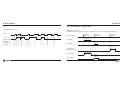
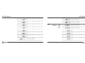
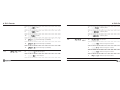
English
User Manual
Part-No. 2 772 058 englisch; 04/2010
Table of Contents
1
General Information
1.1
1.2
1.3
1.4
1.5
2
Introduction
Explanation of symbols
Limitation of Liability
Copyright protection
Warranty
7
9
10
11
11
Safety
2.1
2.2
2.3
2.4
2.5
2.6
3
7
12
Intended Use
Assembly, connecting, programming
Responsibilities of the machine/plant manufacturer and operator
Operator requirements
Hazards
Safety devices
Setup and Operation
3.1
3.2
3.3
3.4
12
13
16
17
18
20
21
Dimension Sheet / Multifunction Counter Installation
Connecting the Multifunction Counter
Display
Key functions
3
22
23
28
30
Table of Contents
3.5
3.6
3.7
3.8
3.9
3.10
3.11
3.12
Table of Contents
Overview of Operating Elements
Programming the Standard Function
Programming the Function Codes
Programming the Preset Modes
The Prescaler Programming
Programming the (User) Times
Output of Device ID
Adjusting the backlight
33
34
36
37
39
40
42
43
4
General Functions of the Multifunctional Counter
44
5
Pulse Counter
51
5.1
5.2
5.3
5.4
6
Description of Pulse Counter
Signal diagrams – counter input signals
Signal diagrams – counter output signals
Programming the counter function codes
51
53
56
60
Tachometer
6.1
6.2
6.3
7
7.1
7.2
7.3
7.4
8
9
4
75
77
78
88
Timer description
Signal diagram – timer input signals
Signal diagrams – timer output signals
Programming the timer function codes
88
91
94
94
Shift Counter
8.1
8.2
8.3
8.4
8.5
111
Shift counter description
Scroll between Total Sum and Partial Sums
Signal diagrams – shift counter input signals
Signal diagrams – shift counter output signals
Programming the shift-counter function codes
Batch Counter
111
112
113
115
116
131
9.1 Batch counter description
9.2 Signal diagrams – batch counter
9.3 Programming the batch counter function codes
75
Tachometer description
Signal diagrams - tachometer
Programming the tachometer function codes
Timer
131
133
134
10
Technical Data
150
11
Transport, Packaging, Storage
157
5
Table of Contents
General Information
1 General Information
12
Maintenance and cleaning
157
13
Trouble shooting
158
14
Spare parts
160
15
Dismantling and disposal
160
16
Model numbers
161
The multifunction counter has been designed for industrial use and for installation in machinery or industrial
plants.
17
Accessories and spare parts
162
The party responsible for the end use/application has the ultimate responsibility to ensure that the multifunction
counter is installed and set-up in accordance with the operating guidelines set forth in this manual.
1.1 Introduction
These operating instructions provide important information about the operation and handling of the multifunctional counter. To ensure safe operation it is vital that the safety information and instructions be strictly observed.
For Versacount XP models please reference the amendment 2 772 069 in addition to these instructions.
All local regulations applicable to safety and accident prevention must be adhered to for the installation and operation of this multifunction counter.
Please read these instructions before installing or operating the multifunction counter.
These operating instructions are an integral part of the product and must be maintained in the direct vicinity of
the multifunction counter or in a place that is readily accessible.
6
7
General Information
General Information
These operating instructions contain important information concerning the installation, programming and operation the multifunction counter.
1.2 Explanation of symbols
The warnings in these operating instructions are designated by symbols and words that indicate the severity of a
safety hazard.
Description of the programming sequence:
- Programming of the basic functions
- Programming of the function codes
- Programming of the user times
- Programming of the prescaler
- Programming of the presets
These warnings must be observed at all times and appropriate actions must be taken at all times to prevent accidents, damage, personal injury or death.
Danger!
This warning indicates a direct safety hazard, which may lead to serious injuries or
even death if preventative action is not taken.
Before commissioning the multifunction counter, consider locking-out functions not required for regular operation.
The executed programming functions must be documented.
Warning!
This warning indicates a possible safety hazard, which may lead to serious injuries
or even death if preventative action is not taken.
Caution!
This warning indicates a possible safety hazard, which may lead to minor damage
or injuries if preventative action is not taken.
8
9
General Information
General Information
Note!
This symbol indicates a potentially hazardous situation, which may lead to damage
to property or to the environment if preventative action is not taken.
Tips and recommendations
This symbol is used to point out to useful tips, recommendations and information
for optimal operation.
1.3 Limitation of Liability
The information contained in these operating instructions was gathered in accordance with applicable standards
and regulations.
The manufacturer shall not assume any liability for damage caused by:
The actual product may not appear exactly as illustrated in this manual.
1.4 Copyright protection
The operating instructions must be treated confidentially and used exclusively by the personnel responsible for
the setup, maintenance, repair and operation of the counter. Disclosure of these operating instructions to any
third parties is not permissible without the prior written consent of the manufacturer.
The data and information stated here, including text, drawings, images and other
illustrations, are protected by copyright laws and subject to industrial property
rights. Any misuse of such information will be subject to prosecution.
1.5 Warranty
Our standard warranty is available on our website at www.veeder-rootcounters.com.
- Non-adherence to the operating instructions
- Improper use
- Employment of unskilled or untrained personnel
- Modifications or changes to the multifunction counter
- Opening of the multifunction counter
We reserve the right to make changes or modifications to the design, specifications or options without notice.
10
11
Safety
Safety
2
Safety
2.2 Assembly, connection, programming
This section provides an overview of important consideration to ensure the safe and trouble-free operation of
your counter. Non-adherence to these instructions may result in serious injury or death.
2.1 Intended Use
The multifunction counter is built and tested in accordance with IEC/EN 61010-1, Protection Class II – Safety
Measures for Electronic Measuring Equipment. They have left the factory in a condition that is in compliance with
all safety-relevant requirements. In order to maintain this condition and ensure operational safety, the User is required to observe the safety notes and warnings in these operating instructions!
The multifunctional counter is exclusively designed and constructed for the intended use and purposes described
herein.
The multifunctional counter serves together with a corresponding sensor for the counting of pieces,
lengths, flow rates, velocities and times, as well as for the controlling and monitoring of machinery and
equipment by sending and receiving control signals.
Warning!
Safety hazards due to improper use!
Using the multifunction counter for any purposes other than those described may
cause hazardous situations.
Claims for damages resulting from any kind of misuse shall be expressly excluded.
12
Danger!
Risk of safety hazards due to incorrect/faulty assembly and connection.
•
The maximum operating voltages must not be exceeded!
•
12 – 24VDC and 24VAC multifunction counters must be operated at safety extra-low voltages (SELV) and under potential-compensated conditions in order to prevent hazardous shock.
•
An external fuse must be provided to protect the multifunction counter (see Chapter 10, Technical Data).
•
Installation and assembly shall be carried out by skilled and trained electricians only.
•
Do not connect or disconnect a multifunction counter while it is in contact with a live current. Always disconnect the main power supply before connecting or disconnecting the multifunction counter.
•
All terminals should be properly insulated to prevent accidental contact.
13
Safety
Safety
•
To prevent accidental shock or injury, ensure that live conductors are securely connected to the terminals and
properly insulated.
•
The rules and regulations set forth by the local electricity providers have to be observed.
•
Do not establish any connections with non-allocated (NC) terminals.
•
Danger!
The party responsible for the commissioning of the multifunction counter must
take precautions to ensure the safe operation of the device.
•
The party responsible for the commissioning of the multifunction counter is responsible for the preparation
of operating instructions including:
Multifunction counters may only be operated when properly installed.
•
Description of functions according to the programming of the multifunction counter;
•
If safe operation is impaired, make the multifunction counter inoperable and secure it against
inadvertent operation.
•
Description of the settings to be adjusted by the machine/plant operator;
•
Scope of applications: industrial processes and controls. Overvoltage across the terminals must be limited to
the values specified in overvoltage category II.
•
Information concerning the occupational safety requirements and possible hazards arising from the operation
of the machine/plant.
•
The installation and wiring has considerable impact on the electromagnetic properties of the multifunction
counter. Therefore, electromagnetic compatibility of the entire application must be ensured during the installation.
•
In areas presenting the risk of ESD (electrostatic discharge), use ESD-protected plugs and switches.
•
If the functions “prescaler input”, “preset input” and “key reset” are not allowed to be used by the machine/
plant operator, access to these functions must be locked. Depending on the application, non-permissible input may impair the safe operation and function.
14
15
Safety
Safety
2.3 Responsibilities of the machine/plant manufacturer and operator
•
Multifunctional counters are designed for installation and use in machines/plants. Therefore, the manufacturer
and operator of the machine/plant are subject to the legal obligations concerning occupational safety and health.
The owner shall ensure that the operation, maintenance and repair of the machine/plant is exclusively carried out by skilled and trained personnel.
2.4 Operator requirements
In particular:
Warning:
Risk of personal injury is operated by unqualified individuals!
Improper handling may cause severe personal injuries and damage to property.
•
The machine/plant manufacturer shall be obligated to ensure that all the requirements mentioned in section
2.2 be adhered to during the assembly, connection and programming.
•
The operator shall obtain all required information regarding applicable occupational safety rules. In addition,
the operator shall be obligated to prepare a risk assessment of possible hazards that may arise at the place of
operation. This risk assessment shall be documented in the form of operating instructions for the machine/
plant.
•
Actions requiring special skills must be carried out only by trained personnel as designated in these instructions.
The machine/plant manufacturer and operator are responsible for regularly checking local occupational safety
and health requirements and, its required, making appropriate revisions to the application instructions.
•
Keep unqualified/untrained personnel away from hazard areas.
•
•
The operator shall ensure that all staff members who are involved in the machine/plant operation have read
and fully understood these instructions. Moreover, the operator shall be obligated to train the operating personnel at regular intervals and inform them about any potential hazards.
16
17
Safety
Safety
The following staff qualification requirements have been defined for the various scopes of
activities:
•
Instructed personnel
These persons have been instructed by the operator with regard to the tasks assigned and the potential
hazards caused by improper handling.
•
Skilled personnel
Due to their educational and professional skills, know-how and experience, as well as their knowledge of relevant regulations, these persons are capable of executing their assigned tasks, safely and competently.
•
Skilled and trained electricians
Due to their educational and professional skills, know-how and experience, and their knowledge of electrical
codes, these persons are capable of executing electrical work safely and competently.
2.5
Hazards
Danger!
Lethal hazard of electric shock!
Any contact with live currents presents a direct lethal hazard.
Damages to the insulation or individual components present a potential lethal hazard.
• In the event of damage to the insulation, immediately disconnect the power supply and
initiate the appropriate repair work.
• All electrical work must be carried out by skilled and trained electricians.
This section indicates certain risks, which may arise as a result of improper installation or application.
• Before commencing your work on the electrical system, disconnect it from the main power supply and check that it no longer carries any live currents.
The safety information and warnings in these instructions must be observed in order to reduce the risk of hazards
or injury.
• Prior to conducting any maintenance, cleaning or repair work, disconnect the main power
supply and secure it against inadvertent engagement.
• Do not short-circuit or bypass/jump fuses.
18
19
Safety
3 Setup and Operation
2.6 Safety devices
3
Warning! Lethal hazard by non-functional or non-existent safety devices!
Safety devices must be installed to ensure operational safety.
The multifunction counter does not include any installed safety devices.
These safety devices must be installed externally.
Protect the electrical supply of the multifunction counter by means of external fuses (see Chapter 10, Technical
Data).
Whether or not additional safety devices (e.g. emergency-off buttons) have to be provided depends on the application and construction of the machine or plant.
The machine/plant manufacturer shall be responsible for providing such additional safety devices in according
with their own risk assessment and applicable local laws and regulations.
20
Setup and Operation
1
Display
2
Operating keys
3
Flat gasket
4
Bracket
5
Enclosure
6
pply;
Plug for DC or sensor supply;
utputs
Electronic inputs and outputs
7
Connection terminal AC supply
and relay contacts
8
Circuit diagram
21
3 Setup and Operation
3 Setup and Operation
3.1 Dimension Sheet / Installation of Multifunction Counter
3.2 Connecting the Multifunction Counter
VDC 2 relays / 2 transistors
22
VAC 2 relays / 2 transistors
23
3 Setup and Operation
3 Setup and Operation
VDC 1 relays / 2 transistors
VAC transformer 1 Relays / 2 transistors
24
VDC 2 transistors
VAC 2 transistors
25
3 Setup and Operation
3 Setup and Operation
The plug has to be disconnected from
the counter before the cables are
fastened by means of screws or
screw-type terminals.
Do not connect the encoder to a
direct current line voltage without
protective circuit for EMC. For cable
lenths > 30 m/100 ft a protective
circuit is always required!
When programming the input level to
TTL an additional protective circuit is
required.
VAC switching power supply 2 relays / 2 transistors
VAC switching power supply 1 relay / 2 transistors
26
We recommend installation in a metal,
grounded panel.
VAC switching power supply 2 transistors
27
3 Setup and Operation
3 Setup and Operation
For DC-Versions:
When switching on the device in PNP-Mode, a short signal is applied to inputs A,B,C and the application input.
Timer: Timer running
To suppress the pulse in TTL-Mode, each input should be connected to a 10 kOhm resistor and the OV.
When switching on the device a short signal is applied to the application output.
To suppress this pulses connect a resistor of 10 kOhm / 0.225 W to the 0 V and the application-output.
3.3 Display
After powering on, all characters are illuminated for approx. 2 seconds; then the display changes over to the Display or Programming Mode.
The display is available in four different versions:
Transflective Positive: black figures on background
Transmissive Negative: white figures on black background
Transmissive red: red figures on black background
Transmissive green: green figures on black background
28
Prescaler
29
3 Setup and Operation
3 Setup and Operation
3.4 Key functions
During the Programming of Function Codes
Enter - Key
UP - Key
DOWN - Key
SHIFT - Key
+
Display function code
Switches between function code text and function code number
During Operation
Programming
If pressed together with POWER ON (keep keys pressed and switch on the device)
+
Sets reset
+
Selects standard functions
+
Sets preset 0
+
Sets function codes
+
Sets preset 1
+
Selects ID data
+
Sets preset 2
+
Sets User Times
+
Sets prescaler
(Model number, manufacturing date, serial number,...)
30
31
3 Setup and Operation
3 Setup and Operation
3.5 Overview of Operating Elements
Additional function for shift and batch counters
Switches between total sum and partial sums and/or count value
and totalizer or batch counter
Display Mode
123456
Reset
up + dn
0
Additional functions for timers
Timer start
(If enabled with function code F15)
E + up
= Preset 2
E + up at power on
= Standard function
Timer stop
E + dn
= Preset 1
E + dn at power on
= Function Parameter
E + shift
= Preset 0
up + shift at power on
up + shift
= Prescaler
(If enabled with function code F15)
Additional functions backlight versions
= Signal times
E
Go to the adjustment menu
(hold for 5 seconds)
+
Adjust the intensity
Programming Mode
(brighter or darker)
Save and go back to display mode
(press within 15 seconds)
32
Standard Funct.
Function parameters:
Pulse counter
Tachometer
Timer
Shift counter
Batch counter
Operat. Mode
Count frequency
Decimal point
Reset Behavior
Set/Reset-Mode Output Memory
Display-Mode
Keylock
Output signals
npn/pnp selection
Applic. Input/Output
+ many other function parameters
33
3 Setup and Operation
3 Setup and Operation
3.6 Programming the Standard Function
The device described here is a multifunction counter, which can be programmed for a variety of functions and applications, i.e. pulse counter, tachometer, timer, shift counter or batch counter. The first step is to set the standard
function (the default factory setting is “pulse counter”).
Now continue with the programming of the function codes (Chapters 5-9) or User Times (Chapter 3.10)
Enter Programming mode
+
Keep pressed and switch Power on simultaneously
Change function setting:
Function
code
Fn
Display
Row 1
Display
Row 2
Function
No.
Sets
Standard
Function
0*
Pulse Counter
1
Tachometer
2
Timer
3
Shift Counter
4
Batch Counter
Save, return to counter operation
or
press
34
press
35
3 Setup and Operation
3 Setup and Operation
3.7 Programming the Function Codes
The function codes (system parameters) are used to program the function of the inputs and outputs and the device itself. The selection options are described in detail in Chapters 5 to 9.
Attention: With each change among text and numeric display, the currently
selected function code will return to the factory default setting and may have to
be readjusted.
The factory default setting is designated with an asterix *.
Enter Programming mode
+
Keep pressed and switch
Power on simultaneously
Change function setting
Save and change to next
function code
Save and change to
counter operation
3.8 Programming the Preset Values
By simultaneously pressing the E + Up, E + Down or E + Shift key you can change to the Preset programming
mode:
or
press
press
Change between Text Display and Numerical Display
press
+
In the function code Programming Mode, the first row shows the name of the function code in the form of text
(7-segment display). The second row shows the selectable option in a text form. By simultaneously pressing the
Up and Down buttons, the display in the first row changes to a numerical display; after pressing these buttons
once again, the display in the second row also changes to a numerical display. Pressing these buttons for a third
time reverts both rows back to the text display.
36
Use the shift key in the programming mode to change a setting position. The selected position will start to flash.
Use the shift key again to move one position to the right. Then use the UP or Down key to increment or decrement the position by 1.
Rule for the 6th position: The change from 9 to 0 or 0 to 9 is indicated by a changing prefix.
Use the E key to leave the programming mode and return to the display mode. Your entries will be saved.
On leaving the programming mode, the presets are tested for attainability and recalculated, if necessary, because
not all the values may be attained at a prescaler value of >1. The presetting is then rounded to the closest attainable value.
37
3 Setup and Operation
3 Setup and Operation
If no key is pressed for more than 16 seconds in the programming mode, the counter will automatically return to
the display mode. In this case, however, no entries will be saved except the last value saved with the E-key.
Set the preset value to 0 by pressing Up and Down keys simultaneously.
Enter Programming mode
Select a position:
(starts flashing)
Set position:
Save and return to
display mode
3.9
Prescaler programming
By pressing the Up + Shift keys simultaneously you can change to the Prescaler Programming Mode.
In the Programming mode, the position to be changed is selected by means of the shift key. The selected position
will start flashing. Use the shift key again to move by one position to the right. Then use the UP or Down key to
increment or decrement the position by 1. It is not possible to save a value of 00.0000. In this case the system
will save 01.0000.
Use the E key to leave the programming mode and return to the display mode. Your entries will be saved.
+
Preset 2
or
press
press
+
+
press
Zero in
Preset 1
On leaving the programming mode, all the presets are recalculated because not all the values may be attained
with a prescaler value of >1. Therefore, the presets have to be checked and corrected as necessary after setting
the prescaler.
If no key is pressed for more than 16 seconds in the programming mode, the counter will automatically return to
the display mode. In this case, no entries will be saved except the last value saved with the E-key.
Press the Up and Down keys simultaneously to set the prescaler to 01.0000.
Set Preset
+
Preset 0
38
39
3 Setup and Operation
Enter Programming mode
3 Setup and Operation
Select a position:
(starts flashing)
Set position
+
press
+
Save and return to
display mode
Enter Programming mode
or
press
press
set to 01.0000
Set position
Save and go to the next
user setting; after user 3,
return to display mode
+
or
press
Set prescaler
Keep pressed and switch
Power on simultaneously
Function
code
3.10 Programming the user times
Fn
For programming the signal time for monostable (timed) output signals, 9 fixed signal times between 0.02 s and
10 s are available. In addition, three different signal times between 0.01 s and 599.99 s can be set by the user. The
outputs are deactivated if the setting is 0.00 s.
40
Select a position:
(starts flashing)
Display
Row 1
press
press
Display
Row 2
Function
No.
Sets the
Signal
Times
0*
Signal time 1
1
Signal time 2
2
Signal time 3
41
press
3 Setup and Operation
3 Setup and Operation
3.11 Output of Device ID
3.12 Adjusting the intensity of the backlight
This function is used to retrieve Device ID data, e.g. model numbers and various manufacturing information
Enter Output mode
Change to the next output
Return to counter operation
press
press
For counters that come with a backlight you have the ability to adjust the intensity.
To adjust the backlight, press SHIFT for more than 5 seconds. The display then shows:
+
Keep pressed and switch Power on
simultaneously
Display row 1
By pressing the UP or DOWN key the display gets brighter or darker.
Model number
If the E-button is pressed within 15 seconds, you go back to the normal counter display and the adjusted setting
is saved. If the E-button is not pressed within 15 seconds, you will go back automatically to the normal counter
menu without saving any changes.
Manufacturing date
Go to the adjustment menu
Display row 2
Adjust intensity
Save and go back to
display mode
Serial number
or
Software number
Software release
42
press > 5 s
press
43
press within 15 s
4 General Functions of the Multifunction Counter
4 General Functions of the Multifunction Counter
The following description is applicable for all com settings. Special functions and configurations can be found in
the appropriate chapters of this manual.
Factory setting
(Defaults)
The Prescaler is used, for example, to convert counter pulses into meaningful units, to adapt
the units of measurements (e.g. cm-pulses to inch-pulses), or to compensate for worn out
measuring wheels.
Sets all the function codes to the default factory settings,
i.e. all codes designated with *.
Prescaler (pulse mete- The “Prescaler” is a multiplier. Each input pulse is multiplied by the adjustment factor. The
display shows integers only. After a reset the counter is completely reset to 0; this also inring factor):
cludes the non-visible value of < 1.
[PSC]
At a prescaler of >1 not all the values are selectable. If invalid Preset values are selected,
the counter will round them up to the next possible value.
Example: PSC 5 cannot select (reach) Preset value 7. In this case, the counter automatically
changes the Preset value to 10.
If the Prescaler is changed, this may also affect the Preset values, which would have to be
changed accordingly.
Formula: PSC = Desired/nominal display / number of pulses
Example: Flowmeter 173 pulses per 100 liters; display in liters
PSC = 100 / 173 = 0.5780
Example: 1 pulse per cm; display in inch
PSC = 1 / 2.54 = 0.3937
Attention: This is only valid for counters and tachometers.
For timers please refer to chapter 7.
2nd row display:
The display of the 2nd row can be programmed as follows:
Preset 2 (P2), Preset 1 (P1), Preset 0 (P0), Prescaler, Batch counter, totalizer or partial sums
(shift counter)
Counter and control
inputs:
The counter is fitted with 3 counter and control inputs and an application input (see below).
These inputs are assigned various counter or control functions by means of function code
settings.
Input logic:
The input logic can be programmed to NPN or PNP, each at the 8V-level or TTL level; see
Chapter 10 for the switching threshold.
Adjusting range 0.0001 to 99.9999
44
45
4 General Functions of the Multifunction Counter
Reset/Set:
Manual setting via keys (lockable)
Electronic setting via control input (and/or application input)
Automatic programming after reaching the main Preselection
Programmable Power-On Reset
4 General Functions of the Multifunction Counter
Static/dynamic reset:
Static reset:
Dynamic reset:
Reset over the entire pulse width of the reset pulse
Reset via the active edge; thereafter, counter operation is possible
independently of the pulse width of the reset pulse.
Exception: Tachometers do not have a reset/set function
Depending on the function code the counter is:
1) Reset: reset to 0
P2 is the main Preset (preselect) value
During unidirectional counting the counter will add up.
or
2) Set: reset to P2
Signal 2 at 0 - Output 2 at 0
During unidirectional counting the counter will subtract.
Teach input:
Using the Teach Input (application input) the counter status is imported in Preset 2.
Decimal Point:
The decimal point is only an optical reading assistence on the display and does not change
the value. For example, for a value of 1 pulse per cm, the setting 0.00 makes it easier to
read the value in m and cm.
Exception: This does not apply to tachometers and timers.
Please refer to Chapters 6 and 7.
For time counting, batch counting or shift counting, it is possible to reset partial sums or
the total sum, batch counter or second totalizer individually or at the same time via
the application input.
Independently the counter can be reset to Preset value 0 via the application input (see
below).
Exception: Tachometers do not have a reset/set function
46
47
4 General description of the multifunction counter
Input damping
(Attenuation)
The inputs A and B are limited to 60 kHz.
The Application Input is limited to 6 kHz.
4 General Functions of the Multifunction Counter
Signals:
Following maximum input frequencies are not to be exceeded:
Quadrature x1: A and B each 30 kHz (TTL 15 kHz)
Quadrature x2: A and B each 30 kHz (TTL 15 kHz)
Quadrature x4: A and B each 15 kHz (TTL 15 kHz)
Unidirectional counting and directional input: Input A 60 kHz (TTL 15 kHz)
Differential counting, summation (totalizing): Input A + B 60 kHz (TTL 15 kHz)
If a signal is active, this will be shown on the LCD display.
Optionally, the multifunctional counter can be set to have the display flash if one or all the
preset values are active.
This is also valid for Preset 0 (if no output has been assigned).
Signal time:
When the application input is used as an additional count input, the above mentioned input
frequencies have to be reduced by the frequency of the application input.
If mechanical contacts are triggered (i.e. relays, switches, Reed contacts, etc.), the input frequency has to be damped (attenuated) to 30 Hz, so as to filter out bounce pulses.
If damping to 30 Hz is selected, all inputs can be used at 30 Hz.
To reach these values the amplitude thresholds are to be held.
(See technical data - chapter 10)
48
P1 and P2 are available as relay changeover contacts and electronic output signals (PNP).
P0 is available as an electronic output signal across the application output (PNP).
Signals active
on/off
Application input/output:
1) bistable (latching): Cleared by electronic or manual reset.
P 0 + P 1= bistable (latching) – additionally cleared by signal 2
Attention: Signal 2 must not be bistable (latching) for automatic reset.
2) monostable (timed): Up to 9 fixed signal times are available between 0.02s and 10s. In
addition, user times can be programmed between 0.01s to 599.99s.
3) Range signals: active as long as the counter reading is within the adjusted range.
During normal operation the relay is energized if the signal is active.
This behavior can also be inverted (also applicable to the transistor outputs).
Depending on the standard function, up to 11 (eleven) functions can be assigned to the application input/output. Note, however, that only one of these functions can be selected.
Further details are given in the Function Code Section (5.4).
49
4 General Functions of the Multifunction Counter
Application – Set
to preset 0
Programs the application input to act as a Set Input. The counter is set to Preset 0, independently of the reset via input C or the keyboard.
This function is not available for tachometers.
Application
keylock:
5 Pulse counter
5.1 Description of the Pulse Counter
(Supplementing the General Functions in Chapter 4)
Counter mode
The following counter modes can be selected:
Unidirectional counting, adding or subtracting;
Unidirectional counting with directional input;
Differential counting, summation (totalizing) or
Quadrature x1; x2 or x4.
Output signals mode
of operation:
1) coincidence signal: The counter operates in the coincidence mode, i.e. output signals are
activated after reaching the Preset value for the programmed period of time.
All keyboard functions can be locked individually
(Reset, P 0, P 1, P 2, Prescaler)
Lock mode: release after 10s, complete keylock or
keylock depending on keylock input (application input)
After setting up the system, lock all the keyboard functions you do not want to be
changed by the user.
2) Trail: P2 and P0 are under coincidence operation; they operate as described in item A.
P1 is the trail. P1 is not absolute to 0, but relative to P2.
If the setting is F8=1, the following will apply:
Signal 1 is returned at P2 – P1
Example: P2=1000, P1=200, Signal 1 at 800;
If P1 is negative: P2=1000, P1=(-200), Signal 1 at 1200
If the setting is F8=2, the following will be applicable:
Signal 1 is returned at P2 + and – P1
(Example: P2=1000, P1=200, Signal 1 at 800 or/and 1200)
3) range signal: P1 and P2 are range signals:
Signal 1 is active at a counter reading < P1 and
Signal 2 is active at a counter reading > P2
50
51
5 Pulse counter
Intermediate cut:
Additional totalizer
(summation counter)
Prescaler Output
PSC-out:
5 Pulse counter
Depending on the application it may become necessary to isolate the main signal during the
reset, e.g. when the first material lengths or certain lengths showing material defects have
to be cut on length-cutting systems.
The additional totalizer sums up all values even if the main counter is continually reset. The
shift key can be used to switch between the counter reading and the total sum. The totalizer can only be reset manually.
To do this, select the total sum from the first row; then press the reset keys.
The prescaler output is an application output.
With each increase of the counter reading the number of output pulses corresponds to the
respective number of increments.
The pulse length of the prescaler output corresponds to a frequency of 500 Hz.
When using the prescaler output the max. count frequency is:
F max = 500 / PSC.
So it is possible that the maximum input frequency can not be reached.
Application counter
input add / sub
The application input may be assigned to the Count Up or Count Down function.
This is a counter input, which is available in addition to the counter mode adjusted with F1.
Application
Latch/Reset
Latch/Reset is an application input. If the counter is reset via the application input, the
counter reading is held constant. The counter continues to remain fully functional and operates in the background mode. During the next reset the current (updated) value will be
shown on the display.
5.2 Signal diagrams input signals (PNP-Logic)
Unidirectional counting (F1 = C G r) = 0
Input A
Counter input
Input B
Gate
Input C
Reset
Counter reading
2
3
3
4
5
0
1
2
3
2
3
4
0
1
Directional input(F1= C d r) = 1
Input A
Counter input
Input B
Directional input
Input C
Reset
Counter reading
52
1
1
53
5 Pulse counter
5 Pulse counter
Differential input (F1= A S r) = 3
Phase discriminator (F1 = QUAd r) = 6
Input A
Adding
Channel A
Change of rotating direction
Input B
Subtracting
Channel B
Input C
Reset
Counter reading
1
2
3
2
1
2
0
1
Input C
Reset (dynamic)
Counter reading single 1
2
3
4
5
4
0
-1
Evaluat. (F2=0)
Counter reading double 1
2
3
4
5
6
7
8
9
8
7
0
-1
-2
Evaluat. (F2=1)
Counter reading quad. 1 2 3 4 5 6 7 8 9 10 11 12 13 14 15 16 17 17 16 15 14 13 0 -1 -2 -3 -4
Evaluat. (F2=2)
Summation (totalizer) input (F1= A A r) = 5
Input A
Adding
Input B
Adding
Input C
Reset
Counter reading
1
2
4
5
54
6
7
0
1
55
5 Pulse counter
5 Pulse counter
5.3 Signal diagrams - Output signals
Output signals latching
Coincidence signal time P0 (F10) timed P1 (F11), P2 (F12) latching
Output signals monostable (timed)
Coincidence signals P0 (F10), P1 (F11), P2 (F12) monostable (timed)
Preset 0
Preset 1
Preset 2
Reset
Counter reading
Preset 0
Preset 1
Preset 2
Reset
Counter reading
latching
P1 (Relay)
Signal time
P1 (Relay)
latching
Signal
time
P2 (Relay)
P2 (Relay)
P0 electronic
(Application output)
P0 electronic
(Application output)
Signal
time
Signal
time
latching
P1 electronic
Signal time
P1 electronic
latching
Signal
time
P2 electronic
P2 electronic
56
57
5 Pulse counter
5 Pulse counter
Trail Preset
P0 (F10) Coincidence signal timed, P1 (F8+F11) trail signal, symmetrical,
P2 (F12) Coincidence signal timed
P2 - P1
Preset 0
Counter reading
Range signals
P0 (F10) Coincidence signal timed P1 + P2 range signal
Preset 0
P2 + P1
Preset 2
Signal
time
Reset
Signal
time
P1 (Relay)
P1 (Relay)
P2 (Relay)
Signal
time
P2 (Relay)
P0 electronic
(Application output)
Preset 1
Counter reading
P0 electronc
(Application output)
Signal
time
Signal
time
P1 electronic
Signal
time
Signal
time
P1 electronic
P2 electronic
Signal
time
P2 electronic
58
59
Preset 2
Reset
5 Pulse counter
5 Pulse counter
5.4 Programming the counter function codes
Enter Programming
mode
+
Function
code
Change function setting
Save and change to
next function
Return to display mode
F0
Display
Row 1
Function
Factory
Setting
(Defaults)
No.
Display
Row 2
0*
No Function
1
All Function Codes are set to
the default values marked with *
or
Keep pressed and
simultaneously
turn Power On
press
Alternative display
of function codes
+
press
press
The function codes are displayed as text in row 1.
By pressing both keys simultaneously you can change to
the numerical display (F 0 to F 35). After pressing these
keys once again the number of the selectable options will
be displayed in addition. This setting will be stored.
60
F1
Counter
Mode
Input A
Input B
Input C
Count. inpt.
Gate/ Inhibit
Reset
1
Count.inpt.
Direction.
Input
Reset
2
Count.inpt.
Direction.
Input
Gate/ Inhibit
3
Adding
Subtracting
Reset
4
Adding
Subtracting
Gate/ Inhibit
0*
61
5 Pulse counter
F2
F3
5 Pulse counter
5
Adding
Adding
Reset
6
Channel A
Channel B
Reset
7
Channel A
Channel B
Gate/ Inhibit
Edge Evalution
0*
Single evaluation
/Quadrat.
evaluation
1
PNP/NPNLogic
3
PNP TTL-Level
0
30 Hz damping (e.g. for mechanical contacts)
1*
F max. (see chapters 4 and 10)
0*
Reset to 0
Double evaluation
1
Automatic reset to 0 after reaching Preset 2
2
Quadruple evaluation
2
Set to Preset 2
0
NPN 8V-Level
3
Automatic selection of Preset 2 after reaching 0
1*
PNP 8-V Level
0*
Static reset (reset as long as the signal is applied)
2
NPN TTL-Level
F4
F5
F6
62
Inputdamping
(Attenuation)
Set / Reset- Mode
dynam./
static
Reset
63
5 Pulse counter
F8
F9
F10
5 Pulse counter
Mode
Preset 1
Output
signal
Signal
time P0
1
Dynamic Reset (ready to count after reset (even
if reset signal is applied for a longer time)
2
0.02 s
0*
P1 normal preset; absolute to the counter
reading (coincidence signal)
3
0.05 s
1
P1 as a trail preset with prefix (relative to P2)
4*
0.10 s
2
P1 as a trail preset symmetrical (relative to P2)
5
0.20 s
3
P1 and P2 as a range signal
(Signal 1 < P1, Signal 2 > P2)
6
0.50 s
o*
Active On
7
1.00 s
1
Active Off
8
2.00 s
0
Disabled / No output signal
9
5.00 s
1
Latching, reset with Preset 2 or Reset
10
10.00 s
64
65
5 Pulse counter
F11
5 Pulse counter
Signal
time P 1
11
User setting 1 (0-599,99 s)
6
0.50 s
12
User setting (0-599,99 s)
7
1.00 s
13
User setting 3 (0-599,99 s)
8
2.00 s
0
Disabled / No output signal
9
5.00 s
1
Latching; with Preset 2 or Reset
10
10.00 s
2
0.02 s
11
User setting 1 (0-599.99 s)
3
0.05 s
12
User setting 2 (0-599.99 s)
4*
0.10 s
13
User setting 3 (0-599.99 s)
5
0.20 s
0
Disabled / No Output signal
66
F12
Signal
time P2
67
5 Pulse counter
5 Pulse counter
1
Latching; Reset
Cannot be used in conjunction with automatic
Reset
2
0.02 s
3
0.05 s
4*
0.10 s
5
0.20 s
6
0.50 s
7
1.00 s
8
2.00 s
9
5.00 s
F13
68
Decimal
point
10
10.00 s
11
User setting 1 (0-599.99 s)
12
User setting 2 (0-599.99 s)
13
User setting 3 (0-599.99 s)
0*
No decimal point
1
1 decimal place
2
2 decimal places
3
3 decimal places
4
4 decimal places
69
5 Pulse counter
F14
F15
5 Pulse counter
Display
flashes
2nd row
display
0*
No flashing
1
Flashes as long as P0 is active
2
Flashes as long as P1 is active
3
Flashes as long as P2 is active
4
Flashes as long as any preset is active
0
Preset 0
1
Preset 1
2*
Preset 2
3
Prescaler
70
F16
F17
F18
F19
Output at
Reset (Interm.
Cut
Power On
(Reset)
Output
signal
Memory
Addtl.
Totalizer
4
Totalizer
0*
Do not activate Preset 2 during Reset
1
Activate Preset 2 during Reset
0*
Restore counter value
1
Reset at Power On
0
Restart signal time after power failure
output switches
1*
Do not restart signal time after power failure
0
Enabled
1*
Disabled
71
5 Pulse counter
F22
5 Pulse counter
Applica.
Input/
Output
0
Prescaler output
9
Teach input
(count value becomes P2)
1
Output Preset 0
10
Set input (Set to Preset 0)
2
Directional output
11
Latch and Reset
(Save display at Reset)
3*
Counter input - adding
4
Counter input – subtracting
5
Reset input
6
Gate/Inhibit input
7
Keylock input
8
Hold input (display lock)
72
F24 - F27 are applicable to multifunction counters with a USB or Ethernet
interface. Consult the supplement included with those versions.
F30
F31
Lock Reset
key
Lock
Preset 0
0*
Enable keyboard reset
1
Keyboard reset locked/delayed
0*
P0 Setting enabled
1
P0 Setting locked / delayed
73
5 Pulse counter
6 Tachometer
6 Tachometer
F32
Lock
Preset 1
0*
P1 Setting enabled
6.1 Tachometer Description
(Supplementing the General Functions in Chapter 4)
P1 Setting locked / delayed
1
F33
F34
F35
Lock
Preset 2
Lock
Prescaler
setting
Lock
Mode
Operation:
0*
P2 Setting enabled
1
P2 Setting locked / delayed
0*
PSC setting enabled
1
PSC Setting locked / delayed
0*
10 seconds delay
1
Completely locked
2
Lock depends on keylock input
74
Tachometer
Mode of Operation:
Decimal point
A tachometer measures the period (PNP: time from one rising edge to the next one); NPN:
time period from a falling edge to the next one), and converts and displays this time in
1/sec or 1/min.
The following modes of tachometer operation can be selected:
Unidirectional counting;
Unidirectional counting with directional input;
Differential counting, summation (totalizing);
Quadrature x1; x2 or x4;Indication of ratio A/B and
Indication of percentage (A-B) /A in %
Tachometer mode of operation 0-4 (function code F1)
The decimal point only serves for better legibility and does not change the value.
Tachometer mode of operation 5 & 6 (function code F1)
The decimal point is included in the calculation and increases the resolution.
75
6 Tachometer
The tachometer uses the following limit values:
P 1 and P2 are limit (range) signals
Output-Signal 1 is active at the displayed value of < P1 and
Output-Signal 2 is active at the displayed value of > P2
Output-Signal 0 is active at the displayed value of > P0; (application output)
6.2 Signal diagram - Output signals
Input frequency
P0
P2
Display unit:
Programmable: 1/sec or 1/min
Using the setting 1/min and prescaler 60 the display will show 1/hour.
Min. input frequency:
Programmable 1 Hz or 0.1 Hz.
If two edges do not occur within 1 s or respectively, 10s,
a value of 0 will be displayed.
P1
Startup
suppression:
Programmable Yes/No
During the startup the lower limit signal is suppressed until the lower limit value is exceeded for the first time.
P1 (Relay)
Frequency Hz
Output signals
Mode of operation:
6 Tachometer
Output signals
P2 (Relay)
The startup suppression will become active again, if the minimum frequency is fallen below.
P0 electronic
(Application output)
P1 electronic
P2 electronic
76
77
6 Tachometer
6 Tachometer
6.3 Programming the tachometer function codes
Enter Programming
mode
Change function setting
+
or
Keep pressed and
simultaneously turn
Power On
Alternative display of
Function code:
Save and change to
next function
press
+
Funktion
code
press
Return to display mode
F0
Display
Row 2
Function
No.
Factory
Setting
(Defaults)
0*
No function
1
All function codes are set to the values marked
with *
press
The function codes are displayed as text in row 1.
By pressing both keys simultaneously you can change to
the numerical display (F 0 to F 35). After pressing these
keys once again the number of the selectable options will
be displayed in addition. This setting will be stored.
78
Display
Row 1
F1
Tacho
mode of
operation
Input A
Input B
Input C
0*
Counter input
Gate/Inhibit
Hold (Display
memory)
1
Count input
Direct. input
Hold (Display
memory)
2
Adding
subtracting
Hold (Display
memory)
3
Adding
Adding
Hold (Display
memory)
79
6 Tachometer
F2
F3
6 Tachometer
Edge
Evaluation/
Quadrat.
evaluation
PNP/
NPNLogic
Hold (Display
memory)
2
NPN TTL-Level
Channel A / Channel B
Hold (Display
memory)
3
PNP TTL-Level
6
(A-B) / A in %
(Difference in % of A)
Hold (Display
memory)
0
30 Hz attenuation (e.g. for
mechanical contacts)
0*
Single evaluation
1*
F max. (see chapter 4 und 10)
1
Dual evaluation
0*
Pulse per second (1/sec)
2
Quadruple evaluation
1
Pulse per minute (1/min)
0
NPN 8 V-Level
0*
1 Hz
(if no further pulse is received after 1s, the display will return to 0)
1*
PNP 8 V-Level
1
0,1 Hz
(if no further pulse is received after 1s, the display will return to 0)
4
Channel A
5
80
Channel B
F4
F5
F6
Input
damping
(Attenuat)
Display
Unit
Min.
Input
frequency
81
6 Tachometer
F7
F9
F10
F11
6 Tachometer
Startupsuppress.
Output
signal
P0
Addtl.
Upper
limit
P1
Lower
limit
0
With startup suppression
1*
Without startup suppression
0*
Active On
1
P2 Upper
limit
0*
Disabled / no Output signal
1
Range signal > P2
0*
No decimal point
Active Off
1
1 Decimal place
0*
Disabled / no Output signal
2
2 Decimal places
1
Additional range signal > P0
3
3 Decimal places
0*
Disabled / no Output signal
4
4 Decimal places
1
Range signal < P1
0*
Do not flash
82
F12
F13
F14
Decimal
place
Display
flashes
83
6 Tachometer
F15
6 Tachometer
2nd row
display
Application
Input/
Output
0
Output Preset 0
Flashes as long as P1 active
1
Directional output
3
Flashes as long as P2 active
2*
Count input adding, or
2nd count input A
4
Flashes if any preset is active
3
Count input subtracting, or
2nd counter input B
0
Preset 0
4
Gate/Inhibit Input
1
Preset 1
5
Hold-Input (display memory)
2*
Preset 2
6
Teach Input
(count value becomes P2)
3
Prescaler
7
Keylock-Input
1
Flashes as long as P0 active
2
84
F22
85
6 Tachometer
6 Tachometer
F24 - F27 are applicable to multifunction counters with a USB or Ethernet
interface. Consult supplement included with those versions.
F31
F32
F33
Lock Preset 0 Setting
Lock Preset 1 Setting
Lock Preset 2 Setting
F34
Lock
Prescaler
Setting
0*
PSC Setting enabled
1
PSC Setting locked / delayed
0*
10 seconds delay
0*
P0 Setting enabled
1
P0 Setting locked / delayed
0*
P1 Setting enabled
1
Completely locked
1
P1 Setting locked / delayed
2
Lock mode depends on Keylock Input
0*
P2 Setting enabled
1
P2 Setting locked / delayed
86
F35
Lock
Mode
87
7 Timer
7 Timer
7 Timer
Prescaler:
7.1 Timer Description
(Supplementing the General Functions in Chapter 4)
Function:
The timer counts seconds, minutes or hours.
Depending on the resolution (see below) the smallest units to be recorded are 0.1 ms.
Combined with the prescaler (see below), quantities can be measured as a function of time.
Time formats:
4 time formats are available:
Seconds, minutes, hours and HH:MM:SS
Resolution:
By shifting the decimal place, a resolution of up to 4 decimal places can be programmed;
the smallest resolution is 0.1 ms.
Timer mode of
operation:
The time format “seconds with four decimal places” shows 0.1 milliseconds.
The time format “seconds with three decimal places” shows milliseconds.
The time format “minutes with two decimal places” shows 1/100 minutes.
Manual Start / Stop
via keyboard:
88
During the timer operation the prescaler has to be disabled or set to 01.0000.
The prescaler can be used to record quantities, provided that the quantity per time unit is
known and constant.
Example: A volume of 3 liters per second is supplied.
Settings: Time format “seconds”, prescaler 3.0000
Display: Supplied volume in liters as a function of time.
The prescaler cannot be used with the time format HH:MM:SS
as it is not applicable in this application.
The following modes of timer operation can be selected:
Cumulative measurement following the pulse-width measuring principle (Cumulative
measurement as long as input A is active)
Cumulative measurement following the cycle-duration principle
(Cumulative measurement from rising edge Input A to falling edge of Input A)
Cumulative measurement A=Run, B=Stop (cumulative measurement from rising edge Input A to rising edge Input B)
Single-pulse measurement following the pulse-width measurement principle (Measure
as long as Input A is active)
Single-pulse measurement following the cycle-duration principle (Measurement from rising edge Input A to rising edge of Input A)
Single-pulse measurement A=Run, B=Stop (Cumulative measurement from rising edge
Input A to rising edge Input B)
The Start / Stop function can be set via the keyboard.
Start: Press the UP button for 0.5s
Stop: Press the DOWN button.
89
7 Timer
Additional totalizer
A) coincidence signal: The timer operates in the “coincidence” mode, i.e. the output signals
are enabled for the programmed period of time after reaching the selected preset value
B) trail signal: P2 and P0 operate in the “coincidence” mode, i.e. the output signals are
enabled for the programmed period of time when reaching the selected preset value. P1 is a
trail preset and not absolute to 0, but relative to P2.
If the setting is F8=1, the following will apply:
Signal 1 is returned at P2 – P1
Example: P2=1000, P1=200, Signal 1 at 800;
If P1 is negative: P2=1000, P1=(-200), Signal 1 at 1200
If the setting is F8=2, the following will be applicable:
Signal 1 is returned at P2 + und – P1
(Example: P2=1000, P1=200, Signal 1 at 800 or/and 1200)
C) range signal: P1 and 2 are range signals:
Output-Signal 1 is active at timer reading < P1 and
Output-Signal 2 is active at timer reading > P2
D) batch mode: The timer can also be programmed to act as a batch counter.
In this case, P2= main preset value; P1= Batch preset.
In the Batch mode of operation, only positive entries are possible for P1;
negative entries will be stored as positive values.
This mode is ideal to default a process time and the number of process sequences (runs).
7.2 Signal Diagrams - Input signals
F7 = 0
Cumulative Measurement acc. to
pulse-width measuring principle
Time
Display
Output signals –
Function:
7 Timer
Input A
Input B
Input C
Reset
The additional totalizer is used to sum up all the times (even after repeated resetting of the
main counter). The totalizer is reset separately.
90
91
F7 = 3
Single-pulse Measurement acc. to
pulse-width measuring principle
7 Timer
7 Timer
Cumulative measurement acc. to
cycle-duration measuring principle
F7 = 4
Cumulative measurement acc. to
cycle-duration measuring principle
F7 = 2
Cumulative measurement acc. to
A = Run, B = Stop
F7 = 5
Cumulative measurement acc. to
A = Run, B = Stop
Input A
Input B
Input B
Input C
Reset
Input C
Reset
92
93
Stop
Start
Stop
Start
Stop
Start
Stop
Start
Stop
Start
Stop
Stop
Stop
Start
Start
Stop
Start
Input A
Start
Stop
Start
Stop
Start
Stop
Start
Time
Display
Time
Display
F7 = 1
7 Timer
7 Timer
7.3 Signal Diagrams - Output signals
The output signals of the timer can be derived from the pulse counter (see 5.3) or, respectively, batch counter (see
9.2) functions.
Function
code
F0
7.4 Programming the Timer Function Codes
Enter Programming
mode
Change function
setting
Save and change to
next function
Keep pressed and
simultaneously turn
Power On
Alternative display of
function codes
Function
Factory
Setting
(Defaults)
No.
Display
Row 2
0*
No function
1
All function codes are set to the values marked
with *
0*
Seconds
1
Minutes
2
Hours
3
HH:MM:SS
0*
No decimal point
Return to display mode
F1
+
Display
Row 1
Time unit
oder
press
+
press
press
The function codes are displayed as text in row 1.
By pressing both keys simultaneously you can change to
the numerical display (F 0 to F 35). After pressing these
keys once again the number of the selectable options will
be displayed in addition. This setting will be stored.
F2
94
Resolution
95
7 Timer
F3
7 Timer
PNP/NPNLogic
Input
(Attenuat)
0
30 Hz damping (attenuation)
(e.g. for mechanical contacts)
1*
F max. (see chapter 4 and 10)
0*
Reset to 0
4 decimal places
1
Automatic reset to 0
after reaching Preset 2
0
NPN 8 V-Level
2
Set to Preset 2
1*
PNP 8 V-Level
3
Automatically sets to Preset 2
after reaching 0.
2
NPN TTL-Level
0*
Static Reset (as long as the signal is applied)
3
PNP TTL-Level
1
Dynamic Reset (ready for operation, even if reset
signal has been applied for a longer time)
1
1 decimal place
2
2 decimal places
3
3 decimal places
4
96
F4
F5
F6
Set / Reset- Mode
dynam/
static
Reset
97
7 Timer
F7
F8
7 Timer
TimerMode of
Operation
Mode
Preset 1
0
Cumulative measurement - pulse-width (counts
as long as Input A is active)
1
P1 is a trail preset with prefix (relative to P2)
1*
Cumulative measurement – cycle duration
(counts from rising edge of start signal to rising
edge of stop signal).
2
P1 is a symmetric trail
(relative to P2)
3
P1 and P2 are range signals
(Signal 1 < P1, Signal 2 > P2)
2
Cumulative measurement A=Run B=Stop
(counts from rising edge of start signal to rising
edge of stop signal).
0*
Active On
1
Active Off
0
Disabled / No output signal
F9
Output
signal
3
Single-pulse measurement – pulse-width (counts
as long as Input A is active)
4
Single-pulse measurement – cycle duration
(counts from rising edge of start signal to rising
edge of stop signal).
5
Single-pulse measurement - A=Run B=Stop
(counts from rising edge of start signal to rising
edge of stop signal)
1
Latching, reset with Preset 2 or
Reset
0*
P1 normal preset; absolute to counter reading
(coincidence signal)
2
0.02 s
98
F10
Signal
time P 0
99
7 Timer
7 Timer
3
0.05 s
11
User setting 1 (0-599.99 s)
4*
0.10 s
12
User setting 2 (0-599.99 s)
5
0.20 s
13
User setting 3 (0-599.99 s)
6
0.50 s
0
Disabled / no output signal
7
1.00 s
1
Latching, reset with Preset 2 or
Reset
8
2.00 s
2
0.02 s
9
5,00 .
3
0.05 s
10
10.00 s
4*
0.10 s
100
F11
Signal
time P1
101
7 Timer
7 Timer
5
0.20 s
13
User setting 3 (0-599.99 s)
6
0.50 s
0
Disabled / No output signal
7
1.00 s
1
Latching; Reset function cannot be used in connection with automatic Reset
8
2.00 s
2
0.02 s
9
5.00 s
3
0.05 s
10
10.00 s
4*
0.10 s
11
User setting 1 (0-599.99 s)
5
0.20 s
12
User setting 2 (0-599.99 s)
6
0.50 s
102
F12
Signal
time P2
103
7 Timer
7 Timer
Stop after
reaching
the main
Preset
0*
No Stop when main Preset is reached (P2)
1
Stop when main Preset is reached (P2)
0*
Do not flash
10.00 s
1
Flashes as long as P0 is activ
11
User setting 1 (0-599.99 s)
2
Flashes as long as P1 is active
12
User setting 2 (0-599.99 s)
3
Flashes as long as P2 is active
13
User setting 3 (0-599.99 s)
4
Flashes as long as any preset is active
0
Preset 0
7
1.00 s
8
2.00 s
9
5.00 s
10
F13
F14
F15
104
Display
flashes
2nd row
display
105
7 Timer
F16
F17
7 Timer
Start /
Stop via
Keyboard
(manual)
Power- On
Reset
1
Preset 1
2*
Preset 2
3
Prescaler
4
Totalizer / Batchcounter
0*
Start / Stop locked via keys
UP key=Start; DOWN key = Stop
1
Start / Stop enabled via keys
UP key =Start; DOWN key =Stop
0*
Restore counter value
1
Reset at Power On
106
F18
Output
Signal
Memory
Restart signal time after power fail
output switches
Do not restart signal time after power fail
F19
Addtl.
Totalizer
Enabled
Disabled
F20
Prescaler
Prescaler not active
Prescaler active
F21
Timer Type
Preset timer
Batch timer
107
7 Timer
F22
7 Timer
Application
Output
0
Output Preset 0
8
Teach Input (count value becomes P2)
1*
Run-Input
9
Set Input (set to Preset 0)
2
Stop-Input
3
Reset counter and totalizer or batch counter
4
Reset – only counter
5
Reset - only totalizer or batch counter
6
Keylock input
7
Hold input (display memory)
108
F24 - F27 are applicable to multifunction counters with a USB or Ethernet
interface. Consult the supplement included with those versions.
F30
F31
Lock Reset
Key
Lock Preset 0 Setting
0*
Keyboard reset enabled
1
Keyboard reset locked / delayed
0*
P0 Setting enabled
1
P0 Setting locked / delayed
109
7 Timer
F32
8 Shift Counter
Lock Preset 1 Setting
0*
P1 Setting enabled
1
P1 Setting locked / delayed
8 Shift Counter
8.1 Shift Counter Description
(Supplementing the general description under 4)
F33
Lock Preset 2 Setting
P2 Setting enabled
0*
Function:
P2 Setting locked / delayed
1
F34
F35
Lock Prescaler Setting
Lock
Mode
0*
PSC Setting enabled
1
PSC Setting locked / delayed
0*
10 seconds delay
1
Completely locked
2
Lock function depending on Keylock input
110
2-shift counters enable the acquisition of 2 separate partial sums.
Counter input A acts on partial sum 1, whereas counter input B acts on partial sum 2.
Both partial sums are counted positively; the total sum is calculated mathematically
and corresponds to the summed-up total (or respectively, the difference) of the partial
sums.
The total sum remains unchanged after resetting one of the partial sums.
Counter mode of
operation:
The following counter modes of operation can be selected:
Difference counting and summation (totalizing)
Output signals mode of operation:
The counter operates in the “coincidence” mode, i.e. the output signals are enabled for
the programmed period of time after reaching the selected Preset value.
The total sum acts on Preset 0
Partial sum 1 acts on Preset 1
Partial sum 2 acts on Preset 2
111
8 Shift Counter
Reset
Totalizer
8 Shift Counter
After a reset at input C, both partial sums and the total sum are reset.
8.3 Signal diagrams - Inputs (PNP Logic)
When resetting via the application input it is possible to reset one or both of the partial
sums or the total sum, depending on the selected programming.
Adding/Adding (F1= A A r)
When resetting via the keyboard, only the value shown on the display is reset.
Input A
The totalizer sums up all the input pulses, even if the partial sums and the total sum are
reset. The totalizer can only be reset manually.
Counter reading
Partial sum 1
8.2 Scrolling between Total Sum and Partial Sums
The Shift key is used to scroll between the total sum and
partial sums 1 and 2.
If a partial sum is shown, SU1 or SU2
will flash in the lower display bar.
Input B
Total sum
Partial sum 2
Total sum
1
2
3
4
1
2
3
1 2 3
4
5 6
7
Partial sum 1
Partial sum 2
112
5
6
7
10
11
4
113
9
8 Shift Counter
8 Shift Counter
8.4 Signal Diagrams - Output signals
Adding/Subtracting (F1= A S r)
Output signals - timed
Coincidence signals P 0/Total Sum (F10), P 1/Partial sum 1 (F11), P 2/Partial sum 2 (F12) timed
Input A
Counter reading
Preset 1
Partial sum1
Preset 2
Partial sum 2
Preset 0
Total sum
Input B
Signal time
Counter reading
Partial sum 1
Partial sum 2
Total sum
P1 (Relay)
1
2
3
4
1
2
3
1 0 1
0
1 0
5
6
7
2
3
Signal
time
4
1
1
P2 (Relay)
Signal
time
P0 electronic
(Application output)
Signal time
P1 electronic
Signal
time
P2 electronic
114
115
8 Shift Counter
8 Shift Counter
8.5 Programming the Shift Counter Function Codes
Enter Programming mode
Change function setting
Save and change to next
function
Return to display mode
Function
code
F0
+
or
Keep pressed and
simultaneously turn
Power On
press
Alternative display of
Function codes
+
press
F1
F3
Display
Row 2
Function
No.
Factory
Setting
(Defaults)
0*
No function
1
All function codes are set to the values marked
with *
press
The function codes are displayed as text in row 1.
By pressing both keys simultaneously you can change to
the numerical display (F 0 to F 35). After pressing these
keys once again the number of the selectable options will
be displayed in addition. This setting will be stored.
116
Display
Row 1
Counter
mode of
Operation
PNP/
NPN-Logic
Input A
Input B
Input C
0
Adding
Subtracting
Reset
1*
Adding
Adding
Reset
0
NPN 8 V-Level
117
8 Shift Counter
F4
F5
8 Shift Counter
Input
Attenuat.
With /
without
Preset
1*
PNP 8 V-Level
2
NPN TTL-Level
3
PNP TTL-Level
0
30 Hz damping (attenuation); e.g. for mechanical
contacts
1*
F max. (see chapter 4 and 10)
0
With Preset
1*
Without Preset
118
F6
F9
F10
Dynamic/
static
Reset
Output
signal
Signal
time P 0
Total
Sum
0*
Static Reset (reset as long as signal is applied)
1
Dynamic Reset (ready for counting, even if reset
signal has been applied for a longer time)
0*
Active On
1
Active Off
0
Disabled / no output signal
1
Latching; reset with Reset
2
0.02 s
3
0.05 s
119
8 Shift Counter
8 Shift Counter
4*
0.10 s
12
User setting 2 (0-599.99 s)
5
0.20 s
13
User setting 3 (0-599.99 s)
6
0.50 s
0
Disabled / no output signal
7
1.00 s
1
Latching; reset with Reset
8
2.00 s
2
0.02 s
9
5.00 s
3
0.05 s
10
10.00 s
4*
0.10 s
11
User setting 1 (0-599.99 s)
5
0.20 s
120
F11
Signal
time P1
Partial
sum 1
121
8 Shift Counter
8 Shift Counter
0
Disabled / no output signal
1
Latching; reset with Reset
2.00 s
2
0.02 s
9
5.00 s
3
0.05 s
10
10.00 s
4*
0.10 s
11
User setting 1 (0-599.99 s)
5
0.20 s
12
User setting 2 (0-599.99 s)
6
0.50 s
13
User setting 3 (0-599.99 s)
7
1.00 s
6
0.50 s
7
1.00 s
8
122
F12
Signal
time P2
Partial
sum 2
123
8 Shift Counter
F13
8 Shift Counter
Decimal
Point
8
2.00 s
2
2 decimal places
9
5.00 s
3
3 decimal places
10
10.00 s
4
4 decimal places
11
User-Einstellung 1 (0-599.99 s)
0*
Do not flash
12
User-Einstellung 2 (0-599.99 s)
1
Flashes as long as P0 is active
13
User-Einstellung 3 (0-599.99 s)
2
Flashes as long as P1 is active
0*
No decimal point
3
Flashes as long as P2 is active
1
1 decimal place
4
Flashes if any Preset is active
124
F14
Display
flashes
125
8 Shift Counter
F15
8 Shift Counter
2nd row
display
0
Preset 0
1
Preset 1
2*
Preset 2
3
Prescaler
4
Partial sum 1
5
Partial sum 2
6
Totalizer
126
F17
F18
F19
F22
Power-On
Reset
Output
Signal
Memory
Addtl.
Totalizer
Application
Input/
Output
0*
Restores the counter value
1
Reset at Power On
0
Restart signal time after power fail
output switches
1*
Do not restart signal time after power fail
0
Additional totalizer is enabled
1*
No additional totalizer
0
Output Preset value 0
1*
2nd counter input partial sum 1
127
8 Shift Counter
8 Shift Counter
2
2nd counter input partial sum 2
3
Reset of partial sum 1
4
Reset of partial sum 2
5
Reset of both partial sums
6
Reset of total sum
7
Hold Input (display memory)
9
Keylock Input
F24 - F27 are apllicable to multifunction counters with a USB or Ethernet interface. Consult the supplement included with those versions.
128
F30
F31
F32
F33
Lock
Reset key
Lock
Preset 0
Lock
Preset 1
Lock
Preset 2
0*
Keyboard reset enabled
1
Keyboard reset locked / delayed
0*
P0 Setting enabled
1
P0 Setting locked / delayed
0*
P1 Setting enabled
1
P1 Setting locked / delayed
0*
P2 Setting enabled
1
P2 Setting locked / delayed
129
8 Shift Counter
F34
F35
9 Batch Counter
Lock
Prescaler
Setting
Lock
Mode
PSC Setting enabled
0*
9 Batch Counter
9.1 Batch Counter Description
1
PSC Setting locked / delayed
0*
10 seconds delay
1
Completely locked
2
Lock mode depends on keylock input
(Supplementing the general description in Chapter 4)
Function:
In the batch operation the batch counter counts how often the main Preset is activated.
Example of an application: during length cutting operations, for example, both the
lengths (main preset) and number (batch preset) can be monitored.
In the Batch mode of operation, only positive entries are possible for P1;
negative entries will be stored as positive values.
Counter mode of
operation:
Output signals Mode
of Operation:
130
Preset 2 is the main Preset setting.
Preset 1 is the Batch Preset or, respectively, the preset value of the 2nd totalizer.
The following modes of operation can be adjusted for the counter:
Unidirectional counting, adding or subtracting;
Unidirectional counting with directional input;
Difference counting, summation and Quadrature x1; x2 or x4.
The counter operates in the coincidence mode, i.e. the output signals are enabled for the
programmed duration when the selected preset value is reached.
131
9 Batch Counter
Prescaler Output
PSC-out:
9 Batch Counter
The Prescaler output is an application output.
With each increase of the counter reading the number of output pulses corresponds to
the respective number of increments.
The pulse length of the prescaler output corresponds
to a frequency of 500 Hz.
When using the prescaler output the max. input frequency is:
9.2 Signal Diagrams - Inputs and Outputs
Unidirectional count (F1 = C G r), Batch counter (F19 = batch),
Preset 2 (Main Preset = 5, Preset 1 (Batch Preset) = 3
Input A
Counter input
Reset
Reset
Reset
Preset 2
F max = 500 / PSC.
So it is possible that the maximum input frequency can not be reached.
Preset 1
Counter Reading
Batch Counter
132
1
2
3
4
0
1
2
1
3
4
0
2
133
1
2
3
4
0
3
9 Batch Counter
9 Batch Counter
9.3 Programming the Batch Counter Function Codes
Enter Programming mode
Change function setting
Save and change to next
function
Return to display mode
Function
code
F0
+
or
Keep pressed and
simultaneously turn
Power On
press
Alternative display of
Function codes
+
press
F1
Display
Row 2
Function
No.
Factory
Setting
(Defaults)
0*
No function
1
All function codes are set to the values marked
with *
press
The function codes are displayed as text in row 1.
By pressing both keys simultaneously you can change to
the numerical display (F 0 to F 35). After pressing these
keys once again the number of the selectable options will
be displayed in addition. This setting will be stored.
134
Display
Row 1
Counter
Mode of
Operation
Input A
Input B
Input C
Subtracting
Gate/Inhibit
Reset
1
Count
Input
Directional
input
Reset
2
Count
Input
Directional
input
Gate/Inhibit
3
Adding
Subtracting
Reset
4
Adding
Subtracting
Reset
0*
135
9 Batch Counter
F2
F3
9 Batch Counter
Edge
Evaluation
Quadrat.
Evaluation
PNP/
NPN-Logic
5
Adding
Adding
Reset
2
NPN TTL-Level
6
Channel A
Channel B
Reset
3
PNP TTL-Level
7
Channel A
Channel B
Gate/Inhibit
0
30 Hz damping (e.g. for mechanical contacts)
0*
Single evaluation
1*
F max. (see chapter 4 and 10)
1
Double evaluation
0*
Reset to 0
2
Quadruple evaluation
1
Automatic reset to 0 when Preset value 2 is
reached
0
NPN 8 V-Level
2
Sets to Preset value 2
1*
PNP 8 V-Level
3
Automatic setting to Preset 2 after reaching 0
136
F4
F5
Input
damping
(Attenuat)
Set / Reset- Mode
137
9 Batch Counter
F6
F9
F10
9 Batch Counter
Dynamic/
static
Reset
Output
signal
Signal
time P 0
0*
Static Reset (reset as long signal is applied)
4*
0.10 s
1
Dynamic Reset (ready for counting after reset,
even if reset signal has been applied for a longer
time)
5
0.20 s
0*
Active On
6
0.50 s
1
Active Off
7
1.00 s
0
Disabled / no output signal
8
2.00 s
1
Latching; reset with Preset 2 or
Reset
9
5.00 s
2
0.02 s
10
10.00 s
3
0.05 s
11
User-setting 1 (0-599.99 s)
138
139
9 Batch Counter
F11
9 Batch Counter
Signal
time P1
BatchPreset
12
User-setting 2 (0-599.99 s)
6
0.50 s
13
User-setting 3 (0-599.99 s)
7
1.00 s
0
Disabled / no output signal
8
2.00 s
1
Latching; reset with Reset
9
5.00 s
2
0.02 s
10
10.00 s
3
0.05 s
11
User-setting 1 (0-599.99 s)
4*
0.10 s
12
User-setting 2 (0-599.99 s)
5
0.20 s
13
User-setting 3 (0-599.99 s)
140
141
9 Batch Counter
F12
9 Batch Counter
Signal
time P2
0
Disabled / no output signal
8
2.00 s
1
Latching; reset with Reset
Cannot be used in connection with automatic
Reset
9
5.00 s
2
0.02 s
10
10.00 s
3
0.05 s
11
User-setting 1 (0-599.99 s)
4*
0.10 s
12
User-setting 2 (0-599.99 s)
5
0.20 s
13
User-setting 3 (0-599.99 s)
6
0.50 s
0*
No decimal point
7
1.00 s
1
1 decimal place
142
F13
Decimal
point
143
9 Batch Counter
F14
9 Batch Counter
Display
flashes
2nd row
display
0
Preset 0
3 decimal places
1
Preset 1
4
4 decimal places
2*
Preset 2
0*
Do not flash
3
Prescaler
1
Flashes as long as P0 is active
4
Batch counter or 2nd counter
2
Flashes as long as P1 is active
0
Only resets the counter
3
Flashes as long as P2 is active
1
Only resets the batch counter
4
Flashes if any Preset is active
2*
Resets all counters
2
2 decimal places
3
144
F15
F16
External
Reset
signal
145
9 Batch Counter
F17
F18
F19
F22
9 Batch Counter
Power On
Reset
Output
signalMemory
BatchCounter
or 2nd
totalizer
Application input/
output
0*
Restores the counter value
2
Directional count output
1
Reset at Power On
3*
Count input, adding
0
Restart signal time after power fail
output switches
4
Count input, subtracting
1*
Do not restart signal time after power fail
5
Reset counter and Batch counter or 2nd totalizer
0*
Batch counter
6
Resets only counter
1
2nd totalizer
7
Resets only Batch counter or 2nd totalizer
0
Prescaler output
8
Gate/Inhibit input
1
Output Preset 0
9
Keylock input
146
147
9 Batch Counter
9 Batch Counter
10
Hold input (display memory)
11
Teach input Count value becomes P2
12
Set-input (sets to Preset 0)
F24 - F27 are applicable to multifunction counters with a USB or Ethernet
interface. Consult the supplement included with those versions.
F30
Lock Reset key
F32
F33
F34
Keyboard reset enabled
0*
Keyboard reset locked / delayed
1
F35
F31
Lock
Preset 0
Setting
0*
P0 Setting enabled
1
P0 Setting locked / delayed
148
Lock
Preset 1
Setting
Lock
Preset 2
Setting
Lock
Prescaler
Setting
Lock
Mode
0*
P1 Setting enabled
1
P1 Setting locked / delayed
0*
P2 Setting enabled
1
P2 Setting locked / delayed
0*
PSC Setting enabled
1
PSC Setting locked / delayed
0*
10 seconds delay
1
Completely locked
2
Lock mode depends on Keylock input
149
10 Technical Data
10 Technical Data
10 Technical Data
Overload protection
Relay output
General
Sensor supply
Only for AC operation: 12-24 VDC load-dependent; max. 50 mA
Storage of values
NV-memory > 10 years
Electrical connections
Plug-in screw-type connections / Terminals
Cable cross-section
1...1.5 mm² with wire-end sleeves
Amplitude threshold
< 2 V and > 8 V or < 1 V and > 4 V at TTL-level amplitude max. 40 VDC
Active edge
programmable positive for PNP-input,
negativ for NPN-input
Input resistance
approx. 10 kOhm
Count frequency
max. 60 kHz (TTL 15 kHz): single-channel counting
max. 60 kHz (TTL 15 kHz): Different. counting and totalizing channel (A+B together)
max. 30 kHz (TTL 15 kHz): Quadrature x1 or x2
max. 15 kHz (TTL 15 kHz):Quadrature x4
damped (attenuated) 30 Hz
Display
LCD reflective,
Transflective Positive: black figures on back lit background
Transmissive Negative: white, red or green figures on black background
2 lines, counter reading/presettings 6-digits;
decimal point (up to 4 decimals)
Digit hight
1st line 9.3 mm = 0.37“; 2nd line 7.2 mm = 0.28“
Supply voltage
SELV: 12-30 VDC; protected against polarity reversal
SELV: 24 VAC, 50/60 Hz, ± 10%
115 VAC; 230 VAC, 50/60 Hz, ± 10%
90-260 VAC; 50/60 Hz
Current consumption
external fuse 230 V, 2,5 mA T
12 - 30 VDC < 200 mA,
24 VAC < 250 mA; including sensor supply
115/230 VAC < 50 mA; incl. sensor supply
90 - 260 VAC < 400 mA; incl. sensor supply
Pulse form
any desired form (at max. frequency square 1:1)
Power consumption
<5W
Pulse duration min.
17 ms (30 Hz); 8 μs (60 kHz)
Duty cycle
100%
Prescaler
0.0001 - 99.9999
external fuse DC: 0.16 AT (IEC 127); DC: 0.2 AT (UL 198)
24 VAC: 315 mAT; 230 VAC: 32 mAT; 115 VAC: 63 mA T
Reset
manual reset via keyboard,
external reset static or dynamic programmable; pulse length min. 5 ms,
Overload protection
150
151
10 Technical Data
10 Technical Data
automatic reset after reaching Preset 2,
(No pulse losses at max. counter frequency due to automatic reset function).
via application input (programmable) and programmable Power-On Reset
Set function
Setting to Preset 0 (independent of reset)
Display and Preset Range
- 999 999 up to + 999 999
Counter
Counter mode of
operation Input A,B
Unidirectional; adding or subtracting; directional input;
Differential operation, add / sub; Summation (Totalizing) add / add;
Quadrature x1; x2 or x4
Warning signal
Display flashes when preset 0, 1 or 2 are active
Control Input
Reset; Gate/Inhibit
Signal times
0.01 s to 599.99 s or latching programming; tolerance +/- 10ms; active On or Off
Preselect Mode
Absolute or trail, Range signal /limit values (signal 1 < P1, signal 2 > P2)
Relay Output
for P1 and P2
Change-over contact max. 250 VAC / 30 VDC / 5 A
Change-over contact min. 5 VAC / 5 VDC / 10 mA
delay < 10 ms
Application Input/Output
Output:
Input:
Transistor Output
for P1 and P2
PNP-output
Application Output
PNP-output
12 - 30 VDC max. 50 mA at DC-supply
12 - 24 VDC max. 30 mA at AC-supply (24/115/230 VAC)
12 - 24 VDC, max 50 mA at AC-supply with switching power supply
12 - 30 VDC max. 20 mA at DC supply
12 - 24 VDC max. 20 mA at AC supply (24/115/230 VAC)
Current load of the outputs (Sensor 12-24 VDC, Out 1, Out 2, Application-Output) is
not allowed to exceed 65 mA in sum.
Prescaler-out, Preset 0-out, Direction-out
addtl. counter input add / sub, Reset, Set, Gate, Keylock, Hold, Teach in
Batch Counter
Mode
Batch counter with Preset or 2nd totalizer with Preset
Shift Counter
Counter Mode of Operation Differential counting add/sub, totalizing add/add
Tachometer
152
Measuring Principle
Period (cycle) measurement (1/Tau)
Time base
1/min or 1/s
153
10 Technical Data
10 Technical Data
Min. frequency
1 Hz or 0.1 Hz
Function
Single-pulse or cumulative measurement
Limit values
2 alarms with programmable startup suppression
+ 1 additional upper limit value on the application output
Application Input/Output
Output: Preselect 0-out
Input: addlt. Run, Stop, Reset, Set, Keylock, Hold, Teach in
Tachometer
mode of operation
Unidirectional add oder sub; directional input;
Differential add / sub; totalizing add / add;
Quadrature x1; x2 or x4
A / B or (A-B) / A %
Accuracy of the timer
Time base:
Start / Stop-point in time:
Resolution:
Total tolerance
= Shown resolution + tolerance of timebase = 130 ppm
Application Input/Output
Output: Preselect 0-out, Direction-out
Input: addtl. counter input add / sub, Keylock, Hold, Teach in
Accuracy of the
tachometer function
Time base:
Measuring principle:
Measuring time:
Measuring resolution:
Display resolution:
Overall tolerance
± 30 ppm
Periodic measurement
min. 0.5s / max. 1s oder 10s
0.4μs (<30 ppm)
4 decimal places, 1 Digit = 100 ppm
= Shown resolution + tolerance of timebase = 130 ppm
Timer
Measuring Principle
Pulse-width or cycle duration measurement
Start Inp. A + Stop Inp. B; Start/Stop key
Time base
Programmable in sec, min, h or hh.mm.ss
Resolution
1; 0.1; 0.01; 0.001; 0.0001
154
± 30 ppm
16 μs / 16 ms (not damped / damped)
100 μs = 100 ppm
Environment. cond. Safety Rules
General design
EN 61 010 / IEC 61010-1
Protection Class
II; EN 61010-1 / IEC 61010-1
Pollution degree
V 2, EN 50178
EMC - Interference
immunity
EN 61326-1 industrial environment *
EMC - Emission
EN 61326-1 Class B *
Ambient temperature
0°C - 50°C (32 - 122 F) EN 60 068-2-1/2
Storage temperature
- 20°... + 65°C (-4 - 149 F) EN 60 068-2-1/2
Climate
40°C (104 F)/ 93% rel hum. class 4K4H, EN 60 068-2-78
25 - 50°C (77 - 122 F) / 93% rel hum., cyclic, EN 60 068-2-38
Degree of protection
IP 65 front side; EN 60529
155
10 Technical Data
11 Transport, Packaging, Storage / 12 Maintenance and cleaning
IP 20 terminals
11 Transport, Packaging, Storage
Vibration resistance
10 m/s² (32.8 ft/s²) (10 ... 150 Hz); IEC 60 068-2-6
Shock resistance
100 m/s² (328 ft/s²) (18 ms); IEC 60 068-2-27
Resistence to chemicals
Frontfoil acc. to DIN 42 115-2
Approvals
UL, CSA; File No.: E 338588
RoHS
compliant
The packaging offers from protection against mechanical damage and loss of parts such as the plugs or operating
instructions. Therefore, do not take the multifunctional counter out of its packaging until you actually have to
start your assembly and installation work.
Mechanical Data
Installation
Front-panel installation with tenter (frame) Front panel thickness max. 11 mm (0.43
")
Dimensions
48 mm x 48 mm x 118 mm (1.89 " x 1.89 " x 4.65 "), installation depth 110 mm (4.33
") DIN 43700
Front-panel cutout
45 mm x 45 mm + 0.3 mm (1.77 " x 1.77 " x 0.01 ")
Weight
approx. 200 g (7 oz)
*
Note! Damage may be caused by improper transport!
Improper transport may cause considerable damage.
Do not remove packaging before assembly and installation.
Inspect the shipment for completeness and possible signs of transport damage immediately after receipt.
12 Maintenance and cleaning
The multifunction counter does not require any maintenance.
For cable length > 30 m, for connection to a DC-supply-network and input level TTL an additional protection
circuit is necessary.
The front side may be cleaned with commercially available household detergents.
For additional enviromental protection, a flexible trasparent face plate protector is available as an accessory
156
157
13 Trouble shooting
13 Malfunctions
13 Trouble shooting
Counter/tachometer does not count
Adjusted to incorrect mode of operation (F1),
Single-channel, directional input, differential
counting, phase discriminator
Skilled personnel
Incorrect adjustment of PNP/NPN logic and input
level (F3)
Skilled personnel
The machine/plant manufacturer is responsible for the preparation of operating instructions and troubleshooting
protocols in the event of malfunctions. This is dependent on the end use design and application.
High-level does not exceed the upper amplitude
threshold; low-level does not fall below the lower
amplitude threshold
Qualified electrician
The first step is to determine if the cause of an error or malfunction implies a possible fault of the multifunction
counter.
Continuous reset signal is applied
Qualified electrician
Continuous gate/inhibit signal is applied
Qualified electrician
Prescaler value is not correct
Skilled personnel
Warning!
Improper fault correction may cause serious damage or personal injury.
Incorrect counting of counter/
tachometer
Possible of Errors
Error
Possible cause
To be corrected by:
Machine/plant not powered on
Operator
Phase discriminator - edge evaluation not correctly adjusted (F2)
Skilled personnel
Display remains dark
Defective voltage supply
Qualified electrician
Input frequency too high (F4)
Skilled personnel
Power-on reset is active (F17)
Skilled personnel
Keyboard Reset not possible
Keys are locked (F30 + F35)
Skilled personnel
Skilled personnel
Presetting not possible
Keys are locked (F31, F32, F33 + F35)
Skilled personnel
Prescaler adjustment not possible
Keys are locked (F34+ F35)
Skilled personnel
Value is not stored
Counter/tachometer does not count
Defective signal generator; Counter does not receive any counting signals
158
159
14 Spare Parts / 15 Dismantling and Disposal
Signal 0, 1 or 2 not received
16 Model Numbers
Signal deactivated (F10, F11, F12)
Skilled personnel
User signal time adjusted to 0,000
Skilled personnel
16 Model Numbers
Display
Relay
12-24 VDC
24 VAC
115 VAC
230 VAC
90-260 VAC*
LCD reflective
1
VC 0772101
VC 0772111
VC 0772121
VC 0772131
VC 0772141
LCD reflective
2
VC 0772102
VC 0772112
VC 0772122
VC 0772132
VC 0772142
LCD transflective positive
1
VC 0772201
-
-
-
VC 0772241
LCD transflective positive
2
VC 0772202
-
-
-
VC 0772242
LCD transmissive negative
1
VC 0772301
-
-
-
VC 0772341
The use of incorrect or faulty spare parts may cause damage, malfunction or safety hazards. Therefore, use only
spare parts provided by the OEM.
LCD transmissive negative
2
VC 0772302
-
-
-
VC 0772342
LCD transmissive red
1
VC 0772401
-
-
-
VC 0772441
The multifunction counter may only be opened and serviced by the manufacturer.
Only external components are available as spare parts.
LCD transmissive red
2
VC 0772402
-
-
-
VC 0772442
LCD transmissive green
1
VC 0772501
-
-
-
VC 0772541
LCD transmissive green
2
VC 0772502
-
-
-
VC 0772542
14 Spare Parts
Warning!
Use only OEM spare parts!
15 Dismantling and Disposal
After reaching the end of its useful life the multifunction counter has to be disposed of or recycled according to
applicable local environmental laws.
160
Transflective Positive:
Transmissive Negative:
Transmissive red:
Transmissive green:
*not yet available
black figures on back lit background
white figures on black background
red figures on black background
green figures on black background
161
17 Accessories and spare parts
17 Accessories
Panael Adapter
Item no.
1 405 675
1 405 676
1 405 679
Protective Cover
2 772 052
Frame
1 721 014
Dimensions
60 x 75 mm (2.36 x 2.95 ")
72 x 72 mm (2.83 x 2.83 ")
125 x 60 mm (4.92 x 2.36 ")
Front panel cutout
55 x 55 mm (2.17 x 2.17 ")
68 x 68 mm (2.68 x 2.68 ")
106 x 55 mm (4.17 x 2.17 ")
for installation of 2 counters
48 x 48 mm (1.89 x 1.89 ")
48 x 48 mm (1.89 x 1.89 ")
162
163
Version: 1 190410CB1
Danaher Controls | 2100 West Broad Street
Elizabethtown NC, 28337 | (0800) 390-6405
A Company of