1
User manual
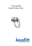
Keofitt Micro Port
Contents:
Contents: ......................................................................................................................................1
Introduction............................................................................................................................2
Presentation: ................................................................................................................................2
Type 900017, 900056 and 900057. ........................................................................................3
Mounting instructions ..................................................................................................................4
Guideline welding values:......................................................................................................5
Block diagram for welding to pipe and tank................................................................................6
Keofitt Micro Port type P, pipe (900057)...............................................................................6
Keofitt Micro Port T, tank (900056): ....................................................................................6
Keofitt Micro Port type P, pipe (900017)...............................................................................6
Everyday use of the Micro Port: ..................................................................................................7
Sterilisation: ...........................................................................................................................7
Sampling: ...............................................................................................................................7
Disassembly and assembly: .........................................................................................................8
Order of operation to replace membrane................................................................................8
Accessories: .................................................................................................................................8
Accessories: .................................................................................................................................9
Alternative: ..................................................................................................................................9
Micro Port manual 14/01/2004
1
Introduction
Manufacturer:
Keofitt a/s,
Hans Egedes Vej 19
5210 Odense NV
Denmark
Micro Port, Type:
900017 Micro Port Type P with 12x1 pipe connection.
900056 Micro Port Type T for tank connection.
900057 Micro Port Type P for pipe connection.
Presentation:
The Micro Ports are designed for samples taken with Hypodermic needle or syringe with minimum
risk of contamination. This is acquired by thick %XW\O,,5membrane and overall design with the
purpose of eliminating all dead spaces and crevasses where bacteria could cultivate.
The Keofitt Micro port is hygienic, easy to use and maintain, way of getting samples via
hypodermic needle or syringe in a safe way.
The Micro Port is available in 3 versions. First (900056) has a flat seat for tank welding. There are 2
versions for Pipe welding one (900017) has an integrated 12x1 pipe connection for easy installation
in a system. The second (900057) is for welding on pipes of larger dimensions and has a connection
profile that accommodates the thinner pipe-wall thus providing maximum welding quality.
Warning!
The system is designed for use in working conditions of 0-6 bar (g). Please note that
the sealing capacity is reduced with increased frequency of piercing.
Micro Port manual 14/01/2004
2
Type 900017, 900056 and 900057.
900017
900056
Part list
Nr. Part Nr.
1
9001XX*
2
900824
3
900049
4
900155
5
900840
Part name
Micro port Base
O-Ring 14 x 4
Membrane %XW\O,,5 Hex nut m.p.
Pivot screw micro port
900057
Qty
1
1
1
1
1
Nr.
6
7
8
9
Part Nr.
990055
900822
900441
900077
Part name
Wick for micro port
O-Ring 9,3 x 2,4
Plug m.p.
St. st. Chain for micro port
*were XX stands for the last 2 Letters in the complete port ordering no.
Where to use 900017:
Mounted by welding on pipes DN10
Where to use 900056:
Mounted by welding on any tank
Where to use 900057:
Mounted by welding on any pipe min Ø25
Material:
316L (1,4404)
Membrane: %XW\O,,5
Material certificate:
3.1.B
Optional dimension:
NW25
Inner surface:
Ra 0,8 my
How to use :
Manually operated.
Pressure range:
0-6 bar(g)
Temp. Range:
1-110ْC
Electro polish outside standard
Micro Port manual 14/01/2004
3
Qty
1
1
1
1
Mounting instructions
Location: It does not matter if the Micro Port is installed vertical or horizontal, it only matters
that the Micro Port is in contact with the product and has good access for sampling.
Before welding: Remember to disassemble the micro port base and hex nut.
The micro port and the hex nut must be separated during welding. Rubber plugs,
chain and membrane must be removed from the base, as heat from the welding
process will otherwise damage them.
Welding instructions: See sketch on next page.
Micro Port for welding is available in two types: T (tank) and P (pipe).
1.
For type T (tank) it is necessary to drill a hole ø28 mm into the tank wall. Then fit the Micro
Port into this hole, flush with the inside of the tank. Welding should be carried out as a
penetration welding.
Material thickness less than 4 mm:
Weld from inside.
Material thickness greater than 4 mm:
Weld from both in- and outside.
Since type T has a solid end piece, the valve will not be damaged by penetration welding.
However, the use of purge gas in either the form of Argon or Formier gas is recommended in
order to give the best result.
Important! When grinding/polishing the internal weld, the Micro Port seat area must not be
damaged.
2.
For type P (pipe) penetration welding must be carried out from outside.
Micro port is machined with a recess-like shoulder on the outside of the end piece which gives
approximately the same material thickness (1.5mm material thickness) as in the pipe wall.
This machined shoulder can be modified according to the customer’s wishes.
Micro Port manual 14/01/2004
4
The welding result will be best if the following method is used:
A collar is made on the pipe section so that the Micro Port has a flat contact face. This flaring
must look like a T-piece, as shown in the example below.
•
The pipe section and the base are sealed with sponge rubber or similar.
•
Purge gas such as Argon or Formier gas is fed through the valve body into the pipe
section and the system is now filled with 6 times the estimated volume of the pipe
section. All O2 is thus expelled from the system and welding can commence.
•
Welding can take place with the purge gas continually flowing in the system.
•
The gas remains in the system until the item is hand warm, after which the set-up can be
dismantled.
Guideline welding values:
Micro Port welded onto a 2 mm 3” stainless steel:
Micro Port welded onto a 1.25 mm 2” stainless steel:
40-50 Amps.
approx. 30 Amp.
It should be noted that Keofitt can supply all P type Micro Port welded onto a pipe section
according to customer specifications. Flaring is thus avoided and only an orbital (girth) weld is
required.
Micro Port manual 14/01/2004
5
Block diagram for welding to pipe and tank
Keofitt Micro Port type P, pipe (900057).
Welded to pipe
Keofitt Micro Port T, tank (900056):
Welded to Tank
Outside
Welded to Tank
inside
Keofitt Micro Port type P, pipe (900017).
Welded to Pipe, with
Orbital welding
Micro Port manual 14/01/2004
6
Everyday use of the Micro Port:
Use wick for sterilisation Keofitt item number 900055.
Sterilisation:
1.
2.
3.
4.
5.
Remove cap.
Soak cotton wick in disinfectant / alcohol.
Put the soaked wick in the cap.
Rub the inside of the Micro Port with the soaked wick.
Close the cap with wick in place.
Sampling:
1.
2.
3.
4.
5.
Remove the cap from the Micro Port.
Sterilize the Micro Port.
Pierce the membrane with Hypodermic needle / syringe.
Extract Sample.
Sterilize the Micro Port and put cap in place with wick.
Warning! With increased number of samples taken with each membrane the danger of cross
contamination increases and the membranes ability to sustain pressure decreases.
Maintenance:
Micro Port manual 14/01/2004
The membrane along with the cotton wick should be replaced with
every production batch.
7
Disassembly and assembly:
Order of operation to replace membrane
1.
2.
3.
4.
5.
6.
7.
8.
9.
Remove cap and cotton wick.
Turn hex nut counter clockwise and pull out of the base.
Pull out old membrane.
Put new membrane in place and press until it is firmly in place.
Take sanitary precautions, for example run disinfectant soaked cotton wick
over the membrane or autoclave it.
Put Hex nut in base and turn clockwise until the Micro port is completely
assembled.
Put new disinfectant soaked cotton wick in cap.
Sterilize inside of Micro Port with the cotton wick.
Put cap in place along with the cotton wick.
Micro Port manual 14/01/2004
8
Accessories:
Item
Hypodermic needle 40mm piercing
Cotton wick for sterilization
Membrane
Type
Short
Normal
Butyl IIR
Item-no
900054
900055
900049
900055 Cotton wick
for sterilization
900049 (10,5mm)
Butyl IIR
900054 Hypodermic
needle 40mm piercing
Alternative:
Keofitt Multi Micro Port 49™ (item no. 840 000) is designed to take many samples in every
production period. It eliminates the danger of cross contamination between samples via the
membrane. It also eliminates the risk of introducing old product from previous sample into the
process. Since fewer samples are taken from each membrane the pressure resistance also remains
more stable and higher.
Micro Port manual 14/01/2004
9